EP1132249B1 - Vehicle for traveling on uneven ground - Google Patents
Vehicle for traveling on uneven ground Download PDFInfo
- Publication number
- EP1132249B1 EP1132249B1 EP01105896A EP01105896A EP1132249B1 EP 1132249 B1 EP1132249 B1 EP 1132249B1 EP 01105896 A EP01105896 A EP 01105896A EP 01105896 A EP01105896 A EP 01105896A EP 1132249 B1 EP1132249 B1 EP 1132249B1
- Authority
- EP
- European Patent Office
- Prior art keywords
- clutch
- shaft
- oil
- torque converter
- transmission
- Prior art date
- Legal status (The legal status is an assumption and is not a legal conclusion. Google has not performed a legal analysis and makes no representation as to the accuracy of the status listed.)
- Expired - Lifetime
Links
- 230000005540 biological transmission Effects 0.000 claims description 54
- 230000003321 amplification Effects 0.000 claims description 2
- 238000003199 nucleic acid amplification method Methods 0.000 claims description 2
- 239000003921 oil Substances 0.000 description 42
- 239000002828 fuel tank Substances 0.000 description 4
- 239000010687 lubricating oil Substances 0.000 description 4
- 230000007935 neutral effect Effects 0.000 description 4
- 239000010720 hydraulic oil Substances 0.000 description 3
- 238000010586 diagram Methods 0.000 description 2
- 230000001603 reducing effect Effects 0.000 description 2
- 230000035939 shock Effects 0.000 description 2
- 238000006243 chemical reaction Methods 0.000 description 1
- 230000008878 coupling Effects 0.000 description 1
- 238000010168 coupling process Methods 0.000 description 1
- 238000005859 coupling reaction Methods 0.000 description 1
- 230000006866 deterioration Effects 0.000 description 1
- 230000001050 lubricating effect Effects 0.000 description 1
- 239000004576 sand Substances 0.000 description 1
- 239000007858 starting material Substances 0.000 description 1
- 239000000725 suspension Substances 0.000 description 1
- 238000010408 sweeping Methods 0.000 description 1
Images

Classifications
-
- B—PERFORMING OPERATIONS; TRANSPORTING
- B60—VEHICLES IN GENERAL
- B60K—ARRANGEMENT OR MOUNTING OF PROPULSION UNITS OR OF TRANSMISSIONS IN VEHICLES; ARRANGEMENT OR MOUNTING OF PLURAL DIVERSE PRIME-MOVERS IN VEHICLES; AUXILIARY DRIVES FOR VEHICLES; INSTRUMENTATION OR DASHBOARDS FOR VEHICLES; ARRANGEMENTS IN CONNECTION WITH COOLING, AIR INTAKE, GAS EXHAUST OR FUEL SUPPLY OF PROPULSION UNITS IN VEHICLES
- B60K17/00—Arrangement or mounting of transmissions in vehicles
- B60K17/02—Arrangement or mounting of transmissions in vehicles characterised by arrangement, location, or kind of clutch
-
- F—MECHANICAL ENGINEERING; LIGHTING; HEATING; WEAPONS; BLASTING
- F16—ENGINEERING ELEMENTS AND UNITS; GENERAL MEASURES FOR PRODUCING AND MAINTAINING EFFECTIVE FUNCTIONING OF MACHINES OR INSTALLATIONS; THERMAL INSULATION IN GENERAL
- F16H—GEARING
- F16H2200/00—Transmissions for multiple ratios
- F16H2200/003—Transmissions for multiple ratios characterised by the number of forward speeds
- F16H2200/0043—Transmissions for multiple ratios characterised by the number of forward speeds the gear ratios comprising four forward speeds
-
- Y—GENERAL TAGGING OF NEW TECHNOLOGICAL DEVELOPMENTS; GENERAL TAGGING OF CROSS-SECTIONAL TECHNOLOGIES SPANNING OVER SEVERAL SECTIONS OF THE IPC; TECHNICAL SUBJECTS COVERED BY FORMER USPC CROSS-REFERENCE ART COLLECTIONS [XRACs] AND DIGESTS
- Y10—TECHNICAL SUBJECTS COVERED BY FORMER USPC
- Y10S—TECHNICAL SUBJECTS COVERED BY FORMER USPC CROSS-REFERENCE ART COLLECTIONS [XRACs] AND DIGESTS
- Y10S180/00—Motor vehicles
- Y10S180/908—Motor vehicles with short wheelbase
Definitions
- the present invention relates to a vehicle for traveling on uneven ground, such as a saddle riding type four-wheel (three-wheel) buggy or the like.
- Ground contact pressure load per tire / ground contact area (ka/cm 2 ) is an important factor in traveling on a road surface having a small friction coefficient ( ⁇ ), such as a muddy, marshy, sandy, snowy, or graveled road surface.
- the ground contact pressure of a general passenger car is 1.8-2.3 kg/cm 2 so that traveling on a soft road having a small friction coefficient ( ⁇ ) in such a passenger car results in significant tire sinking as well as road surface grip deterioration in a road with small protrusions such as a graveled road, which degrades traveling performance.
- the ground contact pressure of the aforementioned low-pressure balloon tire is approx. 1/5th that of the passenger car - i.e. no more than 0.50 kg/cm 2 .
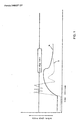
- Fig. 1 is a graph showing the relationship between torque transmission time (abscissas axis) and torque transmitted to a drive shaft (ordinate axis), of a vehicle for traveling on uneven ground fitted with the low-pressure balloon tires.
- a dotted line (b) shows the relationship for a conventional vehicle for traveling on uneven ground, equipped with a manual transmission (MT).
- US-A-5 636 608 discloses a vehicle in accordance with the preamble of claim 1. There, no torque converter is provided.
- the present invention provides a vehicle in accordance with claim 1.
- a torque converter in a power transmission path extends from a crank shaft of an engine to an input shaft of a multistage transmission in the vehicle for traveling on uneven ground, fitted with the low-pressure balloon tires.
- the ground contact pressure is assumed to be no more than 0,50 kg/cm 2 .
- the torque converter allows a smooth torque transmission. By overlapping the torque converter and the clutch when viewed in the longitudinal direction of the vehicle body, an effective us of space is ensured.
- the transmission torque (T) varies smoothly with the varying torque capacity ( ⁇ ) and rotation speed (N) so that it is difficult for the torque transmitted to the drive shaft to exceed the slip limit of the tire as shown by a solid line (a) in Fig. 1.
- the torque converter has a slip function, it performs slight torque transmission when power is input thereto from the engine. As a result, a creep phenomenon occurs, that is, the power is transmitted slightly to driving wheels even when the engine is in an idling state at the start when the multistage transmission is switched from a neutral to a low position. Also, the switching resistance of the multistage transmission is large because friction caused by the transmission torque acts continuously on a switching portion of the multistage transmission.
- the clutch provided in series with the torque converter is turned off to interrupt the power transmission to a downstream side of the clutch, irrespective of the presence of the torque converter, so that the creep phenomenon can be prevented even with the transmission in the low position during engine idling. Also, during the transmission operation, the clutch is first turned off to bring the transmission into a no-load state irrespective of the presence of the torque converter, so that the transmission can be lightly performed without an accompanying torque shock.
- slippage can be controlled by the torque converter provided in the power transmission path extending from the crank shaft, of the vehicle for traveling on uneven ground fitted with low-pressure balloon tires, to the input shaft of the multistage transmission, so that the traveling performance is improved while the possibility of breaking up a road surface or of damaging crops, etc. is reduced.
- the transmission torque depends on only a pressing force, and varies so significantly on account of the manual transmission (MT) that the torque transmitted to the propeller shaft exceeds the tire slip limit during traveling on a low friction coefficient ( ⁇ ) road, as shown by the dotted line (b) in Fig. 1.
- This invention is effective in a small ground contact pressure tire, that is, a tire that is less prone to sinking on a soft road and capable of tracking small irregularities of, for example, sand or gravel, particularly a low-pressure balloon tire having no more than 0.50 kg/cm 2 concrete ground contact pressure.
- the clutch in the power transmission path, besides the torque converter the clutch is provided to be in series therewith, so that the power being slightly transmitted from the engine to the propeller shaft, the so-called creep phenomenon, can be avoided in the neutral position.
- the clutch is provided to bring the transmission into a no-load state irrespective of the presence of the torque converter, so that the transmission can be lightly performed without accompanying torque shock.
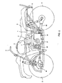
- the illustrated vehicle for traveling on uneven ground is a saddle riding type four-wheel buggy.
- the saddle riding type four-wheel buggy has a pair of left and right front wheels 2 for driving and steering suspended in a front portion of a body frame 1 made of a welded pipe, and a pair of left and right rear driving wheels 3 suspended in a rear portion thereof.
- the ground contact pressure of the front and rear wheels 2, 3 is no more than 0.50 kg/cm 2 , and in this embodiment low-pressure balloon tires having ground contact pressure of no more than 0.25 kg/cm 2 are used.
- a handle 4 for steering the front wheels 2 is provided on a front end of the body frame 1, while a fuel tank 5 is disposed in an intermediate portion between the front and the rear thereof.
- a straddle type seat 6 is disposed in an upper portion of the body frame 1 at the rear relative to the fuel tank 5.
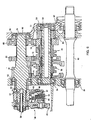
- a power unit P including an engine E, a torque converter T and a transmission mechanism M is fitted below the fuel tank 5 and the seat 6.
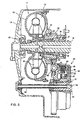
- One end of an exhaust pipe 8 is connected to a front exhaust port of a cylinder head 13 in an upper portion of a cylinder block 7 in the engine E, while the other end of the exhaust pipe 8 is connected through a side of the power unit P to a muffler 9 provided at the rear of the body.
- a cylinder block 7 is vertically provided in a crank case 10 of the engine E and a piston 12 is slidably fitted inside the cylinder block 7 via a sleeve 11, while an air cleaner (not shown) and a carburetor 14 are connected to a cylinder head 13 in an upper portion of the cylinder block 7.
- a crank shaft 16 is rotatably mounted in the crank case 10 via ball bearings 17, 17, and is coupled to the piston 12 by a connecting rod 18.
- crank shaft 16 is disposed in the longitudinal direction of the body so that a portion of the crank shaft 16 protruding forwardly (to the left in Fig. 4) from the crank case 10 is enclosed in an engine front cover 19 while its fore-end portion is rotatably mounted via a ball bearing 20, and a portion protruding backwardly (to the right in Fig. 4) from the crank case 10 is enclosed in an engine rear cover 21.
- a rotor 23 of an electric generator 22 is fitted to the crank shaft 16 facing into the engine rear cover 21, and a stator 24 disposed at an inner side of the rotor 23 is secured to the engine rear cover 21. Also, a recoil starter 25 with a knob protruding in a rear portion of the power unit P is fitted to the rear end of the crank shaft 16 to sandwich the electric generator 22 therebetween, and a start gear 15 that engages a starting motor is disposed between the electric generator 22 and the crank case 10.
- the torque converter T is also disposed in the front cover 19.
- the torque converter T comprises a pump impeller 30, a turbine runner 31 and a stator impeller 32, and is filled with oil so as to transmit power.
- This embodiment also has a temperature reducing effect on the torque converter T due to traveling wind sweeping across the engine E on a side thereof since the crank shaft 16 is disposed in the same longitudinal direction as that of the body, while the torque converter T is provided at the front end of the crank shaft 16.
- the pump impeller 30 rotates integrally with the crank shaft 16.
- the turbine runner 31 is disposed opposite the pump impeller 30 and is secured to a turbine shaft 34 arranged rotatably and coaxially relative to the crank shaft 16.
- the turbine shaft 34 is coupled to the pump impeller 30 by a one-way clutch 33. Also, the rotation of the pump impeller 30 is transmitted through the filling oil in the torque converter T to the turbine runner 31, while power is transmitted through a primary gear 35 and a clutch 40 to the transmission mechanism M.
- a stator shaft 36 of the stator impeller 32 is rotatable about a support member 38 fixed to the crank case 10 by means of a one-way clutch 37.
- a significant rotation difference between the pump impeller 30 and the turbine runner 31 causes no rotation of the stator impeller 32, so that a smooth flow of the oil from the turbine runner 31 permits torque amplification of torque reaction to the stator impeller 32.
- a small rotation difference between the pump impeller 30 and the turbine runner 31 allows the stator impeller 32 to idle so as to cause little resistance.
- the transmission mechanism M is held in a transmission case 50 formed integrally with the crank case 10.
- An input shaft 51 parallel to the crank shaft 16 is rotatably mounted to the transmission case 50 via a ball bearing 52, and likewise an output shaft 53 parallel to the crank shaft 16 is rotatably mounted to the transmission case 50 via a ball bearing 54.
- a clutch 40 is provided at one end of the input shaft 51 (at the front of the body). Effective use of space is ensured by arranging the clutch 40 between the torque converter T and the crank case 10 so that part of it overlaps the torque converter T when viewed in the longitudinal direction of the body.
- the clutch 40 includes a clutch center 41 being rotatable on the input shaft 51, a driven gear 43 being coupled to the clutch center 41 by a dampener spring 42 while being meshed with a driving gear 35 of the torque converter T, a plurality of first clutch plates 44 relatively unrotatably engaging the outer periphery of the clutch center 41, a plurality of second clutch plates 45 being superimposed and arranged between the first clutch plates 44, a clutch outer 46 containing the first and second clutch plates 44, 45 and rotating integrally with the input shaft 51 by relatively unrotatably engaging the outer periphery of the second clutch plates 45, and a hydraulic piston 47 being slidably fitted in the clutch outer 46.
- An oil chamber 48 is formed between the hydraulic piston 47 and the inside of the clutch outer 46, while a spring 49 is arranged on the opposite side of the oil chamber 48 for the hydraulic piston 47 to energize the hydraulic piston 47 in such a direction as to reduce the size of the oil chamber 48.
- the input shaft 51 is also axially formed with an oil path 56 communicating with the oil chamber 48 through an oil path 57 and being supplied with the oil through a pipe 58 extending to the engine front cover 19.
- the clutch 40 is turned on or off on the basis of a signal from an idling sensor and a transmission operation sensor. That is, during the engine idling and during the transmission operation, the clutch 40 is turned off so as not to transmit the power from the torque converter T to the input shaft 51. Accordingly, no creep phenomenon can occur during idling, and the resistance can be small during the transmission operation.
- the input shaft 51 is provided with driving gears 61, 62, 63 integral therewith or separate therefrom but which can rotate integrally the input shaft.
- the output shaft 53 is rotatably provided with driven gears 71, 72, 73, 74.
- the driving gear 61 is meshed with the driven gear 71, so that they constitute a first speed gear train
- the driving gear 62 is meshed with the driven gear 73, so that they constitute a second speed gear train
- the driving gear 63 is meshed with the driven gear 74, so that they constitute a third speed gear train.
- an intermediate gear provided for an intermediate shaft, not shown, existing between the input and output shafts 51, 53
- the driving gear 61 is meshed with the driven gear 72 so that they constitute a reverse gear train.
- the output shaft 53 is engaged with dog clutches 75, 76 rotatable integrally therewith and axially movable.
- the dog clutches 75, 76 are selectively engaged with any one of the driven gears 71, 73, 74, or 72, so that the first, the second, the third speed gear train, or the reverse gear train, is established.
- a neutral position is a state where the dog clutches 75, 76 are not engaged with any one of the driven gears 71, 73, 74, or 72.
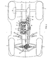
- a driving shaft 80 parallel to the output shaft 53 is rotatably mounted to the transmission case 50 by ball bearings 81, 82, while a driving gear 77 provided for the output shaft 53 is meshed with a driven gear 83 provided for the driving shaft 80, so that the driving shaft 80 is rotated at a gear ratio of the established gear train and in a rotation direction thereof, transmitting the rotation driving force through propeller shafts to front and rear wheels 2, 3.
- the driving force of the driving shaft 80 is transmitted to the front wheels 2 through the propeller shaft and a differential gear 84, while it is transmitted to the rear wheels 3 through the propeller shaft 86 held in a swing arm 85. Also, the driving shaft 80 is coupled to the propeller shaft by means of a constant velocity joint.
- a shaft 90 is provided parallel to an output shaft 53 in the transmission case 50, and is slidably provided with shift forks 91, 92.
- the dog clutches 75, 76 are separated from the shift forks 91, 92 in order to avoid intersecting of lines, but in reality the dog clutches 75 and 76 are engaged with the shift forks 91 and 92, respectively.
- the base ends of the shift forks 91, 92 are engaged with cam grooves 94, 95 of a shift drum 93 disposed parallel to the shaft 90 by transmitting the rotation of a shift spindle 96 through a fan-shaped gear 97 and a driven gear 98 to the shift drum 93.
- the shift spindle 96 is rotated by transmitting the rotation of an electric motor, not shown, through a speed reducing gear train. Also, a detector 99 for detecting a shift position is attached to the rear end of the shift drum 93 so as to determine the shift position from the rotation speed thereof.
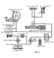
- Fig. 7 is an oil pressure control circuit diagram for the power unit P shown in Figs. 4, 5, 6.
- the oil is used as hydraulic oil for the torque converter T and the clutch 40, as well as lubricating oil for being fed to the crank shaft 16, the cylinder head 13, and the transmission mechanism M.
- the oil in the oil pan 100 is sucked through the oil strainer 101 by a feed pump 104, and is fed therefrom through an oil filter 105 to a linear solenoid valve 107.
- a linear solenoid valve 107 By operating the linear solenoid valve 107, the oil is fed into the oil chamber 48 of the clutch 40, and moves the hydraulic piston 47 to the right in Fig. 7.
- the hydraulic piston 47 presses the first and second clutch plates 44, 45 against each other, thereby turning on the clutch 40.
- the driving force is transmitted from the torque converter T to the transmission mechanism M by turning on the clutch 40.
- the turning off of the linear solenoid valve 107 reduces the oil pressure for feeding to the clutch 40, and therefore brings the clutch 40 into an off state.
- a clutch valve 108 is then operated so as to rapidly deliver the feed oil to the clutch 40 and thereby improve the operation response thereof.
- oil through the oil filter 105 is fed as lubricating oil to the cylinder head 13 and the transmission mechanism M, while the remaining oil is fed as hydraulic oil to the torque converter T, and is further fed from there to the crank shaft 16 as lubricating oil. Also, the oil used as lubricating or hydraulic oil is recycled into the oil pan 100.
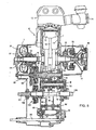
- Fig. 8 is a similar cross-sectional view to Fig. 4, illustrating another embodiment of the power unit P.
- a clutch 123 performing on/off operation in power transmission is interposed between a driving shaft 120 and a propeller shaft 121 for front wheels being rotatably mounted via a ball bearing 122 on the front cover 19 extending to the front of the transmission case 50, instead of coupling these shafts together by means of the constant velocity joint as in the aforementioned embodiment.
- the power is transmitted through the driving shaft 120 to the propeller shaft 121 for front wheels so that both the front and rear wheels are converted into driving wheels
- the power transmission to the propeller shaft 121 for front wheels is interrupted so that the front wheels function only as steering wheels.
- the invention suppresses slippage during traveling on uneven ground such as a muddy, marshy, sandy, snowy, or graveled road surface.
- cooler pump 103. oil cooler, 104. feed pump, 105. oil filter, 106. accumulator, 107. linear solenoid valve, 108. clutch valve, 109. shift valve, 110. shift solenoid valve, 120. driving shaft, 121. propeller shaft for front wheel, 122. ball bearing, 123. clutch, E. engine, M. transmission mechanism, P. power unit, T. torque converter.
Landscapes
- Engineering & Computer Science (AREA)
- Chemical & Material Sciences (AREA)
- Combustion & Propulsion (AREA)
- Transportation (AREA)
- Mechanical Engineering (AREA)
- Arrangement Of Transmissions (AREA)
- Arrangement And Driving Of Transmission Devices (AREA)
- Motor Power Transmission Devices (AREA)
- Automatic Cycles, And Cycles In General (AREA)
Applications Claiming Priority (2)
| Application Number | Priority Date | Filing Date | Title |
|---|---|---|---|
| JP2000065371 | 2000-03-09 | ||
| JP2000065371A JP4583541B2 (ja) | 2000-03-09 | 2000-03-09 | 車両 |
Publications (3)
| Publication Number | Publication Date |
|---|---|
| EP1132249A2 EP1132249A2 (en) | 2001-09-12 |
| EP1132249A3 EP1132249A3 (en) | 2003-06-25 |
| EP1132249B1 true EP1132249B1 (en) | 2005-11-16 |
Family
ID=18584911
Family Applications (1)
| Application Number | Title | Priority Date | Filing Date |
|---|---|---|---|
| EP01105896A Expired - Lifetime EP1132249B1 (en) | 2000-03-09 | 2001-03-09 | Vehicle for traveling on uneven ground |
Country Status (7)
| Country | Link |
|---|---|
| US (1) | US6712172B2 (enExample) |
| EP (1) | EP1132249B1 (enExample) |
| JP (1) | JP4583541B2 (enExample) |
| CN (1) | CN1329219C (enExample) |
| CA (1) | CA2340208C (enExample) |
| DE (1) | DE60114907T2 (enExample) |
| TW (1) | TW565514B (enExample) |
Families Citing this family (26)
| Publication number | Priority date | Publication date | Assignee | Title |
|---|---|---|---|---|
| JP2003120793A (ja) * | 2001-10-12 | 2003-04-23 | Honda Motor Co Ltd | 作動油等供給装置 |
| AU2003267815A1 (en) * | 2002-07-31 | 2004-02-23 | Honda Giken Kogyo Kabushiki Kaisha | Four-wheeled vehicle |
| DE10257571A1 (de) * | 2002-12-10 | 2004-06-24 | Adam Opel Ag | Vorrichtung und Verfahren zum Antrieb eines Kraftfahrzeuges mit einem Automatikgetriebe mit Drehmomentwandler und Anfahrkupplung |
| JP2005061590A (ja) * | 2003-08-20 | 2005-03-10 | Honda Motor Co Ltd | 車両用動力伝達装置 |
| JP2005155725A (ja) * | 2003-11-21 | 2005-06-16 | Yutaka Giken Co Ltd | 車両用動力伝達装置 |
| US7404568B1 (en) | 2004-03-08 | 2008-07-29 | Bombardier Recreational Products Inc. | Flip-down footrests for an all-terrain vehicle |
| US20060231322A1 (en) * | 2005-04-05 | 2006-10-19 | Bombardier Recreational Products Inc. | Vehicle with a Drive Shaft Passing Through an Engine |
| US7438153B2 (en) * | 2005-05-12 | 2008-10-21 | Artic Cat Inc. | All-terrain vehicle engine configuration |
| US20090038875A1 (en) * | 2005-05-12 | 2009-02-12 | Arctic Cat, Inc. | Off-road engine configuration with noise reduction system |
| JP4575256B2 (ja) * | 2005-08-31 | 2010-11-04 | 本田技研工業株式会社 | 四輪車両 |
| US7637343B2 (en) * | 2006-02-08 | 2009-12-29 | Yamaha Hatsudoki Kabushiki Kaisha | Small-sized vehicle |
| JP2008056109A (ja) * | 2006-08-31 | 2008-03-13 | Honda Motor Co Ltd | 鞍乗り型車両のエンジン配置構造 |
| JP4986684B2 (ja) * | 2007-03-30 | 2012-07-25 | 本田技研工業株式会社 | 鞍乗り型4輪車 |
| US7588010B2 (en) * | 2007-04-16 | 2009-09-15 | Yamaha Hatsudoki Kabushiki Kaisha | Power unit for a vehicle |
| US8256561B2 (en) * | 2007-04-16 | 2012-09-04 | Yamaha Hatsudoki Kabushiki Kaisha | Vehicle |
| US8596398B2 (en) | 2007-05-16 | 2013-12-03 | Polaris Industries Inc. | All terrain vehicle |
| USD595188S1 (en) | 2008-04-03 | 2009-06-30 | Polaris Industries Inc. | All terrain vehicle |
| US8075007B2 (en) * | 2007-05-16 | 2011-12-13 | Polaris Industries Inc. | Suspension for an all terrain vehicle |
| DE602008005077D1 (de) * | 2007-09-29 | 2011-04-07 | Honda Motor Co Ltd | Struktur zur Bereitstellung einer Kupplungssteuervorrichtung in einer Leistungseinheit für ein Motorrad |
| JP5005484B2 (ja) | 2007-09-29 | 2012-08-22 | 本田技研工業株式会社 | 鞍乗り型車両用パワーユニットにおけるクラッチ制御装置の配置構造 |
| CN101932470B (zh) | 2008-01-31 | 2013-07-17 | 庞巴迪动力产品公司 | 具有冷却通道的越野车 |
| US20090195035A1 (en) | 2008-02-04 | 2009-08-06 | Polaris Industries Inc. | ATV having arrangement for a passenger |
| CA2886639A1 (en) | 2012-09-28 | 2014-04-03 | Bombardier Recreational Products Inc. | Constant velocity joint with cooling ring |
| CN105346642B (zh) * | 2015-11-11 | 2017-10-31 | 管中林 | 车轮自动转换上下适应不平地面的越野四轮自行车 |
| US9738286B1 (en) * | 2016-06-14 | 2017-08-22 | Ford Global Technologies, Llc | Clutch for continuously variable transmission and method of operating clutch |
| CN109760500B (zh) * | 2019-03-14 | 2024-04-30 | 株洲齿轮有限责任公司 | 电动汽车、一体化动力总成及其外壳 |
Family Cites Families (26)
| Publication number | Priority date | Publication date | Assignee | Title |
|---|---|---|---|---|
| US3580350A (en) * | 1969-01-23 | 1971-05-25 | Gen Motors Corp | Vehicle power unit and drive train |
| JPS5812829A (ja) * | 1981-07-15 | 1983-01-25 | Nissan Motor Co Ltd | 四輪駆動車 |
| JPS58146756A (ja) * | 1982-02-23 | 1983-09-01 | Honda Motor Co Ltd | 車両用変速機 |
| JPH0784138B2 (ja) * | 1985-05-17 | 1995-09-13 | スズキ株式会社 | 鞍乗型車両の動力伝達装置 |
| AU613995B2 (en) * | 1987-12-11 | 1991-08-15 | Honda Giken Kogyo Kabushiki Kaisha | Drive system for automobile |
| JP2527895Y2 (ja) * | 1989-09-20 | 1997-03-05 | 三菱農機株式会社 | 農用トラクタ |
| JPH0446254U (enExample) * | 1990-08-27 | 1992-04-20 | ||
| KR960005976B1 (ko) * | 1991-07-31 | 1996-05-06 | 마쯔다 가부시기가이샤 | 자동차의 파우어트레인의 구조 |
| JP3004423B2 (ja) * | 1991-11-05 | 2000-01-31 | マツダ株式会社 | 車両のパワートレイン構造 |
| US5267488A (en) * | 1992-07-23 | 1993-12-07 | Hardeman Michael L | Drive train conversion apparatus |
| JP3221118B2 (ja) * | 1992-11-27 | 2001-10-22 | 株式会社エクォス・リサーチ | ハイブリット車輌における動力伝達装置 |
| JPH07195949A (ja) * | 1993-12-29 | 1995-08-01 | Honda Motor Co Ltd | 鞍乗型車両用パワーユニット |
| US5636608A (en) * | 1994-07-13 | 1997-06-10 | Honda Giken Kogyo Kabushiki Kaisha | Power unit for a vehicle |
| JPH0885352A (ja) * | 1994-09-20 | 1996-04-02 | Suzuki Motor Corp | 鞍状型四輪車の動力伝達機構 |
| JPH08239999A (ja) * | 1995-03-03 | 1996-09-17 | Mitsubishi Corp | 生コンクリートの床面を走行駆動する方法及び走行駆動車 |
| JP3880681B2 (ja) * | 1997-03-14 | 2007-02-14 | 富士重工業株式会社 | 無段式自動変速装置 |
| JPH10291420A (ja) * | 1997-04-22 | 1998-11-04 | Yamaha Motor Co Ltd | エンジンの動力伝達装置 |
| US6170597B1 (en) * | 1997-04-30 | 2001-01-09 | Yamaha Hatsudoki Kabushiki Kaisha | Transmission for offroad vehicle |
| JP3781518B2 (ja) * | 1997-08-12 | 2006-05-31 | 富士重工業株式会社 | 自動変速装置 |
| US5951434A (en) * | 1998-08-31 | 1999-09-14 | Richards; Victor | Planetary gear transmission for a light vehicle such as a motorcycle |
| JP4216932B2 (ja) * | 1998-11-05 | 2009-01-28 | 富士重工業株式会社 | 車両用駆動装置 |
| EP1001187B1 (en) | 1998-11-13 | 2004-01-07 | Yutaka Giken Co., Ltd. | Transmission system for small-size vehicle |
| JP4326091B2 (ja) * | 1998-11-13 | 2009-09-02 | 株式会社ユタカ技研 | 小型車両用伝動装置 |
| JP2000233786A (ja) * | 1999-02-17 | 2000-08-29 | Yamaha Motor Co Ltd | 車両における左右車輪への駆動力伝達構造 |
| US6386067B1 (en) * | 1999-11-11 | 2002-05-14 | Yutaka Giken Co., Ltd. | Transmitting system for small-sized vehicle |
| JP4163356B2 (ja) | 1999-12-22 | 2008-10-08 | 本田技研工業株式会社 | 不整地走行用鞍乗型車両 |
-
2000
- 2000-03-09 JP JP2000065371A patent/JP4583541B2/ja not_active Expired - Fee Related
-
2001
- 2001-03-02 TW TW090104850A patent/TW565514B/zh not_active IP Right Cessation
- 2001-03-09 DE DE60114907T patent/DE60114907T2/de not_active Expired - Lifetime
- 2001-03-09 CA CA002340208A patent/CA2340208C/en not_active Expired - Fee Related
- 2001-03-09 EP EP01105896A patent/EP1132249B1/en not_active Expired - Lifetime
- 2001-03-09 CN CNB011178558A patent/CN1329219C/zh not_active Expired - Fee Related
- 2001-03-09 US US09/801,641 patent/US6712172B2/en not_active Expired - Fee Related
Also Published As
| Publication number | Publication date |
|---|---|
| EP1132249A3 (en) | 2003-06-25 |
| US20010023788A1 (en) | 2001-09-27 |
| DE60114907D1 (de) | 2005-12-22 |
| US6712172B2 (en) | 2004-03-30 |
| JP2001253380A (ja) | 2001-09-18 |
| DE60114907T2 (de) | 2006-05-24 |
| CA2340208A1 (en) | 2001-09-09 |
| CN1329219C (zh) | 2007-08-01 |
| CN1320528A (zh) | 2001-11-07 |
| CA2340208C (en) | 2008-07-29 |
| TW565514B (en) | 2003-12-11 |
| EP1132249A2 (en) | 2001-09-12 |
| JP4583541B2 (ja) | 2010-11-17 |
Similar Documents
| Publication | Publication Date | Title |
|---|---|---|
| EP1132249B1 (en) | Vehicle for traveling on uneven ground | |
| US4600074A (en) | All wheel drive vehicle | |
| CA2344730C (en) | Four wheeled vehicle for traveling on irregular road | |
| JP2000001127A (ja) | 四輪駆動車両 | |
| WO2014098893A1 (en) | Method and system for limiting belt slip in a continuously variable transmission | |
| US9541013B2 (en) | Method and system for limiting belt slip in a continuously variable transmission | |
| JP4553447B2 (ja) | 不整地走行用四輪車 | |
| JP4291927B2 (ja) | 車両の動力伝達装置 | |
| JPS60135327A (ja) | 4輪駆動車 | |
| US4735105A (en) | Transmission and drive arrangement for vehicle | |
| US20250172195A1 (en) | Reverse drive system for a motorized vehicle | |
| US6125961A (en) | Four-wheel drive vehicle | |
| JPS6127779A (ja) | 不整地走行用車両 | |
| JPH05221250A (ja) | リミッテッドスリップデフ装置 | |
| JPH1134676A (ja) | 作業車の走行駆動装置 | |
| JPH0571438B2 (enExample) | ||
| JPS624729Y2 (enExample) | ||
| JP3984700B2 (ja) | 四輪駆動車両 | |
| JP4769018B2 (ja) | 作業車 | |
| JPH0723298Y2 (ja) | 建設車両のアクスル | |
| JPS61169334A (ja) | 不整地走行用車輛 | |
| JPS63235762A (ja) | 無段変速機付車両の変速制御方法 | |
| JPH07164903A (ja) | 四輪駆動型作業車の走行用伝動構造 |
Legal Events
| Date | Code | Title | Description |
|---|---|---|---|
| PUAI | Public reference made under article 153(3) epc to a published international application that has entered the european phase |
Free format text: ORIGINAL CODE: 0009012 |
|
| AK | Designated contracting states |
Kind code of ref document: A2 Designated state(s): AT BE CH CY DE DK ES FI FR GB GR IE IT LI LU MC NL PT SE TR |
|
| AX | Request for extension of the european patent |
Free format text: AL;LT;LV;MK;RO;SI |
|
| PUAL | Search report despatched |
Free format text: ORIGINAL CODE: 0009013 |
|
| AK | Designated contracting states |
Designated state(s): AT BE CH CY DE DK ES FI FR GB GR IE IT LI LU MC NL PT SE TR |
|
| AX | Request for extension of the european patent |
Extension state: AL LT LV MK RO SI |
|
| 17P | Request for examination filed |
Effective date: 20030804 |
|
| AKX | Designation fees paid |
Designated state(s): DE FR GB SE |
|
| 17Q | First examination report despatched |
Effective date: 20040526 |
|
| GRAP | Despatch of communication of intention to grant a patent |
Free format text: ORIGINAL CODE: EPIDOSNIGR1 |
|
| GRAS | Grant fee paid |
Free format text: ORIGINAL CODE: EPIDOSNIGR3 |
|
| GRAA | (expected) grant |
Free format text: ORIGINAL CODE: 0009210 |
|
| AK | Designated contracting states |
Kind code of ref document: B1 Designated state(s): DE FR GB SE |
|
| REG | Reference to a national code |
Ref country code: GB Ref legal event code: FG4D |
|
| REF | Corresponds to: |
Ref document number: 60114907 Country of ref document: DE Date of ref document: 20051222 Kind code of ref document: P |
|
| REG | Reference to a national code |
Ref country code: SE Ref legal event code: TRGR |
|
| ET | Fr: translation filed | ||
| PLBE | No opposition filed within time limit |
Free format text: ORIGINAL CODE: 0009261 |
|
| STAA | Information on the status of an ep patent application or granted ep patent |
Free format text: STATUS: NO OPPOSITION FILED WITHIN TIME LIMIT |
|
| 26N | No opposition filed |
Effective date: 20060817 |
|
| PGFP | Annual fee paid to national office [announced via postgrant information from national office to epo] |
Ref country code: SE Payment date: 20110311 Year of fee payment: 11 |
|
| REG | Reference to a national code |
Ref country code: DE Ref legal event code: R084 Ref document number: 60114907 Country of ref document: DE |
|
| REG | Reference to a national code |
Ref country code: GB Ref legal event code: 746 Effective date: 20111128 |
|
| REG | Reference to a national code |
Ref country code: DE Ref legal event code: R084 Ref document number: 60114907 Country of ref document: DE Effective date: 20111128 |
|
| REG | Reference to a national code |
Ref country code: SE Ref legal event code: EUG |
|
| PG25 | Lapsed in a contracting state [announced via postgrant information from national office to epo] |
Ref country code: SE Free format text: LAPSE BECAUSE OF NON-PAYMENT OF DUE FEES Effective date: 20120310 |
|
| PGFP | Annual fee paid to national office [announced via postgrant information from national office to epo] |
Ref country code: FR Payment date: 20140311 Year of fee payment: 14 |
|
| PGFP | Annual fee paid to national office [announced via postgrant information from national office to epo] |
Ref country code: DE Payment date: 20150305 Year of fee payment: 15 |
|
| PGFP | Annual fee paid to national office [announced via postgrant information from national office to epo] |
Ref country code: GB Payment date: 20150304 Year of fee payment: 15 |
|
| REG | Reference to a national code |
Ref country code: FR Ref legal event code: ST Effective date: 20151130 |
|
| PG25 | Lapsed in a contracting state [announced via postgrant information from national office to epo] |
Ref country code: FR Free format text: LAPSE BECAUSE OF NON-PAYMENT OF DUE FEES Effective date: 20150331 |
|
| REG | Reference to a national code |
Ref country code: DE Ref legal event code: R119 Ref document number: 60114907 Country of ref document: DE |
|
| GBPC | Gb: european patent ceased through non-payment of renewal fee |
Effective date: 20160309 |
|
| PG25 | Lapsed in a contracting state [announced via postgrant information from national office to epo] |
Ref country code: GB Free format text: LAPSE BECAUSE OF NON-PAYMENT OF DUE FEES Effective date: 20160309 Ref country code: DE Free format text: LAPSE BECAUSE OF NON-PAYMENT OF DUE FEES Effective date: 20161001 |