EP1130331B1 - Verfahren und Vorrichtung zur Belüftung und Temperierung eines Raumes - Google Patents
Verfahren und Vorrichtung zur Belüftung und Temperierung eines Raumes Download PDFInfo
- Publication number
- EP1130331B1 EP1130331B1 EP01103817A EP01103817A EP1130331B1 EP 1130331 B1 EP1130331 B1 EP 1130331B1 EP 01103817 A EP01103817 A EP 01103817A EP 01103817 A EP01103817 A EP 01103817A EP 1130331 B1 EP1130331 B1 EP 1130331B1
- Authority
- EP
- European Patent Office
- Prior art keywords
- primary air
- air
- room
- pressure chamber
- primary
- Prior art date
- Legal status (The legal status is an assumption and is not a legal conclusion. Google has not performed a legal analysis and makes no representation as to the accuracy of the status listed.)
- Expired - Lifetime
Links
Images


Classifications
-
- F—MECHANICAL ENGINEERING; LIGHTING; HEATING; WEAPONS; BLASTING
- F24—HEATING; RANGES; VENTILATING
- F24F—AIR-CONDITIONING; AIR-HUMIDIFICATION; VENTILATION; USE OF AIR CURRENTS FOR SCREENING
- F24F1/00—Room units for air-conditioning, e.g. separate or self-contained units or units receiving primary air from a central station
- F24F1/01—Room units for air-conditioning, e.g. separate or self-contained units or units receiving primary air from a central station in which secondary air is induced by injector action of the primary air
-
- F—MECHANICAL ENGINEERING; LIGHTING; HEATING; WEAPONS; BLASTING
- F24—HEATING; RANGES; VENTILATING
- F24F—AIR-CONDITIONING; AIR-HUMIDIFICATION; VENTILATION; USE OF AIR CURRENTS FOR SCREENING
- F24F1/00—Room units for air-conditioning, e.g. separate or self-contained units or units receiving primary air from a central station
- F24F1/0007—Indoor units, e.g. fan coil units
- F24F1/0071—Indoor units, e.g. fan coil units with means for purifying supplied air
-
- F—MECHANICAL ENGINEERING; LIGHTING; HEATING; WEAPONS; BLASTING
- F24—HEATING; RANGES; VENTILATING
- F24F—AIR-CONDITIONING; AIR-HUMIDIFICATION; VENTILATION; USE OF AIR CURRENTS FOR SCREENING
- F24F13/00—Details common to, or for air-conditioning, air-humidification, ventilation or use of air currents for screening
- F24F13/26—Arrangements for air-circulation by means of induction, e.g. by fluid coupling or thermal effect
-
- Y—GENERAL TAGGING OF NEW TECHNOLOGICAL DEVELOPMENTS; GENERAL TAGGING OF CROSS-SECTIONAL TECHNOLOGIES SPANNING OVER SEVERAL SECTIONS OF THE IPC; TECHNICAL SUBJECTS COVERED BY FORMER USPC CROSS-REFERENCE ART COLLECTIONS [XRACs] AND DIGESTS
- Y02—TECHNOLOGIES OR APPLICATIONS FOR MITIGATION OR ADAPTATION AGAINST CLIMATE CHANGE
- Y02B—CLIMATE CHANGE MITIGATION TECHNOLOGIES RELATED TO BUILDINGS, e.g. HOUSING, HOUSE APPLIANCES OR RELATED END-USER APPLICATIONS
- Y02B30/00—Energy efficient heating, ventilation or air conditioning [HVAC]
- Y02B30/56—Heat recovery units
Definitions
- the invention relates to a method for ventilation and temperature control of a room, in which primary air supplied to a device and secondary air in the device from the primary air induced from the room and mixed with the primary air and then supplied to the room the space in addition to the primary air mixed with the secondary air under a different blow-out direction and / or from a different location of the device pure primary air is also supplied.
- a method is e.g. in GB 2 144 212 A disclosed.
- the relevant Device of blown primary air induces a secondary air flow, which then is tempered as mixed air from primary air and secondary air in a heat exchanger. Subsequently the tempered mixed air flow is emitted at the top of the device.
- the separate delivery of pure primary air is also on the top the device possible.
- the known procedure has the disadvantage that the mixed air volume flow to be led through the heat exchanger is very large, which is why a large volume heat exchanger is required, which causes correspondingly high costs. Furthermore, a large one is used for circulating the large mixed air volume flow Fan power required, which in turn adversely affects the energy consumption of the device effect.
- the induction devices for performing the known method are usually in the Set up near a wall or parapet of a room and give the supply air essentially vertically upwards into the room, whereas the one of the heat exchanger Air supplied to the device mostly horizontally out of the room into the device flows.
- the living area of people is particularly in the office, where such ventilation methods are used, usually at a distance of approx. 1 up to 1.5 m away from the device inside the room.
- a disadvantage of the known method is that, for example, in summer, if the supply air to the room is cooled, only in the area where people stay there is an insufficient cooling effect.
- the highly inductive individual rays are namely blown vertically or obliquely upwards into the room, causing the facade or the inner sun protection can be cooled. Further inside the room in the people's lounge area there is therefore less cooling to dissipate the body heat of the person or Computer waste heat available.
- the Secondary air drawn in from the room is heated with the help of a heat exchanger, which in Thermal shielding in conjunction with the vertically upward blowing jets the facade is done.
- the room flow is essentially determined by the thermals of the supply air jets influenced, i.e. due to the exit pulse of the individual beams upwards and the higher temperature of the total supply air compared to the indoor air goes to the facade parallel rays on the ceiling into a horizontal flow.
- the air flow runs from the ceiling to the corridor wall. This leads to a in the usual lounge area in front of the parapet, users in the backflow zone located so that it has a supply air that is already strongly mixed with room air reduced quality.
- the invention has for its object a method for ventilation and temperature control propose a room with which the air quality, especially in the lounge area by people who are typically at a greater or lesser distance from the location of the supply air located, can be improved noticeably.
- a device is also proposed with which the method according to the invention can be carried out in a simple manner leaves.
- the lounge area is not only in the invention Reverse flow area of an induced indoor air roll, but can be via the pure primary air supply supplied with high quality air that is ongoing from a hygienic point of view become.
- the secondary air volume flow to be led through the heat exchanger is considerably smaller than the mixed air volume flow consisting of secondary air and primary air.
- the latter will tempered in the process known from GB 2 144 212 A overall, which is why the Heat exchanger must be much larger and therefore more expensive.
- two separate supply air flows can be generated, one - preferably depending on the outside air temperature - the temperature the primary air has a temperature of approx. 16 to 20 ° C and the second one for the room depending on the control of a heat exchanger can be individually controlled in temperature.
- the work area Pure primary air is supplied in the form of directional jets, which makes it possible a variable jet alignment with individual flow requirements Fresh air can be met.
- the primary air mixed with secondary air near a vertically or horizontally oriented boundary surface of the Space is supplied substantially parallel to this boundary surface.
- the effect of the facade shielding can be used both in cooling and in heating can be achieved particularly effectively.
- a further development of the method is that the pure primary air essentially at an angle of 45 ° to the vertical and from a boundary surface of the room is fed away directed.
- the typical stay area can be from Provide people in a room with the primary air particularly well, which makes them particularly special great comfort for the room user.
- a device for ventilation and temperature control of a room with which the invention has a primary air inlet through which the device Primary air can be supplied, with the help of directed primary air secondary air is inducible and can be sucked in from the room through at least one secondary air inlet and, mixed with primary air, can be returned to the room through at least one supply air outlet is and wherein the device has a heat exchanger and the space by at least a primary air outlet pure primary air can be supplied.
- the heat exchanger viewed in the direction of flow of the secondary air, arranged in front of a mixing shaft, in which the tempered secondary air can be mixed with primary air.
- An embodiment of the device according to the invention is by a first pressure chamber characterized in which the primary air inlet opens and from the nozzles for induction of Secondary air and a primary air duct leading to a second pressure chamber, the second pressure chamber being provided with at least one primary air outlet.
- a primary air outlet contains a rotatable disc element, which has a plurality of outlet channels running at an angle to its axis of rotation, through which the pure primary air can flow.
- the first one can Pressure chamber can be divided into two rooms, which have at least one closable opening can be connected to one another, the primary air inlet and the primary air duct having communicate with the first room and the nozzles for induction of secondary air the second room can be acted upon.
- the transition period when only one there is little need for heating or cooling capacity, or in the absence of room users, i.e. at times when there is no heat from people, computers or lighting energy can be saved by switching off the primary air nozzles become.
- This mode of operation also ensures basic ventilation receive the advantage of an optimal fresh air supply at the workplace.
- a particularly advantageous embodiment of the device according to the invention consists in that the first pressure chamber forms a lower part of the cuboid device and a vertical aligned mixing shaft, facing a parapet, is arranged above it, whereby primary air flows vertically from below into the mixing shaft and secondary air horizontally towards the parapet, one next to the mixing shaft and Flows above the first pressure chamber arranged heat exchanger and then in the Mixing shaft flows in and the secondary air mixed with primary air via a ventilation grille can be delivered to the room, one running next to the heat exchanger Primary air duct to the second pressure chamber arranged above the heat exchanger leads, which is flush with the ventilation grille of the mixing shaft and with one A plurality of distributed in the longitudinal direction of the second pressure chamber and the device Primary air outlets is provided.
- an upper part having the ventilation grille of the mixing shaft and that with a section of the primary air duct and the or Second pressure chamber provided with primary air connections form a common outlet element, which is removable from the device.
- the mixed with primary air Secondary air near the parapet can be discharged vertically upwards from the device pure primary air further towards the interior of the room, directed away from the parapet, at an angle Able to horizontally emitted from the device and room air as secondary air horizontally on the parapet can be sucked into the device.
- This can meet the requirements after effective facade shielding in summer and winter as well as optimal Fresh air supply at the workplace is best met.
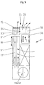
- 1 to 3 show a device for ventilation and temperature control, designated overall by 1 of a room with a bottom 2 of a housing 3 on a not closer illustrated floor of the room and with a rear wall 4 of the housing 3 on a likewise Parapet of the room, not shown, is set up below a window.
- the device 1 is provided with a primary air inlet 5 through which the device 1 is connected a primary air supply system, not shown, can be connected.
- primary air it is outside air that depends on using a central processing plant prepared from the respective outside temperature and with a temperature of approx. 16 up to 20 ° C is provided.
- this will only be necessary in rare cases.
- the primary air inlet 5 opens into a first pressure chamber 6, which extends over the entire Base of the housing 3 extends.
- a cover plate 7 of the pressure chamber 6 is with a A plurality of nozzles 8 are provided, which overflow the supplied under slight excess pressure Primary air from the pressure chamber 6 in a arranged above and vertically allow mixing shaft 9 extending above.
- the mixing shaft 9 is on the one hand limited by the rear wall 4 and on the other hand by a heat exchanger 10, which is next to the mixing shaft 9 and is - like the latter - almost over the entire length the device 1 extends.
- the heat exchanger 10 is via connections 11 with a heat transfer fluid loadable, whereby a separate heating and cooling register is available is. Alternatively, two separate coils are possible in a lamella package.
- the secondary air mixed with primary air passes through a ventilation grille 15, which forms an upper end of the mixing shaft 9 or the housing 3, according to arrows 16, substantially in the vertical direction slightly from the parapet directed away from the device into the room to be ventilated and tempered.
- a primary air duct 17 extends from the upper cover plate 7 of the pressure chamber 6 2 at the right end of the device 1 and vertically after is led above.
- the primary air duct 17 opens into a horizontally oriented second Pressure chamber 18, which extends essentially over the entire length of the device 1 and with its top flush with the top of the grille 15 for the Primary air mixed secondary air.
- the second pressure chamber 18 is an outlet area the mixing shaft 9 upstream on the side facing away from the parapet.
- In the top 19 of the second pressure chamber 18 are spaced apart five primary air outlets 20 arranged by the pure primary air to the room under different Exit directions can be given.
- the primary air outlets 20 each have in a horizontal plane rotatable disc element 21, each with seven in relation on its axis of rotation at an angle of approximately 30 ° to the horizontal Outlet channels 22 is provided.
- the direction of discharge of the primary air from the device 1 can be changed (see arrows 23), the alignment is always slightly inclined upwards.
- the device 1 'shown in FIG. 4 differs from the device 1 according to FIGS Fig. 1 to 3 through a modified primary air inlet 5 ', facing away from the parapet Part 25 of the first pressure chamber 6 'opens. From this part 25 of the pressure chamber 6 ' the primary air duct 17 also extends vertically upwards.
- Part 25 of the pressure chamber 6 ' is closed in the direction of the parapet part 26 of the Pressure chamber 6 ', which is provided on its upper side with the nozzles 8.
- An overflow cross section 27 between the two parts 25 and 26 of the pressure chamber 6 'is by means of a Motor-adjustable flap 28 can be released or closed.
- the primary air emerging from the nozzles 8 essentially has the task of secondary air to induce via the heat exchanger 10 to thereby heat or cool them can.
- Heating or cooling capacity required so that the heat exchanger can be used without support the primary air emerging through the nozzles 8 can be operated. It works in this Operation like a conventional convector, i.e. in the case of heating, air flows according to Arrows 29 and 30 from right to left through the heat exchanger 10 and then vertically upwards from the ventilation grille 15.
- the air flows in the cooling case according to the Arrows 31 and 32 from above through the ventilation grille 15 into the device 1 'in order to do this directed away from the parapet after passing through the heat exchanger 10 again.
- a free convection through the heat exchanger 10 is made possible by the fact that the flap 28 is brought into the closed position, whereby the nozzle flow is prevented.
- the direct one Fresh air supply to the workplaces via the adjustable primary air outlets 20 remains in this case, however, since the connection between the primary air inlet 5 ' and the primary air outlets 20 is always present.
Landscapes
- Engineering & Computer Science (AREA)
- Chemical & Material Sciences (AREA)
- Combustion & Propulsion (AREA)
- Mechanical Engineering (AREA)
- General Engineering & Computer Science (AREA)
- Ventilation (AREA)
- Central Air Conditioning (AREA)
Description
- Fig. 1
- einen Querschnitt durch eine erste Ausführungsform;
- Fig. 2
- einen Längsschnitt durch die Ausführungsform gemäß Fig. 1;
- Fig. 3
- eine Draufsicht auf die Ausführungsform gemäß Fig. 1;
- Fig. 4
- einen Querschnitt durch eine alternative Ausführungsform und
- Fig. 5
- einen Querschnitt durch eine wiederum andere Ausführungsform.
Claims (12)
- Verfahren zur Belüftung und Temperierung eines Raumes, bei dem einer Vorrichtung Primärluft zugeführt und in der Vorrichtung von der Primärluft Sekundärluft aus dem Rauminneren induziert und mit der Primärluft vermischt und sodann dem Raum zugeführt wird, wobei dem Raum zusätzlich zu der mit der Sekundärluft gemischten Primärluft unter einer anderen Ausblasrichtung und/oder von einer anderen Stelle der Vorrichtung aus auch reine Primärluft zugeführt wird, dadurch gekennzeichnet, dass die induzierte Sekundärluft vor der Mischung mit der Primärluft temperiert wird.
- Verfahren nach Anspruch 1, dadurch gekennzeichnet, dass die reine Primärluft in Form von gerichteten Strahlen zugeführt wird.
- Verfahren nach Anspruch 1 oder 2, dadurch gekennzeichnet, dass die mit Sekundärluft gemischte Primärluft in der Nähe einer vertikal oder horizontal ausgerichteten Begrenzungsfläche des Raumes im wesentlichen parallel zu dieser Begrenzungsfläche zugeführt wird.
- Verfahren nach einem der Ansprüche 1 bis 3, dadurch gekennzeichnet, dass die reine Primärluft im wesentlichen unter einem Winkel von 45° zur Vertikalen und von einer Begrenzungsfläche des Raumes weg zugeführt wird.
- Vorrichtung (1, 1', 1") zur Belüftung und Temperierung eines Raumes, mit einem Primärlufteinlass (5), über den der Vorrichtung (1, 1', 1") Primärluft zuführbar ist, wobei mit Hilfe von gerichtet strömender Primärluft Sekundärluft induzierbar ist, die durch mindestens einen Sekundärlufteinlaß (12) aus dem Raum ansaugbar und, mit Primärluft gemischt, durch mindestens einen Zuluftauslass (15) wieder an den Raum abgebbar ist, und wobei die Vorrichtung einen Wärmetauscher (10) aufweist und dem Raum durch mindestens einen Primärluftauslass (20) reine Primärluft zuführbar ist, dadurch gekennzeichnet, dass der Wärmetauscher (10) in Strömungsrichtung der Sekundärluft betrachtet vor einem Mischungsschacht (9) angeordnet ist, in dem die temperierte Sekundärluft mit Primärluft mischbar ist.
- Vorrichtung nach Anspruch 5, gekennzeichnet durch eine Druckkammer (6), in die der Primärlufteinlass (5) mündet und von der Düsen (8) zur Induktion von Sekundärluft sowie ein zu einer zweiten Druckkammer (18) führender Primärluftkanal (17) ausgehen,
wobei die zweite Druckkammer (18) mit mindestens einem Primärluftauslass (20) versehen ist. - Vorrichtung nach Anspruch 5 oder 6, dadurch gekennzeichnet, dass die Austrittsrichtung der reinen Primärluft veränderbar ist.
- Vorrichtung nach Anspruch 7, dadurch gekennzeichnet, dass ein Primärluftauslass (20) ein drehbares Scheibenelement (21) enthält, das mehrere unter einem Winkel zu seiner Drehachse verlaufende Austrittskanäle (22) aufweist, die von der reinen Primärluft durchströmbar sind.
- Vorrichtung nach einem der Ansprüche 6 bis 8, dadurch gekennzeichnet, dass die erste Druckkammer (5) in zwei Räume (25, 26) unterteilt ist, die über mindestens eine verschließbare Öffnung miteinander verbindbar sind, wobei der Primärlufteinlass (5') und der Primärluftkanal (17) mit dem ersten Raum (25) in Verbindung stehen und die Düsen (8) zur Induktion von Sekundärluft über den zweiten Raum (26) beaufschlagbar sind.
- Vorrichtung nach einem der Ansprüche 5 bis 9, dadurch gekennzeichnet, dass die erste Druckkammer (6, 6') ein Unterteil der quaderförmigen Vorrichtung (1, 1', 1") bildet und ein vertikal ausgerichteter Mischungsschacht (9, 9'), einer Brüstung zugewandt, darüber angeordnet ist, wobei Primärluft vertikal von unten in den Mischungsschacht (9, 9') einströmt und Sekundärluft, horizontal auf die Brüstung zu gerichtet, zunächst einen neben dem Mischungsschacht (9, 9') und oberhalb der ersten Druckkammer (6, 6') angeordneten Wärmetauscher (10) durchströmt und dann in den Mischungsschacht (9, 9') einströmt und die mit Primärluft gemischte Sekundärluft über ein Lüftungsgitter an den Raum abgebbar ist und wobei ein neben dem Wärmetauscher (10) verlaufender Primärluftkanal (17, 17') zu der oberhalb des Wärmetauschers (10) angeordneten zweiten Druckkammer (18) führt, die bündig mit dem Lüftungsgitter (15) des Mischungsschachts (9, 9') abschließt und mit einer Mehrzahl von in Längsrichtung der zweiten Druckkammer (18) und der Vorrichtung (1, 1', 1") verteilt angeordneten Primärluftauslässen (20) versehen ist.
- Vorrichtung nach Anspruch 9, dadurch gekennzeichnet, dass ein die Lüftungsgitter (15) aufweisendes Oberteil (33) des Mischungsschachts (9') und die mit einem Abschnitt des Primärluftkanals (17') versehene zweite Druckkammer (18) ein gemeinsames Auslaßelement (35) bilden, das als Ganzes von der Vorrichtung (1") entfernbar ist.
- Vorrichtung nach einem der Ansprüche 5 bis 11, dadurch gekennzeichnet, dass die mit Primärluft gemischte Sekundärluft brüstungsnah zumindest nach oben aus der Vorrichtung (1, 1', 1") abgebbar ist, die reine Primärluft weiter zum Rauminneren hin, von der Brüstung weg gerichtet, nach oben bis horizontal jeweils an die Vorrichtung (1") abgebbar und Raumluft als Sekundärluft horizontal auf die Brüstung zu in die Vorrichtung (1") einsaugbar ist.
Applications Claiming Priority (2)
| Application Number | Priority Date | Filing Date | Title |
|---|---|---|---|
| DE10010119A DE10010119A1 (de) | 2000-03-03 | 2000-03-03 | Verfahren und Vorrichtung zur Belüftung und Temperierung eines Raumes |
| DE10010119 | 2000-03-03 |
Publications (3)
| Publication Number | Publication Date |
|---|---|
| EP1130331A2 EP1130331A2 (de) | 2001-09-05 |
| EP1130331A3 EP1130331A3 (de) | 2002-05-08 |
| EP1130331B1 true EP1130331B1 (de) | 2004-05-12 |
Family
ID=7633204
Family Applications (1)
| Application Number | Title | Priority Date | Filing Date |
|---|---|---|---|
| EP01103817A Expired - Lifetime EP1130331B1 (de) | 2000-03-03 | 2001-02-16 | Verfahren und Vorrichtung zur Belüftung und Temperierung eines Raumes |
Country Status (5)
| Country | Link |
|---|---|
| EP (1) | EP1130331B1 (de) |
| AT (1) | ATE266842T1 (de) |
| CZ (1) | CZ2001697A3 (de) |
| DE (2) | DE10010119A1 (de) |
| PL (1) | PL346209A1 (de) |
Cited By (2)
| Publication number | Priority date | Publication date | Assignee | Title |
|---|---|---|---|---|
| US8469783B2 (en) | 2006-01-16 | 2013-06-25 | Halton Oy | Supply air terminal device and method for regulating the airflow rate |
| DE102012203573A1 (de) | 2012-03-07 | 2013-09-12 | Yit Germany Gmbh | Vorrichtung zur Heizung und/oder Kühlung eines Raums |
Families Citing this family (15)
| Publication number | Priority date | Publication date | Assignee | Title |
|---|---|---|---|---|
| DE102004034210B4 (de) * | 2004-07-14 | 2006-04-20 | M+W Zander Gebäudetechnik GmbH | Verfahren und Vorrichtung zur Belüftung und Temperierung |
| WO2006011251A1 (ja) * | 2004-07-30 | 2006-02-02 | Mitsubishi Heavy Industries, Ltd. | 冷却庫及び空気冷媒式冷却システム |
| WO2006011297A1 (ja) | 2004-07-30 | 2006-02-02 | Mitsubishi Heavy Industries, Ltd. | 空気冷媒式冷却装置 |
| US20070051126A1 (en) | 2004-11-29 | 2007-03-08 | Seiichi Okuda | Air refrigerant type freezing and heating apparatus |
| DE102007007711B4 (de) * | 2007-02-16 | 2014-03-27 | Ltg Ag | Verfahren und Vorrichtung zum Lüften, Heizen und/oder Kühlen eines Raumes |
| DE102007014274A1 (de) * | 2007-03-16 | 2008-09-25 | Ltg Aktiengesellschaft | Verfahren zum Temperieren von Luft in einem Raum sowie Wandelement zur Raumtemperierung |
| FI122285B (fi) * | 2007-03-30 | 2011-11-15 | Halton Oy | Tulo- ja poistoilmalaite |
| FI122965B (fi) * | 2009-12-09 | 2012-09-14 | Halton Oy | Tuloilmalaite ja menetelmä ilmanvaihdossa |
| DE102011014393A1 (de) * | 2011-03-11 | 2012-09-13 | Ltg Aktiengesellschaft | Verfahren zum Belüften, Heizen und/oder Kühlen eines Raumes sowie entsprechende Vorrichtung |
| DE102011114335A1 (de) * | 2011-09-21 | 2013-03-21 | Ltg Aktiengesellschaft | Als Induktionsgerät ausgebildetes lufttechnisches Gerät sowie Verfahren zum Betreiben des Geräts |
| DE102011114334A1 (de) * | 2011-09-21 | 2013-03-21 | Ltg Aktiengesellschaft | Lufttechnisches Gerät |
| DE102013109702A1 (de) | 2013-09-05 | 2015-03-05 | Caverion Deutschland GmbH | Luftauslass sowie Verfahren zu dessen Umrüstung |
| DE102019104872A1 (de) * | 2019-02-26 | 2020-08-27 | Kampmann Gmbh | Klimatisierung von Räumen mit Quellluftzuführung und Temperierung |
| US11421897B2 (en) | 2019-03-29 | 2022-08-23 | Air Distribution Technologies Ip, Llc | Air diffuser for localized climate control |
| CN110940084A (zh) * | 2019-12-20 | 2020-03-31 | 珠海格力电器股份有限公司 | 喷射器、冷梁末端、冷梁系统 |
Family Cites Families (8)
| Publication number | Priority date | Publication date | Assignee | Title |
|---|---|---|---|---|
| US2032692A (en) * | 1935-03-23 | 1936-03-03 | B F Sturtevant Company Inc | Heat exchange unit |
| US3946647A (en) * | 1973-05-07 | 1976-03-30 | Aktiebolaget Svenska Flaktfabriken | Device for preferably cooling a room by a ventilation air stream |
| CH570588A5 (de) * | 1973-06-19 | 1975-12-15 | Luwa Ag | |
| CH569935A5 (de) * | 1973-10-08 | 1975-11-28 | Luwa Ag | |
| CH654901A5 (en) * | 1981-09-30 | 1986-03-14 | Sulzer Ag | Device for conditioning the air inside a room |
| DE3719134A1 (de) * | 1987-06-06 | 1988-12-15 | T O P Consulting Ingenieurgese | Luftaustrittsvorrichtung |
| DE4017272A1 (de) * | 1989-08-25 | 1991-03-07 | Scheu & Wirth Ag | Luftaufbereitungsgeraet fuer einzelraeume mit dezentraler zumischung von aussenluft |
| DE19826566C2 (de) * | 1998-06-15 | 2003-05-15 | Ltg Holding Gmbh | Verfahren und Vorrichtung zum Belüften eines Raumes |
-
2000
- 2000-03-03 DE DE10010119A patent/DE10010119A1/de not_active Withdrawn
-
2001
- 2001-02-16 DE DE50102230T patent/DE50102230D1/de not_active Expired - Lifetime
- 2001-02-16 EP EP01103817A patent/EP1130331B1/de not_active Expired - Lifetime
- 2001-02-16 AT AT01103817T patent/ATE266842T1/de not_active IP Right Cessation
- 2001-02-23 CZ CZ2001697A patent/CZ2001697A3/cs unknown
- 2001-03-01 PL PL01346209A patent/PL346209A1/xx not_active Application Discontinuation
Cited By (3)
| Publication number | Priority date | Publication date | Assignee | Title |
|---|---|---|---|---|
| US8469783B2 (en) | 2006-01-16 | 2013-06-25 | Halton Oy | Supply air terminal device and method for regulating the airflow rate |
| DE102012203573A1 (de) | 2012-03-07 | 2013-09-12 | Yit Germany Gmbh | Vorrichtung zur Heizung und/oder Kühlung eines Raums |
| DE102012203573B4 (de) | 2012-03-07 | 2024-12-12 | Krantz Gmbh | Vorrichtung zur Heizung und/oder Kühlung eines Raums |
Also Published As
| Publication number | Publication date |
|---|---|
| EP1130331A2 (de) | 2001-09-05 |
| DE10010119A1 (de) | 2001-09-13 |
| CZ2001697A3 (cs) | 2001-10-17 |
| EP1130331A3 (de) | 2002-05-08 |
| DE50102230D1 (de) | 2004-06-17 |
| PL346209A1 (en) | 2001-09-10 |
| ATE266842T1 (de) | 2004-05-15 |
Similar Documents
| Publication | Publication Date | Title |
|---|---|---|
| EP1130331B1 (de) | Verfahren und Vorrichtung zur Belüftung und Temperierung eines Raumes | |
| DE69824602T2 (de) | Integrale luftauslassmodule und dazugehörige heiz- und kühlsysteme | |
| EP1918650B1 (de) | Verfahren zur Klimatisierung eines Raums und Klimatisierungsvorrichtung | |
| DE102010044590A1 (de) | Anordnung zur Belüftung eines Raums, insbesondere eines Laborraums | |
| EP4433752A1 (de) | Umluftmodul und umluftmodulsystem | |
| EP2846108B1 (de) | Deckenluftauslass | |
| DE69912031T2 (de) | Vorrichtung zum Belüften, Kühlen und/oder Beheizen eines Raumes | |
| EP1571402B1 (de) | Raumlufttechnische Einrichtung zum Heizen, Kühlen und/oder Belüften eines Raumes sowie entsprechendes Verfahren | |
| DE102007027839A1 (de) | Modulares Lüftungssystem | |
| DE19525945C2 (de) | Verfahren und Vorrichtung zur Erzeugung behaglicher Raumluftzustände | |
| DE3341827A1 (de) | Lueftungssystem fuer die raeume von gebaeuden | |
| EP1619447B1 (de) | Raumlüftungs- oder Raumklimagerät | |
| EP2161512B1 (de) | Dezentrales lufttechnisches Gerät sowie lufttechnische Anlage mit einem derartigen Gerät | |
| DE19758139C2 (de) | Verfahren und Vorrichtung zur Klimatisierung eines Raumes | |
| DE3242215A1 (de) | Injektor-raumklimageraet | |
| DE2922441C2 (de) | Induktionsgerät zur Belüftung von Aufenthaltsräumen | |
| DE2033195B2 (de) | Luftaustrittseinrichtung für Klimaanlagen | |
| DE9218498U1 (de) | Vorrichtung zum Bräunen des menschlichen Körpers | |
| CH654901A5 (en) | Device for conditioning the air inside a room | |
| EP2366959B1 (de) | Verfahren und Vorrichtung zum Lüften, Heizen und/oder Kühlen (Klimatisieren) von Gebäuden, insbesondere Räumen | |
| EP1256766B1 (de) | Lüftungssystem für die Räume von Gebäuden | |
| EP0807791B1 (de) | Lüftungssystem für die Räume von Gebäuden | |
| EP1027563B1 (de) | Wandelement zur klimatisierung von räumen | |
| DE2630504A1 (de) | Anordnung zur klimatisierung und belueftung von raeumen | |
| DE2714819A1 (de) | Lufttechnische anlage |
Legal Events
| Date | Code | Title | Description |
|---|---|---|---|
| PUAI | Public reference made under article 153(3) epc to a published international application that has entered the european phase |
Free format text: ORIGINAL CODE: 0009012 |
|
| AK | Designated contracting states |
Kind code of ref document: A2 Designated state(s): AT BE CH CY DE DK ES FI FR GB GR IE IT LI LU MC NL PT SE TR |
|
| AX | Request for extension of the european patent |
Free format text: AL;LT;LV;MK;RO;SI |
|
| RIN1 | Information on inventor provided before grant (corrected) |
Inventor name: SODEC, FRANC, DR.-ING. Inventor name: MAKULLA, DETLEF, DIPL.-ING. |
|
| PUAL | Search report despatched |
Free format text: ORIGINAL CODE: 0009013 |
|
| AK | Designated contracting states |
Kind code of ref document: A3 Designated state(s): AT BE CH CY DE DK ES FI FR GB GR IE IT LI LU MC NL PT SE TR |
|
| AX | Request for extension of the european patent |
Free format text: AL;LT;LV;MK;RO;SI |
|
| RIC1 | Information provided on ipc code assigned before grant |
Free format text: 7F 24F 1/00 A, 7F 24F 1/01 B, 7F 24F 13/26 B, 7F 24F 13/065 B |
|
| 17P | Request for examination filed |
Effective date: 20020627 |
|
| 17Q | First examination report despatched |
Effective date: 20020925 |
|
| AKX | Designation fees paid |
Designated state(s): AT BE CH CY DE DK ES FI FR GB GR IE IT LI LU MC NL PT SE TR |
|
| GRAP | Despatch of communication of intention to grant a patent |
Free format text: ORIGINAL CODE: EPIDOSNIGR1 |
|
| GRAS | Grant fee paid |
Free format text: ORIGINAL CODE: EPIDOSNIGR3 |
|
| GRAA | (expected) grant |
Free format text: ORIGINAL CODE: 0009210 |
|
| AK | Designated contracting states |
Kind code of ref document: B1 Designated state(s): AT BE CH CY DE DK ES FI FR GB GR IE IT LI LU MC NL PT SE TR |
|
| PG25 | Lapsed in a contracting state [announced via postgrant information from national office to epo] |
Ref country code: TR Free format text: LAPSE BECAUSE OF FAILURE TO SUBMIT A TRANSLATION OF THE DESCRIPTION OR TO PAY THE FEE WITHIN THE PRESCRIBED TIME-LIMIT Effective date: 20040512 Ref country code: IE Free format text: LAPSE BECAUSE OF FAILURE TO SUBMIT A TRANSLATION OF THE DESCRIPTION OR TO PAY THE FEE WITHIN THE PRESCRIBED TIME-LIMIT Effective date: 20040512 Ref country code: IT Free format text: LAPSE BECAUSE OF FAILURE TO SUBMIT A TRANSLATION OF THE DESCRIPTION OR TO PAY THE FEE WITHIN THE PRESCRIBED TIME-LIMIT;WARNING: LAPSES OF ITALIAN PATENTS WITH EFFECTIVE DATE BEFORE 2007 MAY HAVE OCCURRED AT ANY TIME BEFORE 2007. THE CORRECT EFFECTIVE DATE MAY BE DIFFERENT FROM THE ONE RECORDED. Effective date: 20040512 Ref country code: FR Free format text: LAPSE BECAUSE OF FAILURE TO SUBMIT A TRANSLATION OF THE DESCRIPTION OR TO PAY THE FEE WITHIN THE PRESCRIBED TIME-LIMIT Effective date: 20040512 Ref country code: FI Free format text: LAPSE BECAUSE OF FAILURE TO SUBMIT A TRANSLATION OF THE DESCRIPTION OR TO PAY THE FEE WITHIN THE PRESCRIBED TIME-LIMIT Effective date: 20040512 |
|
| REG | Reference to a national code |
Ref country code: GB Ref legal event code: FG4D Free format text: NOT ENGLISH |
|
| REG | Reference to a national code |
Ref country code: CH Ref legal event code: EP |
|
| REG | Reference to a national code |
Ref country code: IE Ref legal event code: FG4D Free format text: GERMAN |
|
| REF | Corresponds to: |
Ref document number: 50102230 Country of ref document: DE Date of ref document: 20040617 Kind code of ref document: P |
|
| PG25 | Lapsed in a contracting state [announced via postgrant information from national office to epo] |
Ref country code: GR Free format text: LAPSE BECAUSE OF FAILURE TO SUBMIT A TRANSLATION OF THE DESCRIPTION OR TO PAY THE FEE WITHIN THE PRESCRIBED TIME-LIMIT Effective date: 20040812 Ref country code: SE Free format text: LAPSE BECAUSE OF FAILURE TO SUBMIT A TRANSLATION OF THE DESCRIPTION OR TO PAY THE FEE WITHIN THE PRESCRIBED TIME-LIMIT Effective date: 20040812 Ref country code: DK Free format text: LAPSE BECAUSE OF FAILURE TO SUBMIT A TRANSLATION OF THE DESCRIPTION OR TO PAY THE FEE WITHIN THE PRESCRIBED TIME-LIMIT Effective date: 20040812 |
|
| PG25 | Lapsed in a contracting state [announced via postgrant information from national office to epo] |
Ref country code: ES Free format text: LAPSE BECAUSE OF FAILURE TO SUBMIT A TRANSLATION OF THE DESCRIPTION OR TO PAY THE FEE WITHIN THE PRESCRIBED TIME-LIMIT Effective date: 20040823 |
|
| REG | Reference to a national code |
Ref country code: CH Ref legal event code: NV Representative=s name: PA ALDO ROEMPLER |
|
| GBT | Gb: translation of ep patent filed (gb section 77(6)(a)/1977) |
Effective date: 20040824 |
|
| REG | Reference to a national code |
Ref country code: IE Ref legal event code: FD4D |
|
| PG25 | Lapsed in a contracting state [announced via postgrant information from national office to epo] |
Ref country code: LU Free format text: LAPSE BECAUSE OF NON-PAYMENT OF DUE FEES Effective date: 20050216 Ref country code: CY Free format text: LAPSE BECAUSE OF FAILURE TO SUBMIT A TRANSLATION OF THE DESCRIPTION OR TO PAY THE FEE WITHIN THE PRESCRIBED TIME-LIMIT Effective date: 20050216 |
|
| PGFP | Annual fee paid to national office [announced via postgrant information from national office to epo] |
Ref country code: GB Payment date: 20050216 Year of fee payment: 5 |
|
| PG25 | Lapsed in a contracting state [announced via postgrant information from national office to epo] |
Ref country code: MC Free format text: LAPSE BECAUSE OF NON-PAYMENT OF DUE FEES Effective date: 20050228 |
|
| PLBE | No opposition filed within time limit |
Free format text: ORIGINAL CODE: 0009261 |
|
| STAA | Information on the status of an ep patent application or granted ep patent |
Free format text: STATUS: NO OPPOSITION FILED WITHIN TIME LIMIT |
|
| 26N | No opposition filed |
Effective date: 20050215 |
|
| EN | Fr: translation not filed | ||
| PG25 | Lapsed in a contracting state [announced via postgrant information from national office to epo] |
Ref country code: GB Free format text: LAPSE BECAUSE OF NON-PAYMENT OF DUE FEES Effective date: 20060216 |
|
| GBPC | Gb: european patent ceased through non-payment of renewal fee |
Effective date: 20060216 |
|
| PGFP | Annual fee paid to national office [announced via postgrant information from national office to epo] |
Ref country code: AT Payment date: 20070213 Year of fee payment: 7 |
|
| PGFP | Annual fee paid to national office [announced via postgrant information from national office to epo] |
Ref country code: CH Payment date: 20070214 Year of fee payment: 7 |
|
| PG25 | Lapsed in a contracting state [announced via postgrant information from national office to epo] |
Ref country code: PT Free format text: LAPSE BECAUSE OF NON-PAYMENT OF DUE FEES Effective date: 20041012 |
|
| PGFP | Annual fee paid to national office [announced via postgrant information from national office to epo] |
Ref country code: BE Payment date: 20070423 Year of fee payment: 7 |
|
| PGFP | Annual fee paid to national office [announced via postgrant information from national office to epo] |
Ref country code: NL Payment date: 20080203 Year of fee payment: 8 |
|
| BERE | Be: lapsed |
Owner name: *KRANTZ-TKT G.M.B.H. Effective date: 20080228 |
|
| REG | Reference to a national code |
Ref country code: CH Ref legal event code: PCAR Free format text: ALDO ROEMPLER PATENTANWALT;BRENDENWEG 11 POSTFACH 154;9424 RHEINECK (CH) |
|
| REG | Reference to a national code |
Ref country code: CH Ref legal event code: PL |
|
| PG25 | Lapsed in a contracting state [announced via postgrant information from national office to epo] |
Ref country code: CH Free format text: LAPSE BECAUSE OF NON-PAYMENT OF DUE FEES Effective date: 20080229 Ref country code: LI Free format text: LAPSE BECAUSE OF NON-PAYMENT OF DUE FEES Effective date: 20080229 |
|
| PG25 | Lapsed in a contracting state [announced via postgrant information from national office to epo] |
Ref country code: AT Free format text: LAPSE BECAUSE OF NON-PAYMENT OF DUE FEES Effective date: 20080216 |
|
| PG25 | Lapsed in a contracting state [announced via postgrant information from national office to epo] |
Ref country code: BE Free format text: LAPSE BECAUSE OF NON-PAYMENT OF DUE FEES Effective date: 20080228 |
|
| NLV4 | Nl: lapsed or anulled due to non-payment of the annual fee |
Effective date: 20090901 |
|
| PG25 | Lapsed in a contracting state [announced via postgrant information from national office to epo] |
Ref country code: NL Free format text: LAPSE BECAUSE OF NON-PAYMENT OF DUE FEES Effective date: 20090901 |
|
| REG | Reference to a national code |
Ref country code: DE Ref legal event code: R081 Ref document number: 50102230 Country of ref document: DE Owner name: MAKULLA, DETLEF, DE Free format text: FORMER OWNER: CAVERION GMBH, 70499 STUTTGART, DE Effective date: 20110228 Ref country code: DE Ref legal event code: R081 Ref document number: 50102230 Country of ref document: DE Owner name: CAVERION DEUTSCHLAND GMBH, DE Free format text: FORMER OWNER: CAVERION GMBH, 70499 STUTTGART, DE Effective date: 20110228 |
|
| REG | Reference to a national code |
Ref country code: DE Ref legal event code: R082 Ref document number: 50102230 Country of ref document: DE Representative=s name: BAUER WAGNER PRIESMEYER, PATENT- UND RECHTSANW, DE |
|
| REG | Reference to a national code |
Ref country code: DE Ref legal event code: R082 Ref document number: 50102230 Country of ref document: DE Representative=s name: BAUER WAGNER PRIESMEYER, PATENT- UND RECHTSANW, DE Effective date: 20140217 Ref country code: DE Ref legal event code: R081 Ref document number: 50102230 Country of ref document: DE Owner name: CAVERION DEUTSCHLAND GMBH, DE Free format text: FORMER OWNER: YIT GERMANY GMBH, 80992 MUENCHEN, DE Effective date: 20140217 Ref country code: DE Ref legal event code: R081 Ref document number: 50102230 Country of ref document: DE Owner name: MAKULLA, DETLEF, DE Free format text: FORMER OWNER: YIT GERMANY GMBH, 80992 MUENCHEN, DE Effective date: 20140217 Ref country code: DE Ref legal event code: R082 Ref document number: 50102230 Country of ref document: DE Representative=s name: PATENT- & RECHTSANWAELTE BAUER WAGNER PRIESMEY, DE Effective date: 20140217 |
|
| PGFP | Annual fee paid to national office [announced via postgrant information from national office to epo] |
Ref country code: DE Payment date: 20160229 Year of fee payment: 16 |
|
| REG | Reference to a national code |
Ref country code: DE Ref legal event code: R082 Ref document number: 50102230 Country of ref document: DE Ref country code: DE Ref legal event code: R081 Ref document number: 50102230 Country of ref document: DE Owner name: MAKULLA, DETLEF, DE Free format text: FORMER OWNER: CAVERION DEUTSCHLAND GMBH, 80992 MUENCHEN, DE |
|
| REG | Reference to a national code |
Ref country code: DE Ref legal event code: R084 Ref document number: 50102230 Country of ref document: DE |
|
| REG | Reference to a national code |
Ref country code: DE Ref legal event code: R119 Ref document number: 50102230 Country of ref document: DE |
|
| PG25 | Lapsed in a contracting state [announced via postgrant information from national office to epo] |
Ref country code: DE Free format text: LAPSE BECAUSE OF NON-PAYMENT OF DUE FEES Effective date: 20170901 |