EP1127987B1 - Spülvorrichtung für Toiletten - Google Patents
Spülvorrichtung für Toiletten Download PDFInfo
- Publication number
- EP1127987B1 EP1127987B1 EP01104831A EP01104831A EP1127987B1 EP 1127987 B1 EP1127987 B1 EP 1127987B1 EP 01104831 A EP01104831 A EP 01104831A EP 01104831 A EP01104831 A EP 01104831A EP 1127987 B1 EP1127987 B1 EP 1127987B1
- Authority
- EP
- European Patent Office
- Prior art keywords
- flushing device
- flushing
- cylinder
- valves
- operating system
- Prior art date
- Legal status (The legal status is an assumption and is not a legal conclusion. Google has not performed a legal analysis and makes no representation as to the accuracy of the status listed.)
- Expired - Lifetime
Links
Images


Classifications
-
- E—FIXED CONSTRUCTIONS
- E03—WATER SUPPLY; SEWERAGE
- E03D—WATER-CLOSETS OR URINALS WITH FLUSHING DEVICES; FLUSHING VALVES THEREFOR
- E03D5/00—Special constructions of flushing devices, e.g. closed flushing system
- E03D5/02—Special constructions of flushing devices, e.g. closed flushing system operated mechanically or hydraulically (or pneumatically) also details such as push buttons, levers and pull-card therefor
- E03D5/024—Operated hydraulically or pneumatically
-
- E—FIXED CONSTRUCTIONS
- E03—WATER SUPPLY; SEWERAGE
- E03D—WATER-CLOSETS OR URINALS WITH FLUSHING DEVICES; FLUSHING VALVES THEREFOR
- E03D1/00—Water flushing devices with cisterns ; Setting up a range of flushing devices or water-closets; Combinations of several flushing devices
- E03D1/02—High-level flushing systems
- E03D1/14—Cisterns discharging variable quantities of water also cisterns with bell siphons in combination with flushing valves
- E03D1/142—Cisterns discharging variable quantities of water also cisterns with bell siphons in combination with flushing valves in cisterns with flushing valves
-
- E—FIXED CONSTRUCTIONS
- E03—WATER SUPPLY; SEWERAGE
- E03D—WATER-CLOSETS OR URINALS WITH FLUSHING DEVICES; FLUSHING VALVES THEREFOR
- E03D5/00—Special constructions of flushing devices, e.g. closed flushing system
- E03D5/10—Special constructions of flushing devices, e.g. closed flushing system operated electrically, e.g. by a photo-cell; also combined with devices for opening or closing shutters in the bowl outlet and/or with devices for raising/or lowering seat and cover and/or for swiveling the bowl
- E03D5/105—Special constructions of flushing devices, e.g. closed flushing system operated electrically, e.g. by a photo-cell; also combined with devices for opening or closing shutters in the bowl outlet and/or with devices for raising/or lowering seat and cover and/or for swiveling the bowl touchless, e.g. using sensors
Definitions
- the invention relates to a flushing device for toilets according to the preamble of claim 1.
- toilet flushing systems The most common toilet flushing systems currently use a manual, mechanical actuation system. In recent years, however, more and more toilets with electrically assisted flushing device prevail, especially in public facilities such as hospitals, trains or restaurants. In these flushing systems, two groups are to be distinguished. In the first group, the flushing of the toilet by means of conventional lifting unit, which is operated electromechanically by means of solenoid lifters. Here are both manually operated electric or electropneumatic release systems and non-contact, automatic sensor systems are used.
- Object of the invention is in contrast, a flushing device for toilets of the type mentioned - to propose, in which the design effort is significantly reduced at the same time with the consumption of electrical energy.
- a flushing device for toilets characterized by the fact that a hydraulic actuation system is provided.
- the hydraulic actuation system is particularly characterized by high performance and low design effort, so that a particularly economical production is guaranteed.
- toilets are connected to the domestic water system, so that advantageously the water pressure or the hydraulic energy of the conduit system for the actuation of the flushing is to be used.
- This hydraulic actuation system hereby overcomes the water pressure which acts on the actuation system by means of water located in the reservoir.
- the actuation system comprises two bistable valves which require electrical energy only for an opening or closing pulse. This ensures that the electrical control of the actuation system and thus the entire flushing device according to the invention consumes very little electrical energy, so that corresponding batteries, accumulators, photovoltaic systems or the like can be dimensioned comparatively small and thus cost-effective.
- the actuating system comprises two cylinder-piston units. This makes a particularly simple actuation system feasible, so that a particularly cost-effective solution is realized.
- an air gap is provided between the valves and the cylinder-piston units, an inflow line being arranged in front of and an outflow line behind each air gap. This ensures on the one hand a hygienic decoupling of the pipe system with the reservoir.
- the air gaps of at least two supply lines intersect, it being possible for a discharge opening for filling the storage container to be actuated when the valves are opened simultaneously.
- This is in a simple way z. B. a two-volume flushing while constructive and functional combination of the water supply with the emptying or flushing guaranteed.
- This eliminates a corresponding mechanical water supply unit, d. h., That account for the previously commonly used valves with float unit.
- a considerable reduction of the effort and the cost of a flushing device according to the invention is ensured.
- the actuating system comprises an electrical control, so that, among other things, the comfort of modern toilets for the operator ensures is.
- the actuating system comprises a mains-independent, electrical power supply.
- a mains-independent, electrical power supply is realized by means of batteries, accumulators or photovoltaic systems.
- the grid-independent, electrical energy supply is realized by means of batteries, accumulators or photovoltaic systems.
- the actuation system comprises at least one non-contact sensor, so that the operation of the actuation system both takes place in a simple manner and meets maximum hygienic requirements, as they are to be ensured for example in food processing companies, hospitals or the like.
- At least one automatic control is provided, wherein the comfort for the user is additionally increased and corresponding standards are met.
- This can be used, for example, to comply with existing standards, which stipulate that the flushing is to be operated on both sides with hand or arm, without the user having to change the seating position.
- a Spülmengen Kunststoffung is provided so that either a large or small flush volume is released.
- an interval rinse or a special cleaning or disinfecting rinse can be implemented.
- a particular embodiment of the cylinder-piston unit comprises a ventilation opening and a discharge opening, so that, for example, a single-acting lifting cylinder is provided which is reset, for example due to gravity and / or a spring force.
- the venting or emptying opening is realized, for example, by means of a corresponding valve or by means of a defined leak of the cylinder-piston unit, the latter ensuring a further reduction in the constructional complexity of the flushing device according to the invention.
- the actuating system comprises two cylinder-piston units with different strokes, so that in a particularly simple manner, a two-quantity technique can be implemented. As a result, flushing with a small and a large flush volume is ensured in a simple manner.
- a corresponding actuating system is constructed by means of two functionally identical modules, for example using both two cylinder-piston units and two bistable valves, including appropriate controls, but only with an electronic unit.
- a coupling element for actuating conventional mechanical flushing systems is provided. This ensures that conventional flushing systems can be retrofitted with a flushing device according to the invention.
- the flushing device according to the invention builds in this embodiment on proven and inexpensive flushing systems, which in turn ensures a particularly economical production.
- a corresponding embodiment of the coupling element also ensures an actuation of conventional two-volume flushing systems, so that the flexible use of the flushing device according to the invention remains ensured.
- At least one manual control element is provided, so that a variety of other variants for controlling the flushing device are made possible.
- two additional manually operable proximity sensors ensure the selection between a small and a large flush volume, for example, a main sensor, in non-operation of the proximity sensors, ensures the safe triggering of the flushing.
- a remote release by disabled users can be realized.
- the remote release as well as the quantity selection for example by means of proximity sensors, also preferably takes place either by means of non-contact sensors or by means of electromechanical or mechanical elements.
- the operation of the flushing device is ensured, for example, by cleaning or maintenance personnel, so that inter alia a mechanical emergency release of the flushing without electronic control is made possible.
- At least one additional system can be controlled, so that, for example, a cleaning, disinfecting and / or fragrance agent is added to the rinsing medium.
- a cleaning, disinfecting and / or fragrance agent is added to the rinsing medium.
- a fan during and / or after using the toilet possibly fresh air in the - bring toilet space.
- a time-dependent control of at least one of the valves is provided. For example, this ensures that the flush only starts after leaving the user or that the filling of the reservoir takes place in dependence on the opening duration of the valves. It is also ensured that the valves are allowed to open only after a person lingered for an adjustable period of time before or on the toilet.
- the level sensor is realized, for example, as a level switch or water pressure sensor.
- FIG. 1 shows a toilet 2 with a flushing device 1 according to the invention.
- the flushing device 1 in this case comprises a reservoir 3, an actuating system 4 and for automatic, non-contact person detection, a main sensor 5 with a large sensor range.
- the flushing device 1 comprises two proximity sensors 6a, 6b by means of which a manual selection between a large and a small flushing amount is possible.
- the two proximity sensors 6a, 6b have a comparatively short range, wherein the main sensor 5 also ensures automatic purging insofar as the post-sensors 6a, 6b are not actuated. Only the two proximity sensors allow a needs-based flushing.
- the small flush volume allows a significant reduction in water consumption and thus contributes particularly to the protection of the environment.
- FIG. 1 shows a supply system 7 which, for example, is a conventional valve float system may include.
- a revision plate 8 ensures both easy maintenance of the flushing device and a simple arrangement of the main sensor 5 and the proximity sensors 6a, 6b.
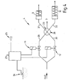
- FIG. 2 shows a more detailed embodiment of the actuation system 4.
- the actuation system 4 comprises a cylinder-piston unit 9 with a short stroke x and a cylinder-piston unit 10 with a long stroke y, so that the actuation system 4 comprises two comparable modules and due to the two different strokes can trigger two different flushing volumes.
- a bistable valve 11 or 12 is opened by means of electronic control, then a piston 13 or 14 is pressed in the z-direction so that a coupling element 15 is displaced in the z-direction by the distance x or y.
- a conventional flushing system 16 is thereby actuated and the toilet 2 flushed with a small or large flushing volume.
- the coupling element 15 can be additionally manually, mechanically operated.
- valves 11 and 12 are closed again, so that a spring 17 or 18, the piston 13 or 14 against the z-direction pushes back into the starting position.
- a ventilation 19 or 20 and a drain 21 and 22 ensure a corresponding function of the cylinder-piston unit 9 and 10.
- the emptying is 21 and 22 shown schematically in Figure 2 as a valve, which in the end position of Piston 13 or 14 is taken.
- the ventilation or emptying function can also by means of defined leaks the cylinder-piston unit 9 and 10 are ensured.
- FIG. 3 shows a block diagram of a non-inventive actuation system, including an electronic controller 23.
- the controller 23 is powered by means of a power supply 24, which may include, for example, a battery or a photovoltaic system, with electrical energy.
- the controller 23 includes an infrared sensor 25 and a manual override 26.
- This is both a non-contact basic function of Spülvor- - direction 1, for example by means of main sensor 5 and Nahsensoren 6a, 6b, as well as an additional manual operation ensures, for example, for disabled users the toilet at a suitable location, optionally on the backrest, the armrest or the like and for emergency or cleaning operations by maintenance or cleaning personnel.
- controller 23 allows driving an additional system 27, wherein, for example, a cleaning, disinfecting and / or fragrance agent can be added to the flushing medium if necessary.
- a fan can be controlled, which supplies the toilet room with fresh air.
- FIG. 4 shows a block diagram with a so-called aerial intersection 28, as provided according to the invention.
- two air paths intersect, which represent the extension of two supply lines 29 and 30, wherein on the opposite side of the two supply lines 29 and 30 each have a corresponding outflow line 31 and 32 is arranged.
- valve 11 If, for example, the valve 11 is opened, water flows via the inflow line 29 into the air-line intersection 28 and further via the outflow line 32 into the cylinder-piston unit 10 and actuates it, so that a large amount of purging is released. The same applies to the opening of the valve 12, wherein ultimately a purge is triggered with a small flush volume.
- a level switch 34 connected to the controller 23 causes, by means of the controller 23, closing of the valves 11 and 12, so that the filling of the storage container 3 is stopped and overflow is prevented.
Landscapes
- Engineering & Computer Science (AREA)
- Health & Medical Sciences (AREA)
- Life Sciences & Earth Sciences (AREA)
- Hydrology & Water Resources (AREA)
- Public Health (AREA)
- Water Supply & Treatment (AREA)
- Aviation & Aerospace Engineering (AREA)
- Mechanical Engineering (AREA)
- Sanitary Device For Flush Toilet (AREA)
- Detergent Compositions (AREA)
Description
- Die Erfindung betrifft eine Spülvorrichtung für Toiletten nach dem Oberbegriff des Anspruchs 1.
- Die derzeit gebräuchlichsten Spülvorrichtungen für Toiletten arbeiten mit einem manuellen, mechanischen Betätigungssystem. In den letzten Jahren setzen sich jedoch immer mehr Toiletten mit elektrisch unterstützter Spülvorrichtung durch, insbesondere in öffentlichen Einrichtungen wie Krankenhäusern, Zügen oder Gaststätten. Bei diesen Spülsystemen sind zwei Gruppen zu unterscheiden. Bei der ersten Gruppe erfolgt die Spülung der Toilette mittels herkömmlicher Hubeinheit, wobei diese elektromechanisch mittels Elektromagnetheber betätigt wird. Hierbei kommen sowohl manuell betätigte elektrische oder elektropneumatische Auslösesysteme als auch berührungslose, automatische Sensorsysteme zum Einsatz.
- Bei der zweiten Gruppe werden sogenannte Direkt-Hubsysteme eingesetzt, d. h., dass die herkömmlichen Hubeinheiten entfallen und lediglich elektromagnetische Hubsysteme den Spülvorgang auslösen. Hierbei kommen wiederum manuell betätigte elektrische oder elektro-pneumatische Auslösesysteme als auch berührungslose, automatische Sensorsysteme zum Einsatz.
- Diese herkömmlichen Spülvorrichtungen für Toiletten sind vergleichsweise aufwendig, verbrauchen teilweise sehr viel elektrische Energie, so dass ein netzunabhängiger Betrieb nicht zu realisieren ist. Zudem sind solche bekannten Systeme vergleichsweise kostenintensiv.
- Aus der EP 0 828 103 A1 ist eine Spülvorrichtung der eingangs genannten Art bekannt geworden, welche selbsthaltende Magnetventile zur Steuerung des Wasserstroms verwendet. Dadurch sind die erforderlichen elektrischen Ströme zur Betätigung gering und es genügt eine Batterie als Stromquelle. Diese bekannte Spülvorrichtung ist allerdings mit einem erheblichen konstruktiven Aufwand verbunden.
- Aufgabe der Erfindung ist es demgegenüber, eine Spülvorrichtung für Toiletten der eingangs genannten Art - vorzuschlagen, bei welcher der konstruktive Aufwand zugleich mit dem Verbrauch an elektrischer Energie deutlich reduziert ist.
- Diese Aufgabe wird ausgehend von einer Spülvorrichtung für Toiletten der einleitend genannten Art durch die kennzeichnenden Merkmale des Anspruchs 1 gelöst.
- Durch die in den Unteransprüchen genannten Maßnahmen sind vorteilhafte Ausführungen und Weiterbildungen der Erfindung möglich.
- Dem entsprechend zeichnet sich eine erfindungsgemäße Spülvorrichtung für Toiletten dadurch aus, dass ein hydraulisches Betätigungssystem vorgesehen ist.
- Das hydraulische Betätigungssystem zeichnet sich besonders durch eine hohe Leistung und einen geringen konstruktiven Aufwand auf, so dass eine besonders wirtschaftliche Fertigung gewährleistet ist. Im allgemeinen sind Toiletten an das häusliche Wassersystem angeschlossen, so dass in vorteilhafterweise der Wasserdruck bzw. die hydraulische Energie des Leitungssystems für die Betätigung der Spülung heranzuziehen ist. Dieses hydraulische Betätigungssystem überwindet hiermit den Wasserdruck, der mittels sich im Vorratsbehälter befindenden Wassers auf das Betätigungssystem einwirkt.
- Aus der Verwendung des Spülmediums zur Erzeugung einer Betätigungskraft resultiert eine besonders einfache konstruktive Ausführungsform der erfindungsgemäßen Spülvorrichtung.
- Dabei umfasst das Betätigungssystem zwei bistabile Ventile, die lediglich für einen Öffnungs- oder Schließimpuls elektrische Energie benötigen. Hierdurch wird gewährleistet, dass die elektrische Steuerung des Betätigungssystems und somit die gesamte erfindungsgemäße Spülvorrichtung sehr wenig elektrische Energie verbraucht, so dass entsprechende Batterien, Akkumulatoren, Fotovoltaik-Systeme oder dergleichen vergleichsweise klein zu dimensionieren und somit kostengünstig sind.
- Auch umfasst das Betätigungssystem zwei Zylinder-Kolben-Einheiten. Hiermit wird ein besonders einfaches Betätigungssystem realisierbar, so dass eine besonders kostengünstige Lösung realisiert wird.
- Zwischen den Ventilen und den Zylinder-Kolben-Einheiten ist erfindungsgemäß je eine Luftstrecke vorgesehen, wobei eine Zuflussleitung vor und eine Abflussleitung hinter jeder Luftstrecke angeordnet ist. Hiermit wird einerseits eine hygienische Entkopplung des Leitungssystems mit dem Vorratsbehälter gewährleistet.
- Luftstrecken zur hygienischen Entkoppelung, insbesondere zur Vermeidung eines möglichen Rückflusses aus dem Vorratsbehälter in das Trinkwasser-Leitungssystem sind an sich bekannt, z. B. aus der Norm DIN EN 1717:2000. Neu ist dagegen die erfindungsgemäße Erkenntnis, dass eine Luftstrecke, wie sie aus hygienischen Gründen für die Befüllung eines Vorratsbehälters erfoderlich sein kann, sich auch innerhalb eines Betätigungssystems zur Entleerung des Vorratsbehälters eignet.
- Das Vorsehen von zwei Luftstrecken ist beispielsweise dann vorteilhaft, wenn zur Toilettenspülung Regen- oder Brauchwasser verwendet werden soll und gleichzeitig ein Trinkwasseranschluß für die Spülvorrichtung vorgesehen - ist, der unter anderem bei Regen- oder Brauchwassermangel die ordnungsgemäße Funktion der Spülvorrichtung gewährleistet. Auch bei einer Zwei-Mengen-Spültechnik sind zwei Luftstrecken von Vorteil.
- Erfindungsgemäß kreuzen sich die Luftstrecken wenigstens zweier Zuflussleitungen, wobei bei einem gleichzeitigen Öffnen der Ventile eine Abflussöffnung zur Befüllung des Vorratsbehälters ansteuerbar ist. Hiermit wird in einfacher Weise z. B. eine Zwei-Mengen-Spültechnik bei gleichzeitiger konstruktiver sowie funktioneller Kombination der Wasserversorgung mit der Entleerung bzw. Spülung gewährleistet. Dadurch entfällt eine entsprechende mechanische Wasserversorgungseinheit, d. h., dass die im allgemeinen bisher gebräuchlichen Ventile mit Schwimmereinheit entfallen. Hierdurch ist eine erhebliche Reduktion des Aufwandes als auch der Kosten einer erfindungsgemäßen Spülvorrichtung gewährleistet.
- In einer Weiterbildung umfasst das Betätigungssystem eine elektrische Ansteuerung, so dass unter anderem der Komfort moderner Toiletten für den Bediener gewährleistet ist.
- Vorzugsweise umfasst das Betätigungssystem eine netzunabhängige, elektrische Energieversorgung. Hiermit ist ein besonders flexibler Einsatz erfindungsgemäßer Spülvorrichtungen gewährleistet. Beispielsweise wird die netzunabhängige, elektrische Energieversorgung mittels Batterien, Akkumulatoren oder Fotovoltaik-Systemen realisiert. Durch die Verwendung einer Niedervolt-Gleichspannung für die Energieversorgung wird unter anderem auch entsprechenden Sicherheitsvorschriften Rechnung getragen.
- Vorteilhafterweise umfasst das Betätigungssystem wenigstens einen berührungslosen Sensor, so dass die Bedienung des Betätigungssystems sowohl in einfacher Weise erfolgt als auch maximale hygienische Anforderungen erfüllt, wie sie beispielsweise in Lebensmittel verarbeitenden Betrieben, Krankenhäusern oder dergleichen zu gewährleisten sind.
- In einer besonderen Ausführungsform der Erfindung ist wenigstens eine automatische Steuerung vorgesehen, wobei der Komfort für den Benutzer zusätzlich erhöht wird und entsprechende Standards erfüllt werden. Hiermit können beispielsweise existierende Normvorschriften eingehalten werden, die festlegen, dass die Spülung beidseitig mit Hand oder Arm zu betätigen ist, ohne dass der Benutzer die Sitzposition verändern muss.
- Vorteilhafterweise ist eine Spülmengensteuerung vorgesehen, so dass wahlweise eine große oder kleine Spülmenge freigegeben wird. Vorzugsweise ist hierbei auch eine Intervallspülung oder eine spezielle Reinigungs- bzw. Desinfektionsspülung umsetzbar.
- Eine besondere Weiterbildung der Zylinder-Kolbeneinheit umfasst eine Belüftungsöffnung und eine Entleerungsöffnung, so dass beispielsweise ein einfach wirkender Hubzylinder vorzusehen ist, der beispielsweise aufgrund der Schwerkraft und/oder einer Federkraft zurückgestellt wird. Hierbei wird die Belüftungs- oder Entleerungsöffnung beispielsweise mittels eines entsprechenden Ventils oder mittels einer definierten Undichtigkeit der Zylinder-Kolben-Einheit realisiert, wobei letzteres eine weitere Verringerung des konstruktiven Aufwandes der erfindungsgemäßen Spülvorrichtung gewährleistet.
- Jedoch ist auch der Einsatz eines entsprechenden doppeltwirkenden Hubzylinders vorteilhaft, wobei dieser sowohl das Öffnen als auch das Schließen des Betätigungssystems unter Einsatz einer entsprechenden hydraulischen Zylinderkraft gewährleistet.
- Mittels der Steuerung sind vorteilhafterweise unterschiedliche Zylinderhübe einstellbar, die ähnlich wie bei bekannten mechanischen Systemen eine Spülmengensteuerung durch unterschiedlichen Hub bei der Betätigung mit lediglich einer Zylinder-Kolben-Einheit gewährleistet.
- Vorteilhafterweise umfasst das Betätigungssystem zwei Hylinder-Kolben-Einheiten mit unterschiedlichen Hüben, so dass in besonders einfacher Weise eine Zwei-Mengen-Technik umsetzbar ist. Hierdurch wird in einfach Weise die Spülung mit einer kleinen und einer großen Spülmenge gewährleistet. Vorteilhafterweise wird ein entsprechendes Betätigungssystem mittels zweier funktionsgleicher Module aufgebaut, beispielsweise unter Verwendung sowohl zweier Zylinder-Kolben-Einheiten als auch zweier bistabiler Ventile, einschließlich entsprechender Ansteuerungen, jedoch lediglich mit einer elektronischen Einheit.
- In einer besonderen Weiterbildung der Erfindung ist ein Kupplungselement zum Betätigen herkömmlicher mechanischer Spülsysteme vorgesehen. Hiermit wird gewährleistet, dass herkömmliche Spülsysteme mit einer erfindungsgemäßen Spülvorrichtung nachrüstbar sind. Die erfindungsgemäße Spülvorrichtung baut in dieser Ausführungsform auf bewährte und kostengünstige Spülsysteme auf, was wiederum eine besonders wirtschaftliche Herstellung gewährleistet.
- Beispielsweise gewährleistet eine entsprechende Aus- - bildung des Kupplungselementes auch eine Betätigung herkömmlicher Zwei-Mengen-Spülsysteme, so dass der flexible Einsatz der erfindungsgemäßen Spülvorrichtung gewährleistet bleibt.
- Vorteilhafterweise ist wenigstens ein manuelles Bedienelement vorgesehen, so dass vielfältige weitere Varianten zur Ansteuerung der Spülvorrichtung ermöglicht werden. Beispielsweise gewährleisten zwei zusätzliche manuell bedienbare Nahsensoren die Auswahl zwischen einer kleinen und einer großen Spülmenge, wobei beispielsweise ein Hauptsensor, bei Nicht-Betätigung der Nahsensoren, das sichere Auslösen der Spülung gewährleistet.
- Weiterhin ist hierdurch beispielsweise eine Fernauslösung durch behinderte Benutzer realisierbar. Die Fernauslösung sowie die Mengenwahl, beispielsweise mittels Nahsensoren, erfolgt ebenfalls vorzugsweise entweder mittels berührungsloser Sensoren oder mittels elektromechanischer oder mechanischer Elemente.
- Zusätzlich ist mittels eines entsprechenden manuellen Bedienelementes die Betätigung der Spülvorrichtung beispielsweise durch Reinigungs- oder Wartungspersonal gewährleistet, so dass unter anderem auch eine mechanische Not-Auslösung der Spülung ohne elektronische Steuerung ermöglicht wird.
- In einer besonderen Weiterbildung der Erfindung ist wenigstens ein Zusatzsystem ansteuerbar, so dass beispielsweise ein Reinigungs-, Desinfektions- und/oder Duftmittel dem Spülmedium zugegeben wird. Beispielsweise kann auch ein Ventilator während und/oder nach Benutzung der Toilette gegebenenfalls Frischluft in den - Toilettenraum einbringen.
- Vorteilhafterweise ist eine zeitabhängige Steuerung wenigstens eines der Ventile vorgesehen. Beispielsweise ist hiermit gewährleistet, dass die Spülung erst nach Verlassen des Benutzers einsetzt oder dass das Befüllen des Vorratsbehälters in Abhängigkeit der Öffnungsdauer der Ventile erfolgt. Ebenfalls ist gewährleistet, dass sich die Ventile erst öffnen dürfen, nachdem eine Person eine einstellbare Zeitdauer vor- bzw. auf der Toilette verweilte.
- Vorteilhafterweise ist wenigstens ein Füllstandssensor und/oder wenigstens ein Durchflussmesser vorgesehen, so dass die Befüllung gewährleistet bzw. ein Überlaufen des Vorratsbehälters verhindert wird. Hierbei wird der Füllstandssensor beispielsweise als Niveauschalter oder Wasserdrucksensor realisiert.
- Ein Ausführungsbeispiel der Erfindung ist in der Zeichnung dargestellt und anhand der Figuren nachfolgend näher erläutert. Im Einzelnen zeigen:
- Figur 1
- einen schematischen Aufbau einer Toilette mit einer erfindungsgemäßen Spülvorrichtung,
- Figur 2
- einen schematischen Aufbau eines erfindungsgemäßen Betätigungssystems für zwei unterschiedliche Spülmengen,
- Figur 3
- ein Blockschaltbild einer nicht erfindungsgemäßen Spülvorrichtung für zwei unterschiedliche Spülmengen, und
- Figur 4
- ein Blockschaltbild einer erfindungsgemäßen Spülvorrichtung für zwei unterschiedliche Spülmengen mit sich kreuzenden Luftstrecken.
- In Figur 1 ist eine Toilette 2 mit einer erfindungsgemäßen Spülvorrichtung 1 dargestellt. Die Spülvorrichtung 1 umfasst hierbei einen Vorratsbehälter 3, ein Betätigungssystem 4 und zur automatischen, berührungslosen Personenerkennung einen Hauptsensor 5 mit großer Sensorreichweite. Weiterhin umfasst die Spülvorrichtung 1 zwei Nahsensoren 6a, 6b mit Hilfe derer eine manuelle Auswahl zwischen einer großen und einer kleinen Spülmenge möglich ist.
Die beiden Nahsensoren 6a, 6b weisen eine vergleichsweise geringe Reichweite auf, wobei der Hauptsensor 5 auch eine automatische Spülung gewährleistet, insofern die Nachsensoren 6a, 6b nicht betätigt werden. Lediglich die beiden Nahsensoren ermöglichen eine bedarfsgerechte Spülung. Besonders die kleine Spülmenge ermöglicht eine deutliche Verringerung des Wasserverbrauchs und trägt somit besonders zur Schonung der Umwelt bei. - Weiterhin ist in Figur 1 ein Versorgungssystem 7 dargestellt, das beispielsweise ein herkömmliches Ventilschwimmersystem umfassen kann. Eine Revisionsplatte 8 gewährleistet sowohl eine einfache Wartung der Spülvorrichtung als auch eine einfache Anordnung des Hauptsensors 5 sowie der Nahsensoren 6a, 6b.
- Figur 2 zeigt eine detailliertere Ausführung des Betätigungssystems 4. Das Betätigungssystem 4 umfasst eine Zylinder-Kolben-Einheit 9 mit einem kurzen Hub x und eine Zylinder-Kolben-Einheit 10 mit einem langen Hub y, so dass das Betätigungssystem 4 zwei vergleichbare Module umfasst und aufgrund der zwei unterschiedlichen Hübe zwei unterschiedliche Spülmengen auslösen kann.
- Wird beispielsweise ein bistabiles Ventil 11 bzw. 12 mittels elektronischer Steuerung geöffnet, so wird ein Kolben 13 bzw. 14 in z-Richtung gedrückt, so dass ein Kupplungselement 15 in z-Richtung um die Strecke x bzw. y verschoben wird. Beispielsweise wird hierdurch ein herkömmliches Spülsystem 16 betätigt und die Toilette 2 mit einer kleinen bzw. großen Spülmenge gespült. In Notfällen, wenn beispielsweise die Elektronik versagt, kann das Kupplungselement 15 zusätzlich manuell, mechanisch betätigt werden.
- Mittels elektrischer Steuerung werden beispielsweise anschließend die Ventile 11 bzw. 12 wieder geschlossen, so dass eine Feder 17 bzw. 18 die Kolben 13 bzw. 14 entgegen der z-Richtung in die Ausgangsstellung zurückschiebt. Eine Belüftung 19 bzw. 20 sowie eine Entleerung 21 bzw. 22 gewährleisten eine entsprechende Funktion der Zylinder-Kolben-Einheit 9 bzw. 10. Hierbei ist die Entleerung 21 bzw. 22 in Figur 2 schematisch als Ventil dargestellt, das im Bereich der Endstellung von Kolben 13 bzw. 14 mitgenommen wird. Die Belüftungs- bzw. Entleerfunktion kann auch mittels definierter Undichtigkeiten der Zylinder-Kolben-Einheit 9 bzw. 10 gewährleistet werden.
- In Figur 3 ist ein Blockschaltbild eines nicht erfindungsgemäßen Betätigungssystems dargestellt, einschließlich einer elektronischen Steuerung 23. Die Steuerung 23 wird mittels einer Energieversorgung 24, die beispielsweise eine Batterie oder ein Fotovoltaik-System umfassen kann, mit elektrischer Energie versorgt.
- Weiterhin umfasst die Steuerung 23 eine Infrarot-Sensorik 25 sowie eine Handbetätigung 26. Hiermit wird sowohl eine berührungslose Grundfunktion der Spülvor- - richtung 1, beispielsweise mittels Hauptsensor 5 und Nahsensoren 6a, 6b, als auch eine zusätzliche manuelle Betätigung gewährleistet, beispielsweise für behinderte Benutzer der Toilette an geeigneter Stelle, gegebenenfalls an der Lehne, der Armstütze oder dergleichen sowie für Not- bzw. Reinigungsbetätigungen durch Wartungs- oder Reinigungspersonal.
- Weiterhin ermöglicht die Steuerung 23 ein Ansteuern eines Zusatzsystems 27, wobei beispielsweise eine Reinigungs-, Desinfektions- und/oder Duftmittel dem Spülmedium bei Bedarf zugegeben werden kann. Ebenfalls kann beispielsweise ein Ventilator angesteuert werden, der den Toilettenraum mit Frischluft versorgt.
- In Figur 4 ist ein Blockschaltbild mit einer sogenannten Luftstreckenkreuzung 28 dargestellt, wie sie erfindungsgemäß vorgesehen ist. Bei der Luftstreckenkreuzung 28 kreuzen sich zwei Luftstrecken, die die Verlägerung zweier Zuflussleitungen 29 bzw. 30 darstellen, wobei auf der gegenüberliegenden Seite der beiden Zuflussleitungen 29 und 30 jeweils eine entsprechende Abflussleitung 31 bzw. 32 angeordnet ist.
- Wird beispielsweise das Ventil 11 geöffnet, so fließt Wasser über die Zuflussleitung 29 in die Luftstreckenkreuzung 28 und weiter über die Abflussleitung 32 in die Zylinder-Kolben-Einheit 10 und betätigt diese, so dass eine große Spülmenge freigesetzt wird. Entsprechendes trifft für das Öffnen des Ventils 12 zu, wobei letztendlich eine Spülung mit kleiner Spülmenge ausgelöst wird.
- Werden jedoch beide Ventile 11 und 12 gleichzeitig geöffnet, so gelangt Wasser über die Zuflussleitungen 29 - und 30 in die Luftstreckenkreuzung 28, so dass sich die beiden Wasserstrahlen vektoriell addieren und ein gemeinsamer Wasserstrahl über eine Abflussöffnung 33 die Luftstreckenkreuzung 28 verlässt. Hierdurch wird der Vorratsbehälter 3 befüllt.
- Ein mit der Steuerung 23 verbundener Niveauschalter 34 veranlasst, mittels der Steuerung 23, ein Schließen der Ventile 11 und 12, so dass die Befüllung des Vorratsbehälters 3 gestoppt und ein Überlaufen verhindert wird.
-
- 1
- Spülvorrichtung
- 2
- Toilette
- 3
- Vorratsbehälter
- 4
- Betätigungssystem
- 5
- Hauptsensor
- 6a,b
- Nahsensor
- 7
- Versorgungssystem
- 8
- Revisionsplatte
- 9
- Zylinder-Kolben-Einheit
- 10
- Zylinder-Kolben-Einheit
- 11
- Ventil
- 12
- Ventil
- 13
- Kolben
- 14
- Kolben
- 15
- Kupplungselement
- 16
- Spülsystem
- 17
- Feder
- 18
- Feder
- 19
- Belüftung
- 20
- Belüftung
- 21
- Entleerung
- 22
- Entleerung
- 23
- Steuerung
- 24
- Energieversorgung
- 25
- IR-Sensorik
- 26
- Handbetätigung
- 27
- Zusatzsystem
- 28
- Luftstreckenkreuzung
- 29
- Zuflussleitung
- 30
- Zuflussleitung
- 31
- Abflussleitung
- 32
- Abflussleitung
- 33
- Abflussöffnung
- 34
- Niveauschalter
Claims (13)
- Spülvorrichtung (1) für Toiletten (2) mit einem Vorratsbehälter (3) und einem Betätigungssystem (4) zur Entleerung des Vorratsbehälters (3),
wobei das Betätigungssystem (4)- hydraulisch ist;- wenigstens ein bistabiles Ventil (11, 12) umfasst;- wenigstens eine Zylinder-Kolben-Einheit (9, 10) aufweist;dadurch gekennzeichnet, dass- zwei bistabile Ventile (11, 12) und zwei Zylinder-Kolben-Einheiten (9, 10) vorgesehen sind;- zwischen den beiden Ventilen (11, 12) und den beiden Zylinder-Kolben-Einheiten (9, 10) jeweils eine Luftstrecke (28) vorgesehen ist; und- eine Zuflussleitung (29, 30) vor und eine Abflussleitung (31, 32) hinter jeder Luftstrecke (28) angeordnet ist;wobei- sich die Luftstrecken (28) wenigstens zweier Zuflussleitungen kreuzen; und- bei einem gleichzeitigen Öffnen der Ventile (11, 12) eine Abflussöffnung (33) zur Befüllung des Vorratsbehälters (3) ansteuerbar ist. - Spülvorrichtung (1) nach Anspruch 1, dadurch gekennzeichnet, dass das Betätigungssystem (4) eine elektrische Ansteuerung (23) umfasst.
- Spülvorrichtung (1) nach Anspruch 1 oder 2, dadurch gekennzeichnet, dass das Betätigungssystem (4) eine netzunabhängige elektrische Energieversorgung (24) umfasst.
- Spülvorrichtung (1) nach einem der vorhergehenden Ansprüche, dadurch gekennzeichnet, dass das Betätigungssystem (4) wenigstens einen berührungslosen Sensor (5, 6a, 6b, 25, 26) umfasst.
- Spülvorrichtung (1) nach einem der vorhergehenden Ansprüche, dadurch gekennzeichnet, dass wenigstens eine automatische Steuerung (23) vorgesehen ist.
- Spülvorrichtung (1) nach einem der vorhergehenden Ansprüche, dadurch gekennzeichnet, dass eine Spülmengensteuerung (23) vorgesehen ist.
- Spülvorrichtung (1) nach einem der vorhergehenden Ansprüche, dadurch gekennzeichnet, dass die Zylinder-Kolben-Einheit (9, 10) eine Belüftungsöffnung (19, 20) und eine Entleerungsöffnung (21, 22) umfasst.
- Spülvorrichtung (1) nach einem der vorhergehenden Ansprüche, dadurch gekennzeichnet, dass das Betätigungssystem (4) zwei Zylinder-Kolben-Einheiten (9, 10) mit unterschiedlichen Hüben (x, y) umfasst.
- Spülvorrichtung (1) nach einem der vorhergehenden Anspüche, dadurch gekennzeichnet, dass ein Kupplungselement (15) zum Betätigen herkömmlicher Spülsysteme (16) vorgesehen ist.
- Spülvorrichtung (1) nach einem der vorhergehenden Ansprüche, dadurch gekennzeichnet, dass wenigstens ein manuelles Bedienelement (26) vorgesehen ist.
- Spülvorrichtung (1) nach einem der vorhergehenden Ansprüche, dadurch gekennzeichnet, dass wenigstens ein Zusatzsystem (27) ansteuerbar ist.
- Spülvorrichtung (1) nach einem der vorhergehenden Ansprüche, dadurch gekennzeichnet, dass eine zeitabhängige Steuerung (23) wenigstens eines der Ventile (11, 12) vorgesehen ist.
- Spülvorrichtung (1) nach einem der vorhergehenden Ansprüche, dadurch gekennzeichnet, dass wenigstens ein Füllstandssensor (34) und/oder wenigstens ein Durchflussmesser vorgesehen ist.
Applications Claiming Priority (2)
| Application Number | Priority Date | Filing Date | Title |
|---|---|---|---|
| DE10009253A DE10009253A1 (de) | 2000-02-28 | 2000-02-28 | Spülvorrichtung für Toiletten |
| DE10009253 | 2000-02-28 |
Publications (2)
| Publication Number | Publication Date |
|---|---|
| EP1127987A1 EP1127987A1 (de) | 2001-08-29 |
| EP1127987B1 true EP1127987B1 (de) | 2006-11-22 |
Family
ID=7632638
Family Applications (1)
| Application Number | Title | Priority Date | Filing Date |
|---|---|---|---|
| EP01104831A Expired - Lifetime EP1127987B1 (de) | 2000-02-28 | 2001-02-27 | Spülvorrichtung für Toiletten |
Country Status (3)
| Country | Link |
|---|---|
| EP (1) | EP1127987B1 (de) |
| AT (1) | ATE346194T1 (de) |
| DE (2) | DE10009253A1 (de) |
Families Citing this family (16)
| Publication number | Priority date | Publication date | Assignee | Title |
|---|---|---|---|---|
| US6710006B2 (en) | 2000-02-09 | 2004-03-23 | Shell Oil Company | Non-symmetrical ligands and catalyst systems thereof for ethylene oligomerization to linear alpha olefins |
| US7037988B2 (en) | 2000-10-03 | 2006-05-02 | Shell Oil Company | Process for the co-oligomerisation of ethylene and alpha olefins |
| WO2002084035A1 (en) * | 2001-04-12 | 2002-10-24 | Hendrik Andries Hanekom | Flushing apparatus for a toilet or urinal |
| ATE303475T1 (de) * | 2002-08-14 | 2005-09-15 | Geberit Technik Ag | Betätigungsvorrichtung für ein auslaufventil einer spülvorrichtung |
| DE60305715T2 (de) | 2002-09-25 | 2007-05-31 | Shell Internationale Research Maatschappij B.V. | Katalysatorsysteme für die ethylen-oligomerisierung zu linearen alpha-olefinen |
| RU2006137368A (ru) | 2004-03-24 | 2008-04-27 | Шелл Интернэшнл Рисерч Маатсхаппий Б.В. (NL) | Комплексы переходного металла |
| EP1607531A1 (de) * | 2004-06-18 | 2005-12-21 | Chih Chen Yen | Automatischer Spülmechanismus für einen Spülkasten |
| AR049714A1 (es) | 2004-07-13 | 2006-08-30 | Shell Int Research | Proceso de preparacion de alfa olefinas lineales |
| FI20060931A0 (fi) * | 2006-10-23 | 2006-10-23 | Oras Oy | Laitteisto ja menetelmä WC-istuimen käyttäjän tunnistamiseksi ja huuhtelun suorittamiseksi |
| GB2443188A (en) * | 2006-10-25 | 2008-04-30 | House Of Janina Ltd | Cistern with hydraulically actuated valve |
| DE102011085352A1 (de) * | 2011-10-27 | 2013-05-02 | Rebecca Scherer | Einsetzbare Vorrichtung für Toiletten und Betten oder alternative Orte zum Aufheben oder Dämpfen von Toilettengang- und Schnarchgeräuschen |
| ITMI20130570A1 (it) * | 2013-04-10 | 2014-10-11 | Elia Bozzoli | Dispositivo di scarico selettivo dell'acqua di lavaggio per un vaso sanitario. |
| TR201619158A1 (tr) * | 2016-12-21 | 2018-07-23 | Eczacibasi Yapi Gerecleri Sanayi Ve Ticaret Anonim Sirketi | Bi̇r elektroni̇k kontrollü rezervuar si̇stemi̇ |
| IL271925B2 (en) * | 2020-01-09 | 2024-05-01 | Global One Tech Corp | Smart automatic construction for lowering water in toilets |
| ES2969227T3 (es) * | 2020-01-10 | 2024-05-17 | Global One Tech Corp | Construcción de inodoro inteligente con descarga automática |
| WO2022188047A1 (zh) * | 2021-03-10 | 2022-09-15 | 厦门倍洁特科技有限公司 | 一种进水阀自发电装置 |
Family Cites Families (11)
| Publication number | Priority date | Publication date | Assignee | Title |
|---|---|---|---|---|
| US2858546A (en) * | 1956-12-10 | 1958-11-04 | Leonard Leclair | Electronic toilet flusher |
| CH366501A (de) * | 1959-01-12 | 1962-12-31 | Gebert & Cie | Hydraulische Betätigungsvorrichtung an Spülkasten-Ablaufventil |
| BE757657A (fr) * | 1969-10-18 | 1971-04-16 | Philips Nv | Dispositif devant assurer le rincage d'un water-closet et comportant unreservoir de chasse d'eau |
| US4138749A (en) * | 1977-08-04 | 1979-02-13 | Clark Merlin W | Two-stage hydraulic flush control device |
| US4631760A (en) * | 1984-07-25 | 1986-12-30 | Leishman Graham W | Automatic flushing system |
| US4809367A (en) * | 1986-08-08 | 1989-03-07 | Partall Systems (Proprietary) Limited | Cistern flushing apparatus |
| US5027444A (en) * | 1990-02-14 | 1991-07-02 | American Standard Inc. | Device providing automatic delivery of toilet bowl freshener |
| FR2681891A1 (fr) * | 1991-09-27 | 1993-04-02 | Ragot Claude | Perfectionnements aux dispositifs d'evacuation et de vidange rapide de liquide d'un reservoir de cuvette de w.c.. |
| FI99156C (fi) * | 1993-04-19 | 1997-10-10 | Evac Ab | Sähköohjauslaite |
| GB2317191B (en) * | 1996-09-04 | 2000-11-15 | Cistermiser Ltd | Valve apparatus for use in fluids storage vessels |
| TW335829U (en) * | 1997-05-02 | 1998-07-01 | jing-wei Zhong | Hydraulic toilet auto flush |
-
2000
- 2000-02-28 DE DE10009253A patent/DE10009253A1/de not_active Withdrawn
-
2001
- 2001-02-27 EP EP01104831A patent/EP1127987B1/de not_active Expired - Lifetime
- 2001-02-27 DE DE50111477T patent/DE50111477D1/de not_active Expired - Fee Related
- 2001-02-27 AT AT01104831T patent/ATE346194T1/de not_active IP Right Cessation
Also Published As
| Publication number | Publication date |
|---|---|
| EP1127987A1 (de) | 2001-08-29 |
| ATE346194T1 (de) | 2006-12-15 |
| DE10009253A1 (de) | 2001-08-30 |
| DE50111477D1 (de) | 2007-01-04 |
Similar Documents
| Publication | Publication Date | Title |
|---|---|---|
| EP1127987B1 (de) | Spülvorrichtung für Toiletten | |
| EP3341253B1 (de) | Elektrische parkbremseinrichtung mit zusätzlicher energieversorgung | |
| EP3241749B1 (de) | System und verfahren zur entsorgung von fluid aus einer küchenspüle | |
| EP3129560B1 (de) | Pneumatische kompakt-vakuumtoilette | |
| WO2016008812A1 (de) | Elektropneumatische vorsteuereinheit | |
| EP2678482B1 (de) | Abwasseranlage, ventil und verfahren zur grauwasserdrainage für ein verkehrsflugzeug | |
| DE69719196T2 (de) | Schwimmerventil | |
| DE102011018809A1 (de) | Vakuumtoiletteneinheit mit Urinalfunktion | |
| WO2016206762A1 (de) | Pneumatische steuerung für eine vakuumtoilette | |
| DE8018966U1 (de) | Vakuum-spueltoilettensystem | |
| EP3004473A2 (de) | Steuerkartusche für sanitärarmaturen | |
| DE102015214636A1 (de) | Inbetriebnahme und Außerbetriebnahme eines Toilettensystems | |
| DE19713504C1 (de) | Vakuumtoilettensystem und Verfahren zum Betreiben und zum Beseitigen von Verstopfungen | |
| DE102005045343B4 (de) | Transfereinheit | |
| WO2019154708A1 (de) | Steuereinheit, koppeleinheit und steuervorrichtung für ein vakuum-toilettensystem,vakuum-toilettensystem und verfahren zum betreiben eines vakuum-toilettensystems | |
| DE4311066A1 (de) | Absaugvorrichtung für Toilettenbecken | |
| DE102010016524B4 (de) | Verfahren zum Überwachen und Steuern von Komponenten eines Unterdruckabwassersystems | |
| WO1998055706A9 (de) | Toilettenanlage mit unterdruckabsaugung | |
| WO1992012299A1 (de) | Spülklosettanlage, insbesondere für fahrzeuge | |
| DE10253890A1 (de) | Spülkastensteuerung | |
| DE202005006099U1 (de) | WC-Urinal | |
| DE2648171A1 (de) | Klosett mit luftaustauschvorrichtung | |
| DE202010014685U1 (de) | Doppel - Toilettenanordnung | |
| DE69003488T2 (de) | W.C. mit sehr geringem Spülwasserverbrauch und Verwendung von Druckluft als Energiequelle. | |
| DE10114428A1 (de) | Sanitäreinrichtung mit einem Spülkasten |
Legal Events
| Date | Code | Title | Description |
|---|---|---|---|
| PUAI | Public reference made under article 153(3) epc to a published international application that has entered the european phase |
Free format text: ORIGINAL CODE: 0009012 |
|
| AK | Designated contracting states |
Kind code of ref document: A1 Designated state(s): AT BE CH CY DE DK ES FI FR GB GR IE IT LI LU MC NL PT SE TR |
|
| AX | Request for extension of the european patent |
Free format text: AL;LT;LV;MK;RO;SI |
|
| 17P | Request for examination filed |
Effective date: 20011221 |
|
| AKX | Designation fees paid |
Free format text: AT BE CH CY DE DK ES FI FR GB GR IE IT LI LU MC NL PT SE TR |
|
| GRAP | Despatch of communication of intention to grant a patent |
Free format text: ORIGINAL CODE: EPIDOSNIGR1 |
|
| GRAC | Information related to communication of intention to grant a patent modified |
Free format text: ORIGINAL CODE: EPIDOSCIGR1 |
|
| GRAS | Grant fee paid |
Free format text: ORIGINAL CODE: EPIDOSNIGR3 |
|
| GRAA | (expected) grant |
Free format text: ORIGINAL CODE: 0009210 |
|
| AK | Designated contracting states |
Kind code of ref document: B1 Designated state(s): AT BE CH CY DE DK ES FI FR GB GR IE IT LI LU MC NL PT SE TR |
|
| PG25 | Lapsed in a contracting state [announced via postgrant information from national office to epo] |
Ref country code: NL Free format text: LAPSE BECAUSE OF FAILURE TO SUBMIT A TRANSLATION OF THE DESCRIPTION OR TO PAY THE FEE WITHIN THE PRESCRIBED TIME-LIMIT Effective date: 20061122 Ref country code: IE Free format text: LAPSE BECAUSE OF FAILURE TO SUBMIT A TRANSLATION OF THE DESCRIPTION OR TO PAY THE FEE WITHIN THE PRESCRIBED TIME-LIMIT Effective date: 20061122 Ref country code: FI Free format text: LAPSE BECAUSE OF FAILURE TO SUBMIT A TRANSLATION OF THE DESCRIPTION OR TO PAY THE FEE WITHIN THE PRESCRIBED TIME-LIMIT Effective date: 20061122 |
|
| REG | Reference to a national code |
Ref country code: GB Ref legal event code: FG4D Free format text: NOT ENGLISH |
|
| REG | Reference to a national code |
Ref country code: CH Ref legal event code: EP |
|
| REG | Reference to a national code |
Ref country code: IE Ref legal event code: FG4D Free format text: LANGUAGE OF EP DOCUMENT: GERMAN |
|
| REF | Corresponds to: |
Ref document number: 50111477 Country of ref document: DE Date of ref document: 20070104 Kind code of ref document: P |
|
| PGFP | Annual fee paid to national office [announced via postgrant information from national office to epo] |
Ref country code: DE Payment date: 20070217 Year of fee payment: 7 |
|
| PGFP | Annual fee paid to national office [announced via postgrant information from national office to epo] |
Ref country code: GB Payment date: 20070219 Year of fee payment: 7 Ref country code: CH Payment date: 20070219 Year of fee payment: 7 |
|
| PGFP | Annual fee paid to national office [announced via postgrant information from national office to epo] |
Ref country code: AT Payment date: 20070221 Year of fee payment: 7 |
|
| PG25 | Lapsed in a contracting state [announced via postgrant information from national office to epo] |
Ref country code: SE Free format text: LAPSE BECAUSE OF FAILURE TO SUBMIT A TRANSLATION OF THE DESCRIPTION OR TO PAY THE FEE WITHIN THE PRESCRIBED TIME-LIMIT Effective date: 20070222 Ref country code: DK Free format text: LAPSE BECAUSE OF FAILURE TO SUBMIT A TRANSLATION OF THE DESCRIPTION OR TO PAY THE FEE WITHIN THE PRESCRIBED TIME-LIMIT Effective date: 20070222 |
|
| PG25 | Lapsed in a contracting state [announced via postgrant information from national office to epo] |
Ref country code: MC Free format text: LAPSE BECAUSE OF NON-PAYMENT OF DUE FEES Effective date: 20070228 |
|
| PG25 | Lapsed in a contracting state [announced via postgrant information from national office to epo] |
Ref country code: ES Free format text: LAPSE BECAUSE OF FAILURE TO SUBMIT A TRANSLATION OF THE DESCRIPTION OR TO PAY THE FEE WITHIN THE PRESCRIBED TIME-LIMIT Effective date: 20070305 |
|
| GBT | Gb: translation of ep patent filed (gb section 77(6)(a)/1977) |
Effective date: 20070308 |
|
| PG25 | Lapsed in a contracting state [announced via postgrant information from national office to epo] |
Ref country code: PT Free format text: LAPSE BECAUSE OF FAILURE TO SUBMIT A TRANSLATION OF THE DESCRIPTION OR TO PAY THE FEE WITHIN THE PRESCRIBED TIME-LIMIT Effective date: 20070423 |
|
| NLV1 | Nl: lapsed or annulled due to failure to fulfill the requirements of art. 29p and 29m of the patents act | ||
| REG | Reference to a national code |
Ref country code: CH Ref legal event code: NV Representative=s name: FREI PATENTANWALTSBUERO AG |
|
| REG | Reference to a national code |
Ref country code: IE Ref legal event code: FD4D |
|
| EN | Fr: translation not filed | ||
| PLBE | No opposition filed within time limit |
Free format text: ORIGINAL CODE: 0009261 |
|
| STAA | Information on the status of an ep patent application or granted ep patent |
Free format text: STATUS: NO OPPOSITION FILED WITHIN TIME LIMIT |
|
| ET | Fr: translation filed | ||
| REG | Reference to a national code |
Ref country code: FR Ref legal event code: EERR Free format text: CORRECTION DE BOPI 07/28 - BREVETS EUROPEENS DONT LA TRADUCTION N A PAS ETE REMISE A L INPI. IL Y A LIEU DE SUPPRIMER : LA MENTION DE LA NON REMISE. LA REMISE DE LA TRADUCTION EST PUBLIEE DANS LE PRESENT BOPI. |
|
| 26N | No opposition filed |
Effective date: 20070823 |
|
| BERE | Be: lapsed |
Owner name: AQUIS SANITAR A.G. Effective date: 20070228 |
|
| PG25 | Lapsed in a contracting state [announced via postgrant information from national office to epo] |
Ref country code: BE Free format text: LAPSE BECAUSE OF NON-PAYMENT OF DUE FEES Effective date: 20070228 |
|
| PGFP | Annual fee paid to national office [announced via postgrant information from national office to epo] |
Ref country code: IT Payment date: 20070627 Year of fee payment: 7 |
|
| PG25 | Lapsed in a contracting state [announced via postgrant information from national office to epo] |
Ref country code: GR Free format text: LAPSE BECAUSE OF FAILURE TO SUBMIT A TRANSLATION OF THE DESCRIPTION OR TO PAY THE FEE WITHIN THE PRESCRIBED TIME-LIMIT Effective date: 20070223 |
|
| PGFP | Annual fee paid to national office [announced via postgrant information from national office to epo] |
Ref country code: FR Payment date: 20070219 Year of fee payment: 7 |
|
| REG | Reference to a national code |
Ref country code: CH Ref legal event code: PL |
|
| GBPC | Gb: european patent ceased through non-payment of renewal fee |
Effective date: 20080227 |
|
| PG25 | Lapsed in a contracting state [announced via postgrant information from national office to epo] |
Ref country code: LI Free format text: LAPSE BECAUSE OF NON-PAYMENT OF DUE FEES Effective date: 20080229 Ref country code: CH Free format text: LAPSE BECAUSE OF NON-PAYMENT OF DUE FEES Effective date: 20080229 |
|
| PG25 | Lapsed in a contracting state [announced via postgrant information from national office to epo] |
Ref country code: AT Free format text: LAPSE BECAUSE OF NON-PAYMENT OF DUE FEES Effective date: 20080227 |
|
| PG25 | Lapsed in a contracting state [announced via postgrant information from national office to epo] |
Ref country code: DE Free format text: LAPSE BECAUSE OF NON-PAYMENT OF DUE FEES Effective date: 20080902 |
|
| PG25 | Lapsed in a contracting state [announced via postgrant information from national office to epo] |
Ref country code: GB Free format text: LAPSE BECAUSE OF NON-PAYMENT OF DUE FEES Effective date: 20080227 |
|
| PG25 | Lapsed in a contracting state [announced via postgrant information from national office to epo] |
Ref country code: LU Free format text: LAPSE BECAUSE OF NON-PAYMENT OF DUE FEES Effective date: 20070227 Ref country code: IT Free format text: LAPSE BECAUSE OF NON-PAYMENT OF DUE FEES Effective date: 20080227 Ref country code: CY Free format text: LAPSE BECAUSE OF FAILURE TO SUBMIT A TRANSLATION OF THE DESCRIPTION OR TO PAY THE FEE WITHIN THE PRESCRIBED TIME-LIMIT Effective date: 20061122 |
|
| PG25 | Lapsed in a contracting state [announced via postgrant information from national office to epo] |
Ref country code: TR Free format text: LAPSE BECAUSE OF FAILURE TO SUBMIT A TRANSLATION OF THE DESCRIPTION OR TO PAY THE FEE WITHIN THE PRESCRIBED TIME-LIMIT Effective date: 20061122 |
|
| PG25 | Lapsed in a contracting state [announced via postgrant information from national office to epo] |
Ref country code: FR Free format text: LAPSE BECAUSE OF NON-PAYMENT OF DUE FEES Effective date: 20080227 |
|
| REG | Reference to a national code |
Ref country code: FR Ref legal event code: ST Effective date: 20111021 |