EP1127789A1 - Bindevorrichtung zum Spannen eines Bindestreifens - Google Patents
Bindevorrichtung zum Spannen eines Bindestreifens Download PDFInfo
- Publication number
- EP1127789A1 EP1127789A1 EP01103565A EP01103565A EP1127789A1 EP 1127789 A1 EP1127789 A1 EP 1127789A1 EP 01103565 A EP01103565 A EP 01103565A EP 01103565 A EP01103565 A EP 01103565A EP 1127789 A1 EP1127789 A1 EP 1127789A1
- Authority
- EP
- European Patent Office
- Prior art keywords
- belt
- binding
- tightening
- binding belt
- passage
- Prior art date
- Legal status (The legal status is an assumption and is not a legal conclusion. Google has not performed a legal analysis and makes no representation as to the accuracy of the status listed.)
- Granted
Links
Images


Classifications
-
- B—PERFORMING OPERATIONS; TRANSPORTING
- B65—CONVEYING; PACKING; STORING; HANDLING THIN OR FILAMENTARY MATERIAL
- B65B—MACHINES, APPARATUS OR DEVICES FOR, OR METHODS OF, PACKAGING ARTICLES OR MATERIALS; UNPACKING
- B65B13/00—Bundling articles
-
- B—PERFORMING OPERATIONS; TRANSPORTING
- B65—CONVEYING; PACKING; STORING; HANDLING THIN OR FILAMENTARY MATERIAL
- B65B—MACHINES, APPARATUS OR DEVICES FOR, OR METHODS OF, PACKAGING ARTICLES OR MATERIALS; UNPACKING
- B65B13/00—Bundling articles
- B65B13/18—Details of, or auxiliary devices used in, bundling machines or bundling tools
- B65B13/24—Securing ends of binding material
- B65B13/34—Securing ends of binding material by applying separate securing members, e.g. deformable clips
- B65B13/345—Hand tools
-
- Y—GENERAL TAGGING OF NEW TECHNOLOGICAL DEVELOPMENTS; GENERAL TAGGING OF CROSS-SECTIONAL TECHNOLOGIES SPANNING OVER SEVERAL SECTIONS OF THE IPC; TECHNICAL SUBJECTS COVERED BY FORMER USPC CROSS-REFERENCE ART COLLECTIONS [XRACs] AND DIGESTS
- Y10—TECHNICAL SUBJECTS COVERED BY FORMER USPC
- Y10T—TECHNICAL SUBJECTS COVERED BY FORMER US CLASSIFICATION
- Y10T29/00—Metal working
- Y10T29/53—Means to assemble or disassemble
- Y10T29/53796—Puller or pusher means, contained force multiplying operator
- Y10T29/53896—Puller or pusher means, contained force multiplying operator having lever operator
Definitions
- This invention relates to a binding apparatus, and more specifically to a binding apparatus which is constructed so as to wind a continuous binding belt around an article or articles to be bound, fasten the binding belt by means of a fastener to bind the article(s) and then separate an unnecessary portion of the binding belt from the article(s) by cutting.
- a conventional binding apparatus of this type is disclosed in each of Japanese Utility Model Publications Nos. 3933/1992, 3934/1992, 3935/1992 and 3936/1992.
- the binding apparatus disclosed includes a body which is formed therein with a belt passage through which a continuous binding belt is fed and a fastener passage in which a plurality of fasteners are received while being kept aligned with each other.
- a foremost fastener of the plurality of fasteners arranged in the fastener passage is fed to a distal end of the belt passage and a binding belt is wound around an article or articles to be bound while being extended through the fastener.
- the binding belt is held at a distal end thereof on a holding pawl of the fastener to bind the article(s), followed by separation of a portion of the binding belt which is wound around the article from the binding belt by a cutter.
- the conventional binding apparatus eliminates waste of the binding belt because only a binding belt in a length required for binding of an article or articles is used in each binding operation.
- the present invention has been made in view of the foregoing disadvantage of the prior art.
- a binding apparatus in accordance with the present invention, includes a body provided therein with a belt passage and a fastener passage.
- the belt passage guides therethrough a continuous binding belt formed on one side surface thereof with asperities in a rack-like manner and the fastener passage guides a plurality of fasteners therethrough while keeping the fasteners arranged in a row.
- the fasteners are each provided with holding pawls engageable with the asperities of the binding belt.
- the binding apparatus also includes a cutter for cutting the binding belt in a state where a foremost fastener of the fasteners located at a distal end of the fastener passage is fed to a distal end of the belt passage and the binding belt is held by the foremost fastener on one of the holding pawls at a distal end of a portion of the binding belt, which portion is wound around an article while being extended through the foremost fastener, to bind the article with the portion of the binding belt.
- the belt passage is formed with an opening through which the binding belt is exposed.
- the binding apparatus further includes a tightening mechanism movably mounted on the body.
- the tightening mechanism includes a gear portion constructed so as to be releasably connected with the asperities of the binding belt exposed from the opening of the belt passage.
- the tightening mechanism includes a tightening lever which is formed thereon with the gear portion so as to be engageable with the asperities of the binding belt and pivotably arranged.
- the tightening lever is arranged so as to access the belt passage and to be moved away from the belt passage.
- the gear portion of the tightening lever comprises a plurality of teeth arranged on a distal end of the tightening lever in an arcuate manner.
- a spring is arranged for elastically urging the tightening lever so that the tightening lever is spaced from the belt passage.
- the tightening lever When the tightening mechanism is constituted by a tightening lever, the tightening lever may be formed thereon with the gear portion so as to be engageable with the asperities of the binding belt and may be arranged so as to be movable substantially in parallel to the binding belt.
- the tightening mechanism may include a tightening gear rotatably mounted on the body.
- the tightening gear is engaged with the asperities of the binding belt exposed from the opening of the belt passage and rotated to tighten the binding belt in association with the gear portion.
- the tightening mechanism may include a tightening lever which is formed thereon with the gear portion and pivotally arranged, wherein the gear portion is constructed so as to be releasably engaged with the tightening gear.
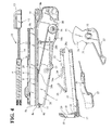
- a binding apparatus of the illustrated embodiment generally designated by reference character A generally includes a body 1 and a belt casing 3 having a continuous binding belt 2 drawably received therein while being wound and is adapted to bind an article or articles to be bound due to cooperation between the binding belt 2 and a fastener 4.
- the binding belt 2 is made of a flexible synthetic resin material and formed to have a continuous elongated configuration.
- the binding belt 2, as shown in Fig. 5A, is formed on a central portion of one of both side surfaces thereof defined in a longitudinal direction thereof with ruggedness or asperities 5 in a rack-like manner.
- the fastener 4 is made of a synthetic resin material and generally formed to have a rectangular parallelepiped configuration as shown in Figs. 5A and 5B. More specifically, the fastener 4 is formed with an insertion hole 6 through which the binding belt 2 is inserted. Also, the fastener 4 is provided on inner surfaces thereof opposite to each other with holding pawls 7 each adapted to be engaged with the asperities 5 of the binding belt 2.
- the body 1 of the binding apparatus A is provided therein with a belt passage 8 for permitting the binding belt 2 fed from the binding belt casing 3 to be guided from a rear end of the body 1 to a front end thereof therethrough and a fastener passage 9 for guiding a plurality of the fasteners 4 each adapted to fasten an end of the binding belt 2 therethrough while keeping the fasteners 4 arranged in a row.
- the belt passage 8 and fastener passage 9 are arranged so as to be substantially parallel to each other.
- the belt passage 8 and fastener passage 9 have front openings 8a and 9a formed on front ends thereof so as to be substantially vertically flush with each other, respectively.
- the belt passage 8 has a receiving element 10 for the fastener 4 formed at a lower portion of the front opening 8a thereof.
- the receiving element 10 is formed on a base portion thereof with a cutter insertion opening or groove 11.
- the fastener passage 9 has a fastener extrusion or push-out means 12 arranged therein in a manner to be detachable therefrom.
- the fastener push-out means 12 includes a lug 13, a rod-like push guide 14 connected to the lug 13 so as to outwardly extend therefrom, a spring 15 and a push block 16.
- the spring 15 and push block 16 are each mounted on the push guide 14 so as to be slidable thereon.
- the spring 15 is arranged between the push block 16 and the lug 13.
- the lug 13 includes a holding means (not shown) detachably held on the body 1.
- the push guide 14 is inserted through a rear opening 9b of the fastener passage 9 into the fastener passage 9 to abut the push block 16 against a rearmost fastener 4 of the plurality of fasteners 4 to forwardly force the fasteners 4 by elastic force of the spring 15.
- the body 1 of the binding apparatus A is provided with an actuation head 17 so as to be vertically actuated along a front surface of the body 1.
- the actuation head 17 is formed with an opening 18 so as to extend back and forth therethrough.
- the actuation head 17 is formed with a front wall 19 so as to be positioned above a front portion of the opening 18.
- the actuation head 17 has a fastener holder 20 arranged on a lower portion of a rear surface of the front wall 19.
- the actuation head 17 thus constructed is mounted on a front end of an actuation arm 21 which is formed to have a U-shape in section.
- the actuation arm 21 has a cutter 22 fixedly arranged on the front end thereof in a manner to be positioned immediately behind the actuation head 17.
- a member 25 which is made of a synthetic resin material and has a return spring 23 and a stopper 24 formed integrally therewith.
- the synthetic resin member 25 and actuation arm 21 are received in a space 26 defined below the belt passage 8 in the body 1.
- the synthetic resin member 25 and actuation arm 21 are each formed at a rear end thereof with a bearing hole 28a, which is engagedly fitted on a common support shaft 28b securely mounted between side walls of the body 1 defining the above-described space 26 therebetween so that the synthetic resin member 25 and actuation arm 21 may each be pivotally moved about the support shaft 28b.
- the actuation head 17 constructed as described above is arranged so as to be movable between a first position at which the fastener holder 20 is aligned with the front opening 9a of the fastener passage 9 and a second position at which the fastener holder 20 is aligned with the front opening 8a of the belt passage 8.
- the cutter 22 is configured so as to be moved along the front opening 8a of the belt passage 8 through the cutter insertion groove 11 of the receiving element 10 projectedly formed on the front end of the body 1 in association with the actuation head 17 when the actuation head 17 is moved from the second position to the first position.
- the stopper 24 is provided at a distal end thereof with a rugged portion 24a adapted to be engaged with the asperities 5 of the binding belt 2. Also, the stopper 24 is arranged below the belt passage 8 so as to retractably advance into the belt passage 8 through an opening 29 formed through a wall arranged between the belt passage 8 and the space 26.
- the binding apparatus A of the illustrated embodiment also includes an operation lever 27 arranged at a lower portion of the body 1 and pivotally supported on a shaft 57 mounted on the body 1.
- the operation lever 27 is provided on a proximal portion thereof with an upwardly extending projection 30.
- the operation lever 27 is so arranged that the projection 30 is abutted at an upper end thereof against a lower surface of the actuation arm 21.
- the binding belt casing 3 is provided therein with a binding belt receiving section of a circular shape. Also, the binding belt casing 3 is formed with a drawing opening through which the binding belt 2 is drawn out of the casing 3.
- the binding belt casing 3 is detachably mounted on the body 1.
- the binding apparatus A of the illustrated embodiment further includes a tightening mechanism constituted by a tightening lever 31 pivotally mounted on a lower portion of a rear region of the body 1.
- the tightening lever 31 is formed at a substantially intermediate portion thereof with an elongated hole 32 in a manner to vertically extend.
- the tightening lever 31 is integrally provided at a lower portion thereof with a lever section 33 and at an upper portion thereof with a fan-shaped section 34.
- the fan-shaped section 34 is provided at a distal end thereof with a gear portion 35.
- the gear portion 35 includes a plurality of teeth arranged on the distal end in an arcuate manner.
- the belt passage 8 is formed at a portion of a lower side thereof positionally corresponding to the gear portion 35 with an opening 8b.
- the opening 8b permits the asperities 5 of the binding belt 2 to be exposed therethrough, so that the asperities 5 may be engaged with the gear portion 35 through the opening 8b.
- the lever section 33 is arranged so as to extend outwardly of the body 1. Also, the elongated hole 32 of the tightening lever 31 is fitted therein with a support shaft 36 securely arranged between both side walls of the body 1, so that the tightening lever 31 may be vertically moved so as to access the belt passage 8 and to be away from the belt passage 8 and pivotally moved about the support shaft 36.
- the above-described opening 8b of the belt passage 8 is formed so as to arcuately extend in correspondence to the gear portion 35 of the tightening lever 31.
- the body 1 is provided therein with a guide 37 (Fig. 4) which functions to guide the binding belt 2 while arcuately bending it.
- the illustrated embodiment may be so configured that the side plates of the body 1 are each formed with an elongated hole and the tightening lever 31 is mounted thereon with a shaft pivotally fitted in the elongated hole.
- the support shaft 36 has a torsion coil spring 38 wound therearound.
- the torsion coil spring 38 is engaged at one end 38a thereof with a lower surface of the belt passage 8 of the body 1 and at the other end 38b thereof with the tightening lever 31.
- Such arrangement of the torsion coil spring 38 permits elastic force of the spring 38 to constantly downwardly urge the tightening lever 31, resulting in the tightening lever 31 being downwardly spaced from the belt passage 8.
- the torsion coil spring 38 is so arranged that the one end 38a is engaged with the belt passage 8 at a position defined in proximity to the actuation head 17 as compared with a distal end of the lever section 33 of the tightening lever 31.
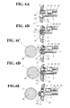
- the operation lever 27 is drawn up while being grasped together with the body 1 of the apparatus by a hand, to thereby pivotally move the actuation arm 21 against elastic force of the return spring 23.
- This causes the actuation head 17 to be moved to the first position (Fig. 6A), resulting in the fastener holder 20 of the actuation head 17 being positionally aligned with the front opening 9a of the fastener passage 9, so that a foremost fastener of the fasteners 4 may be forced by the fastener push-out means 12, to thereby enter the fastener holder 20 and be held therein.
- the return spring 23 causes the actuation arm 21 to be downwardly moved, so that the actuation head 17 is moved to the second position aligned with the front opening 8a of the belt passage 8.
- the fastener 4 is abuttedly received by the receiving element 10, so that the fastener 4 may be held at the above-described aligned position (Fig. 6B).
- the binding belt 2 is drawn out of the binding belt casing 3 and inserted into the belt passage 8 of the body 1, resulting in it being guided to a central region between the holding pawls 7 of the fastener 4.
- the binding belt 2 is fed through the binding belt insertion hole 6 of the fastener 4 and then delivered forwardly of the actuation head 17.
- the binding belt 2 is forwardly pulled and wound around an article 40 to be bound and then inserted at a distal end thereof through the insertion hole 6 of the fastener 4 in the fastener holder 20 of the actuation head 17 into the fastener 4 again, resulting in the asperities 5 of the binding belt 2 being held on the holding pawls 7 (Fig. 6C).
- the asperities 5 of the binding belt 2 and the holding pawls 7 of the fastener 4 are engaged with each other, resulting in the binding belt 2 being kept tightened to a certain degree.
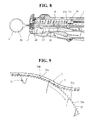
- the tightening lever 31 when the tightening lever 31 is upwardly pivotally moved as shown in Fig. 7A, the whole tightening lever 31 is upwardly moved with respect to the support shaft 36 against the torsion coil spring 38, to thereby engage the gear portion 35 of the fan-shaped section 34 with the asperities 5 of the binding belt 2. Also, the tightening lever 31 is further pivotally moved in a clockwise direction in Fig. 7A, so that the binding belt 2 is rearwardly pulled back, to thereby be further tightened.
- the gear portion 35 is formed to have an arcuate configuration, so that engagement between the gear portion 35 and the asperities 5 is stably ensured throughout pivotal movement of the tightening lever 31, to thereby effectively prevent damage to the gear portion 35 and asperities 5. Further, the tightening lever 31 utilizes a lever action, resulting in positive tightening of the binding belt 2 being ensured.
- the cutter 22 When the operation lever 27 is upwardly pivotally moved to move the actuation head 17 to the first position after the tightening operation, the cutter 22 is operated in association with such movement of the actuation head 17, to thereby be transferred through the cutter insertion groove 11 of the receiving element 10. This permits the cutter 22 to cut the binding belt 2, so that a portion of the binding belt 2 wound around the article 40 may be separated from the binding belt 2 as shown in Figs. 6D and 6E. This results in the binding operation being completed. Concurrently, the next fastener 4 is fed into the actuation head 17; so that when the actuation head 17 is returned to the second position, the fastener 4 is lowered onto the receiving element 10. This permits the binding apparatus A to be ready for the next binding operation.
- the gear portion 35 is preferably configured so that a surface 35a of each of teeth of the gear portion 35 engaged with the asperities 5 of the binding belt 2 extends in a radial direction of the gear portion 35 and a surface 35b thereof opposite to the surface 35a is inclined. Such configuration of the gear portion 35 facilitates release of the gear portion 35 from engagement with the asperities 5 of the binding belt 2 after the tightening.
- the tightening mechanism described above permits tightening of the binding belt 2 to be readily and positively attained without directly touching the binding belt 2 while being simplified in structure.
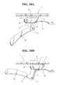
- a tightening lever 31 includes a lever section 42 pivotally mounted on a support shaft 41 of the body 1 of the binding apparatus and an actuation block 44 pivotally connected to a distal end of the lever section 42 through a shaft 43.
- the actuation block 44 is formed on an upper surface thereof with a gear portion 35.
- the shaft 43 of the actuation block 44 is formed with an elongated bearing hole 45 in a manner to obliquely extend.
- the actuation block 44 is so constructed that a rear end thereof is moved along an elastic guide plate 46 arranged in the body 1.
- the lever section 42 is elastically urged so as to be constantly kept at a lowered position as shown in Fig. 10A.
- Figs. 10A and 10B tightening of the binding belt 2 is carried out by vertically pivotally operating the tightening lever 31 while grasping it together with the body 1 by a hand.
- the rear end of the actuation block 44 is moved along the elastic guide plate 46 and a front end thereof is moved due to movement of the shaft 43 in the bearing hole 45, so that the gear portion 35 may be upwardly moved, to thereby be engaged with the asperities 5 of the binding belt 2 and rearwardly move the binding belt 2, to thereby tighten the binding belt 2.
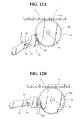
- the tightening mechanism may be modified in such a manner as shown in Figs. 11A and 11B.
- the modification is constructed so as to reciprocate a tightening lever 31 substantially in parallel to the belt passage 8.
- the body 1 of the binding apparatus is provided on a rear portion thereof with a grip la and formed therein with guide grooves 47 in parallel to the belt passage 8.
- Each of the guide grooves 47 is constituted by an upper groove section 47a and a lower groove section 47b which are circulatedly contiguous to each other, so that the guide groove 47 is formed to have a parallelogram-like shape.
- the guide groove 47 has a front angular end 48 somewhat upwardly positioned.
- the tightening lever 31 is constituted by a lever section 49 and a block 50 including a gear portion 35.
- the tightening lever 31 is provided on each of both sides thereof with a shaft 51, which is engagedly fitted in the guide groove 47, so that the tightening lever 31 may be not only pivotally moved but moved back and forth along the upper and lower groove sections 47a and 47b.
- the tightening lever 31 is maintained at a state indicated by dashed lines in Fig. 11A during non-use thereof.
- the tightening lever 31 is constantly forwardly urged by a spring (not shown).
- the shafts 51 are permitted to pass through the lower groove sections 47b, to thereby keep the gear portion 35 from being abutted against the asperities 5 of the binding belt 2.
- the shafts 51 are permitted to be stopped at a position somewhat above the front angular ends 48 of the guide grooves 47. Such operation is repeated to complete tightening of the binding belt 2.
- a further modification of the tightening mechanism is illustrated.
- the modification is configured in such a manner that a circular tightening gear 52 is rotatably supported on the body 1 of the apparatus and has a gear portion 52a thereof kept constantly engaged with the asperities 5 of the binding belt 2.
- a tightening lever 31 is mounted on a revolving shaft 56 of the tightening gear 52. Operation of tightening the binding belt 2 is carried out by rotating the tightening gear 52 through the tightening lever 31.
- the tightening lever 31 is mounted thereon with an actuation block 53 in a manner to be slidable in a longitudinal direction thereof.
- a gear portion 53a is formed on the actuation block 53.
- the actuation block 53 is elastically urged toward the tightening gear 52 by a spring (not shown) and formed with a holding element 54 engageable with a projection 55 provided on the tightening lever 31.
Applications Claiming Priority (2)
| Application Number | Priority Date | Filing Date | Title |
|---|---|---|---|
| JP2000048209 | 2000-02-24 | ||
| JP2000048209A JP3748504B2 (ja) | 2000-02-24 | 2000-02-24 | 結束装置 |
Publications (2)
| Publication Number | Publication Date |
|---|---|
| EP1127789A1 true EP1127789A1 (de) | 2001-08-29 |
| EP1127789B1 EP1127789B1 (de) | 2007-08-08 |
Family
ID=18570332
Family Applications (1)
| Application Number | Title | Priority Date | Filing Date |
|---|---|---|---|
| EP01103565A Expired - Lifetime EP1127789B1 (de) | 2000-02-24 | 2001-02-20 | Bindevorrichtung zum Spannen eines Bindestreifens |
Country Status (7)
| Country | Link |
|---|---|
| US (1) | US6527017B2 (de) |
| EP (1) | EP1127789B1 (de) |
| JP (1) | JP3748504B2 (de) |
| KR (1) | KR100887201B1 (de) |
| CN (1) | CN1212956C (de) |
| DE (1) | DE60129759T2 (de) |
| TW (1) | TW467842B (de) |
Cited By (2)
| Publication number | Priority date | Publication date | Assignee | Title |
|---|---|---|---|---|
| CN105905333A (zh) * | 2016-05-25 | 2016-08-31 | 宁波市创佳工业设计有限公司 | 一种联排扎带扣的安装进给机构 |
| CN105947325A (zh) * | 2016-05-25 | 2016-09-21 | 宁波市创佳工业设计有限公司 | 一种切带机构及使用该机构的联排扎带扣扎带机 |
Families Citing this family (8)
| Publication number | Priority date | Publication date | Assignee | Title |
|---|---|---|---|---|
| JP4695897B2 (ja) * | 2005-03-04 | 2011-06-08 | ヘラマンタイトン株式会社 | 結束引締め具 |
| JP4338695B2 (ja) * | 2005-10-31 | 2009-10-07 | 中国電力株式会社 | 結束装置 |
| CN108366934B (zh) * | 2015-12-18 | 2021-09-07 | 莱雅公司 | 在施加期间具有颜色转变的组合物 |
| CN106051261B (zh) * | 2016-06-02 | 2018-03-09 | 宁波市艾柯特工具科技发展有限公司 | 一种扎带机的执行机构 |
| JP1572313S (de) * | 2016-06-15 | 2017-03-27 | ||
| CN107140249B (zh) * | 2017-05-22 | 2019-06-28 | 彭州市长庆全成技术开发有限公司 | 拉紧器 |
| CN110952529B (zh) * | 2019-11-29 | 2021-04-13 | 通号建设集团第一工程有限公司 | 变截面的地下连续墙的施工方法 |
| JP1695943S (de) | 2020-11-30 | 2021-09-27 |
Citations (5)
| Publication number | Priority date | Publication date | Assignee | Title |
|---|---|---|---|---|
| FR2223141A1 (de) * | 1973-03-26 | 1974-10-25 | Nifco Inc | |
| JPH043933Y2 (de) | 1987-07-24 | 1992-02-06 | ||
| JPH043935Y2 (de) | 1987-07-24 | 1992-02-06 | ||
| JPH043934Y2 (de) | 1987-07-24 | 1992-02-06 | ||
| JPH043936Y2 (de) | 1987-07-24 | 1992-02-06 |
Family Cites Families (10)
| Publication number | Priority date | Publication date | Assignee | Title |
|---|---|---|---|---|
| US2569623A (en) * | 1948-02-04 | 1951-10-02 | Acme Steel Co | Strap stretching device |
| GB965784A (en) * | 1961-11-17 | 1964-08-06 | Atomic Energy Authority Uk | Cable strapping tools |
| US3645302A (en) * | 1970-03-19 | 1972-02-29 | Panduit | Strap installation tool |
| US4407692A (en) * | 1981-05-29 | 1983-10-04 | Monarch Marking Systems, Inc. | Hand-held electrically selectable labeler |
| JPS633933A (ja) * | 1986-06-24 | 1988-01-08 | Honda Motor Co Ltd | 真空ラミネ−ト方法 |
| JP2572664B2 (ja) * | 1990-04-13 | 1997-01-16 | 三ツ星ベルト株式会社 | エンドレスベルトの製造方法 |
| JPH043934U (de) * | 1990-04-24 | 1992-01-14 | ||
| JPH043936U (de) * | 1990-04-27 | 1992-01-14 | ||
| JPH0511152Y2 (de) * | 1990-04-27 | 1993-03-18 | ||
| DE4212789C1 (de) * | 1992-04-16 | 1993-09-09 | A. Raymond Gmbh & Co. Kg, 7850 Loerrach, De |
-
2000
- 2000-02-24 JP JP2000048209A patent/JP3748504B2/ja not_active Expired - Fee Related
-
2001
- 2001-02-16 US US09/785,093 patent/US6527017B2/en not_active Expired - Lifetime
- 2001-02-20 DE DE60129759T patent/DE60129759T2/de not_active Expired - Lifetime
- 2001-02-20 EP EP01103565A patent/EP1127789B1/de not_active Expired - Lifetime
- 2001-02-21 TW TW090103871A patent/TW467842B/zh not_active IP Right Cessation
- 2001-02-22 KR KR1020010008869A patent/KR100887201B1/ko active IP Right Grant
- 2001-02-24 CN CNB011165189A patent/CN1212956C/zh not_active Expired - Lifetime
Patent Citations (5)
| Publication number | Priority date | Publication date | Assignee | Title |
|---|---|---|---|---|
| FR2223141A1 (de) * | 1973-03-26 | 1974-10-25 | Nifco Inc | |
| JPH043933Y2 (de) | 1987-07-24 | 1992-02-06 | ||
| JPH043935Y2 (de) | 1987-07-24 | 1992-02-06 | ||
| JPH043934Y2 (de) | 1987-07-24 | 1992-02-06 | ||
| JPH043936Y2 (de) | 1987-07-24 | 1992-02-06 |
Cited By (3)
| Publication number | Priority date | Publication date | Assignee | Title |
|---|---|---|---|---|
| CN105905333A (zh) * | 2016-05-25 | 2016-08-31 | 宁波市创佳工业设计有限公司 | 一种联排扎带扣的安装进给机构 |
| CN105947325A (zh) * | 2016-05-25 | 2016-09-21 | 宁波市创佳工业设计有限公司 | 一种切带机构及使用该机构的联排扎带扣扎带机 |
| CN105905333B (zh) * | 2016-05-25 | 2017-12-05 | 宁波市艾柯特工具科技发展有限公司 | 一种联排扎带扣的安装进给机构 |
Also Published As
| Publication number | Publication date |
|---|---|
| KR100887201B1 (ko) | 2009-03-06 |
| DE60129759D1 (de) | 2007-09-20 |
| KR20010085462A (ko) | 2001-09-07 |
| EP1127789B1 (de) | 2007-08-08 |
| JP3748504B2 (ja) | 2006-02-22 |
| JP2001240017A (ja) | 2001-09-04 |
| CN1323720A (zh) | 2001-11-28 |
| CN1212956C (zh) | 2005-08-03 |
| US6527017B2 (en) | 2003-03-04 |
| US20010039976A1 (en) | 2001-11-15 |
| TW467842B (en) | 2001-12-11 |
| DE60129759T2 (de) | 2007-12-27 |
Similar Documents
| Publication | Publication Date | Title |
|---|---|---|
| US6966476B2 (en) | Integrated check pawl, last nail-retaining, and dry fire lock-out mechanism for fastener-driving tool | |
| US8006881B2 (en) | Magazines in fastener driving tools | |
| US5322189A (en) | Fastener feeding mechanism in fastener driving device | |
| US4517863A (en) | Successive screw feeder driver | |
| EP1127789B1 (de) | Bindevorrichtung zum Spannen eines Bindestreifens | |
| JP3333114B2 (ja) | 連続ビス締付機 | |
| KR20080057301A (ko) | 로터리 그리퍼 및 볼 세팅 장치를 구비한 금속 타이 툴 | |
| US6467172B1 (en) | Plastic pipe cutting device | |
| US6244491B1 (en) | Hand held stapler | |
| GB2311954A (en) | Wire cassette for a stitching machine | |
| JP4046717B2 (ja) | 工具ヘッド | |
| JPS6238215B2 (de) | ||
| US4762262A (en) | Side-fed stapler | |
| JP3793303B2 (ja) | 固着具打込機の給送装置 | |
| US4410123A (en) | Wire stitching machine head | |
| US7343954B2 (en) | Label applying apparatus | |
| JP4990015B2 (ja) | ねじ締め機のねじ供給装置 | |
| JP3598767B2 (ja) | 電動ホッチキスにおけるカートリッジの脱着機構 | |
| JP3947058B2 (ja) | 固着具打込機の固着具送り装置 | |
| JP4389077B2 (ja) | リムーバ | |
| JP3600019B2 (ja) | 釘打機におけるマガジン | |
| US20040020023A1 (en) | Clip driver | |
| JP5020693B2 (ja) | ねじ供給装置、及びそのねじ供給装置を備えるねじ締め機 | |
| JPH043939Y2 (de) | ||
| JPH043933Y2 (de) |
Legal Events
| Date | Code | Title | Description |
|---|---|---|---|
| PUAI | Public reference made under article 153(3) epc to a published international application that has entered the european phase |
Free format text: ORIGINAL CODE: 0009012 |
|
| AK | Designated contracting states |
Kind code of ref document: A1 Designated state(s): AT BE CH CY DE DK ES FI FR GB GR IE IT LI LU MC NL PT SE TR Kind code of ref document: A1 Designated state(s): DE FR GB IT |
|
| AX | Request for extension of the european patent |
Free format text: AL;LT;LV;MK;RO;SI |
|
| 17P | Request for examination filed |
Effective date: 20011124 |
|
| AKX | Designation fees paid |
Free format text: DE FR GB IT |
|
| GRAP | Despatch of communication of intention to grant a patent |
Free format text: ORIGINAL CODE: EPIDOSNIGR1 |
|
| GRAS | Grant fee paid |
Free format text: ORIGINAL CODE: EPIDOSNIGR3 |
|
| GRAA | (expected) grant |
Free format text: ORIGINAL CODE: 0009210 |
|
| AK | Designated contracting states |
Kind code of ref document: B1 Designated state(s): DE FR GB IT |
|
| REG | Reference to a national code |
Ref country code: GB Ref legal event code: FG4D |
|
| REF | Corresponds to: |
Ref document number: 60129759 Country of ref document: DE Date of ref document: 20070920 Kind code of ref document: P |
|
| ET | Fr: translation filed | ||
| PLBE | No opposition filed within time limit |
Free format text: ORIGINAL CODE: 0009261 |
|
| STAA | Information on the status of an ep patent application or granted ep patent |
Free format text: STATUS: NO OPPOSITION FILED WITHIN TIME LIMIT |
|
| 26N | No opposition filed |
Effective date: 20080509 |
|
| REG | Reference to a national code |
Ref country code: FR Ref legal event code: PLFP Year of fee payment: 16 |
|
| REG | Reference to a national code |
Ref country code: FR Ref legal event code: PLFP Year of fee payment: 17 |
|
| REG | Reference to a national code |
Ref country code: FR Ref legal event code: PLFP Year of fee payment: 18 |
|
| PGFP | Annual fee paid to national office [announced via postgrant information from national office to epo] |
Ref country code: FR Payment date: 20191223 Year of fee payment: 20 |
|
| PGFP | Annual fee paid to national office [announced via postgrant information from national office to epo] |
Ref country code: IT Payment date: 20200211 Year of fee payment: 20 Ref country code: GB Payment date: 20191223 Year of fee payment: 20 Ref country code: DE Payment date: 20191220 Year of fee payment: 20 |
|
| REG | Reference to a national code |
Ref country code: DE Ref legal event code: R071 Ref document number: 60129759 Country of ref document: DE |
|
| REG | Reference to a national code |
Ref country code: GB Ref legal event code: PE20 Expiry date: 20210219 |
|
| PG25 | Lapsed in a contracting state [announced via postgrant information from national office to epo] |
Ref country code: GB Free format text: LAPSE BECAUSE OF EXPIRATION OF PROTECTION Effective date: 20210219 |