EP1127787A2 - Lastenabwurf-Plattform zur Dämpfung von Lasten beim Lastenabwurf - Google Patents
Lastenabwurf-Plattform zur Dämpfung von Lasten beim Lastenabwurf Download PDFInfo
- Publication number
- EP1127787A2 EP1127787A2 EP01103620A EP01103620A EP1127787A2 EP 1127787 A2 EP1127787 A2 EP 1127787A2 EP 01103620 A EP01103620 A EP 01103620A EP 01103620 A EP01103620 A EP 01103620A EP 1127787 A2 EP1127787 A2 EP 1127787A2
- Authority
- EP
- European Patent Office
- Prior art keywords
- loads
- plate
- load transfer
- transfer platform
- load
- Prior art date
- Legal status (The legal status is an assumption and is not a legal conclusion. Google has not performed a legal analysis and makes no representation as to the accuracy of the status listed.)
- Withdrawn
Links
- 230000035939 shock Effects 0.000 title 1
- 238000013016 damping Methods 0.000 claims abstract description 25
- 239000004744 fabric Substances 0.000 claims abstract description 17
- 230000000694 effects Effects 0.000 claims description 3
- 238000000151 deposition Methods 0.000 description 2
- 230000000717 retained effect Effects 0.000 description 2
- 239000003351 stiffener Substances 0.000 description 2
- 230000001419 dependent effect Effects 0.000 description 1
- 238000006073 displacement reaction Methods 0.000 description 1
- 238000005516 engineering process Methods 0.000 description 1
- 238000000034 method Methods 0.000 description 1
- 230000035699 permeability Effects 0.000 description 1
Images


Classifications
-
- B—PERFORMING OPERATIONS; TRANSPORTING
- B64—AIRCRAFT; AVIATION; COSMONAUTICS
- B64D—EQUIPMENT FOR FITTING IN OR TO AIRCRAFT; FLIGHT SUITS; PARACHUTES; ARRANGEMENT OR MOUNTING OF POWER PLANTS OR PROPULSION TRANSMISSIONS IN AIRCRAFT
- B64D1/00—Dropping, ejecting, releasing or receiving articles, liquids, or the like, in flight
- B64D1/02—Dropping, ejecting, or releasing articles
- B64D1/08—Dropping, ejecting, or releasing articles the articles being load-carrying devices
- B64D1/14—Absorbing landing shocks
Definitions
- the invention relates to a load shedding platform for damping loads when Load shedding from aircraft that take place after dropping until touchdown an umbrella system is worn.
- the load transfer platform according to the invention has the inventive Solution an activatable damping mechanism that ensures that even sensitive loads can be landed without damage.
- the Load shedding platform is easy to handle after landing, so the load can be easily removed from the platform.
- Another advantage is that the load transfer platform according to the invention is reusable.
- the load transfer platform according to the invention shown in FIGS. 1 to 6 1 becomes after it has been dropped from the aircraft, i.e. also after a first Flight phase, carried by an umbrella system until touchdown on the ground.
- the Umbrella system can be a self-controlling or remote-controlled paraglider system or a round cap system with one or more umbrellas. On such a screen system is not shown in the figures.
- the load transfer platform 1 has a lower plate 3 and an upper plate 5 on.
- the load transfer platform 1 has a lower plate 3 and an upper plate 5 on.
- a coordinate system 7 is specified which shows the X or Longitudinal direction, the Y or side direction and the Z or height direction Are defined.
- a screen system is attached to the top plate 5 in the usual way, so that the screen extended after dropping off from the top plate 5 seen from the positive y direction.
- the bottom 3 and the top 5 plate are connected by a scissor linkage 9 and moved together.
- the scissors linkage 9 is such that this thrust, d. H. Absorbs forces in the X / Y plane.
- Such forces can thereby impact the load transfer platform according to the invention does not cause the upper plate 5 moves in the X or Y direction to the lower plate 3 and that entire load transfer platform 1 formed when landing.
- the scissors linkage 9 from a first pair of struts 11 with a first Strut 11a and a second strut 11b and a second pair of struts 12 formed with a first strut 12a and a second strut 12b. It can at least one of the strut pairs 11 and 12 transverse to the scissors movement a stiffener 13 may be reinforced to the load transfer platform 1 on impact stabilize against the thrust.
- the respective first strut 11a, 12a is with the respectively associated second strut 11b or 12b via a center provided pivot bearing 14, 15 rotatably connected.
- the two struts one Strut pairs each run parallel to one another, the two struts 11a, 11b and 12a, 12b of a pair of struts 11 and 12 respectively on opposite Side edges of the lower plate 3 or upper plate 5 run.
- At the front side 21 for load transfer platform 1 are the respective ends of the first 11 and second 12 strut pairs in pivot bearings 21 on the lower 3 and upper 5 plate rotatably mounted.
- each pair of struts 11 and 12 each stored in a backdrop, in pairs on the one end the lower plate 3 and provided at the respective end of the upper plate 5 are.
- the length share of the individual struts is the Strut pairs 11, 12 which are caused by the relative Z displacement of the upper plate 5 to the lower plate 3 occurs, balanced.
- first strut 11a of the first pair of struts 11 is with its one end in a first pivot bearing 31a rotatable on the upper plate 5 stored and with its other end in the scenery 32a on the lower plate 3rd rotatable as well as limited longitudinally displaceable.
- the analog is second strut 11b of the first pair of struts 11 by means of a bearing 31b on the upper plate 5 and by means of a link 32b (not shown) on the lower plate 3 stored.
- the first strut 12a of the second pair of struts 12 and the second The strut 12b of the second pair of struts 12 has one end in each a respective pivot bearing 33a and 33b on the lower plate 3 and with their other ends limited in corresponding scenes 34a and 34b longitudinally displaceable and rotatably mounted on the upper plate 5.
- the pivot bearings 31a, 31b, 33a, 33b can be exchanged for the scenes 32a, 32b, 34a, 34b be as long as the functional principle described is retained.
- the scissor linkage 9 described thus makes the lower plate 3 with respect to the upper plate 5 in parallel movement apart or into one another mobile.
- the scissors linkage 9 can also be different according to the prior art be formed as long as the described mode of operation is retained.
- the scenes 32a, 32b, 34a, 34b can be replaced by rotary bearings if the struts of the strut pairs 11, 12 telescopically, for example are formed by means of spring dampers.
- the scissors linkage 9 causes the upper plate 5 compared to lower plate 3 in the X / Y plane not are mutually displaceable.
- the optional stiffening provides the scissors linkage 9 additional stability.
- the top 5 and the bottom 3 The plates can only be moved against each other in the Z direction.
- damper elements 30 are attached between the top 5 and the lower plate 3.
- a total of 4 Damper elements 30a, 30b, 30c, 30d are provided, which are symmetrical between the lower 3 and the upper plate 5 are arranged.
- Each damper element 30 has an upper fastening ring 31 and one lower mounting ring 32, each by means of fasteners 33 the upper plate 5 and the lower plate 4 are attached.
- At the top 31 and the lower mounting ring 32 is a circumference thereof air-permeable or air-impermeable fabric 35 in the form of a Fastened fabric jacket that the of the mounting rings 31, 32nd bounded areas of the top 5 and bottom 3 plate between these one Forms airspace. Since the plates 3, 5 can be moved apart, the size of the Lucastaums from the relative position of the plates 3, 5. in the the expanded state of the plates 3, 5 forms the tissue 35 rotationally symmetrical structure.
- the mounting rings 31 and 32 are there almost airtight on the top 5 or bottom 3 plate.
- the passage ring 37 has several On the circumference evenly distributed through holes 39 through which at Spread the lower 3 and upper plate 5 air in the then inflow air space and when plates 3, 5 move together Air can escape.
- the passage ring 37 can be centered between the upper 31st and the lower 32 mounting ring.
- the Passage ring 37 also near the upper 31 or lower mounting ring 32 or be arranged directly on this.
- the last alternative is in FIGS. 9 and 11.
- the at least one through hole 39 can also be opened another way on the damper element 30, that is not on the passage ring 37, be provided as long as the function described is fulfilled. They can also Fastening rings 31, 32 are omitted if the fabric jacket 35 on the plates 3, 5 directly attached, e.g. is glued on.
- the fabric 35 according to FIG. 7 is composed of several parts which are vulcanized overlapping each other.
- the resulting ones Overlap stiffeners are preferably longitudinal, i.e. in the direction the relative movements of the lower 3 and upper 5 plates. This allows achieve predictable folding behavior just like the bellows cylinder. However, it can also be folded, as shown in FIG. 9. in the when extended, the fabric 35 then forms a so-called Bellows cylinder.
- the disadvantage of this embodiment is that a bellows cylinder costly and, in some embodiments, less robust than the compared alternatives of Figures 7, 8 and 12, 13.
- the fabric 35 can also be smooth and uniform across the height and circumference, i.e. without Fold and be made in one piece ( Figure 11). The least effort results in the fabric according to FIG. 11, but that is not predictable folding behavior when retracting the invention Has damper elements 30.
- the load transfer platform 1 has on its upper plate 5 several fittings 41 to the load to be deposited (not shown) on the to fix the upper plate 5 or to pull it firmly.
- the fittings 41 can in Form of eyelets may be arranged and are preferably evenly along the Side edges 42 of the top plate 5 arranged. Furthermore, along the Side edges 42 of the top plate 5 further fasteners or eyelets for Potentiation of the load transfer platform 1 can be provided.
- the load transfer platform 1 is designed so that it can be shared with others Load transfer platforms of the same design can be coupled together.
- Load transfer platforms of the same design can be coupled together.
- FIGS. 14 and 15 show how two Load transfer platforms 1 are coupled together according to the invention.
- the load transfer platform 1 is used alone or in Combination with at least one further load transfer platform 1 together dropped from the aircraft with the load to be set down on it.
- a screen connected to the top plate 5 or Umbrella system opened with usual means. Then then on the top plate 5 Braking force of the screen or the screens acts in the positive y direction the upper 5 and the lower 3 plate pulled apart. This can only happen after unlocking one between the bottom 3 and the top 5 plate acting locking device (not shown).
- damper elements can improve between the bottom 3 and the top 5 plate Spring elements, e.g. Gas pressure springs can be arranged.
Landscapes
- Engineering & Computer Science (AREA)
- Aviation & Aerospace Engineering (AREA)
- Vibration Dampers (AREA)
- Vibration Prevention Devices (AREA)
- Refuge Islands, Traffic Blockers, Or Guard Fence (AREA)
Abstract
Description
- Figur 1 eine perspektivische Darstellung der erfindungsgemäßen Lastenabsetz-Plattform im auseinandergefahrenen Zustand, den die Plattform kurz vor dem Auftreffen am Boden zur Gewährleistung einer ausreichenden Dämpfung der mit geführten Last aufweisen muß, wobei die obere Platte durchsichtig gezeichnet ist
- Figur 2 eine perspektivische Darstellung der Lastenabsetz-Plattform in ihrem eingefahrenen Zustand, wobei die obere Platte durchsichtig gezeichnet ist,
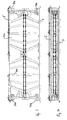
- Figur 3 eine Ansicht der Lastenabsetz-Plattform von vorne oder in X-Richtung gesehen, wobei sich die Lastenabsetz-Plattform in ihrem ausgefahrenen Zustand der Figur 1 befindet, mit einer ersten Ausführungsform von Dämpfungselementen,
- Figur 4 die Lastenabsetz-Plattform der Figur 3 in ihrem eingefahrenen Zustand ebenfalls von vorne gesehen,
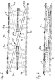
- Figur 5 eine Ansicht der Lastenabsetz-Plattform der Figur 1 von der Seite oder in Y-Richtung gesehen in ihrem ausgefahrenen Zustand mit der ersten Ausführungsform von Dämpfungselementen,
- Figur 6 die Lastenabsetz-Plattform in der Darstellung der Figur 5 in ihrem eingefahrenen Zustand,
- Figur 7 das Dämpfungselement in einer ersten Ausführungsform im ausgefahrenen Zustand,
- Figur 8 das Dämpfungselement der Figur 7 in seinem eingefahrenen Zustand,
- Figur 9 eine zweite Ausführungsform eines Dämpfungselements in ihrem ausgefahrenen Zustand,
- Figur 10 das Dämpfungselement der Figur 9 in seinem eingefahrenen Zustand,
- Figur 11 eine dritte Ausführungsform des Dämpfungselements in seinem ausgefahrenen Zustand,
- Figur 12 das Dämpfungselement der Figur 11 in seinem eingefahrenen Zustand,
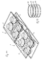
- Figur 13 verschiedene Varianten des Luftdurchlassrings, der in den erfindungsgemäßen Dämpfungselementen verwendet wird,
- Figur 14 eine Kombination von zwei erfindungsgemäßen Lastenabsetz-Plattformen zum Absetzen in größere Lasten.
Claims (9)
- Lastenabsetz-Plattform (1) zur Dämpfung von Lasten beim Lastenabwurf mit einer oberen Platte (5) zur Aufnahme der Last und mit einer unteren Bodenaufsetzplatte (3), wobei zwischen der oberen Platte (5) und der Bodenaufsetzplatte (3) zumindest ein Luftdämpferelement (30) angeordnet ist mit einem einen Innenraum ausbildenden Gewebemante (35), welcher an der oberen Platte (5) einerseits und an der Bodenaufsetzplatte (3) andererseits befestigt ist und mit seitlichen Durchlassöffnungen (39), wobei das Volumen des Innenraumes sich in Abhängigkeit der relativen Lage der oberen Platte (5) zur Bodenaufsetzplatte (3) verändert, so dass Luft einströmt, wenn sich der Abstand der Platten voneinander vergrößert und Luft zur Erzielung der Dämpfungswirkung aus dem Innenraum verdrängt wird, wenn die Platten zusammengedrückt werden, dadurch gekennzeichnet, dass die obere Platte (5) und die Bodenaufsetzplatte (7) mittels eines Scherengestänges (9) miteinander so verbunden sind, dass die beiden Platten nur in paralleler Lage, in vertikaler Richtung gegeneinander beweglich sind und wobei die obere Platte mit einem sich beim Lastenabwurf in der Flugphase öffnenden Schirm verbunden ist, dessen sich auf die obere Platte (5) auswirkende Bremskraft zum Auseinanderziehen der Platten (3, 5) eingesetzt wird.
- Lastenabsetz-Plattform zur Dämpfung von Lasten beim Lastenabwurf nach Anspruch 1, dadurch gekennzeichnet, dass der zumindest eine Schirm ein selbststeuerndes oder ferngesteuertes Gleitschirmsystem ist.
- Lastenabsetz-Plattform zur Dämpfung von Lasten beim Lastenabwurf nach Anspruch 1, dadurch gekennzeichnet, dass der zumindest eine Schirm ein Rundkappensystem mit einem Schirm oder mehreren Schirmen ist.
- Lastenabsetz-Plattform zur Dämpfung von Lasten beim Lastenabwurf nach einem der voranstehenden Ansprüche, dadurch gekennzeichnet, dass das Luftdämpferelement (30) ein rotationssymmetrischer Hohlkörper ist, so dass die von seinem Gewebemante (35) umgrenzten Stirnflächen an den Platten (3, 5) Kreisflächen sind und der Mantel einen Durchlassring (37) aufweist, in dem die Durchlassöffnungen (39) vorgesehen sind.
- Lastenabsetz-Plattform zur Dämpfung von Lasten beim Lastenabwurf nach einem der voranstehenden Ansprüche, dadurch gekennzeichnet, dass der Gewebemantel (35) an der oberen (5) und an der unteren (3) Platte mittels jeweils einen Befestigungsrings (31, 32) befestigt und einheitlich über den Umfang und die Höhe des Dämpferelements (30) ausgebildet ist und daß der Durchlaßring (37) neben einem ersten der Befestigungsringe (31,32) angeordnet ist.
- Lastenabsetz-Plattform zur Dämpfung von Lasten beim Lastenabwurf nach dem Anspruch 5, dadurch gekennzeichnet, dass ein weiterer Durchlaßring (37) an dem zweiten der Befestigungsringe (31,32) vorgesehen ist.
- Lastenabsetz-Plattform zur Dämpfung von Lasten beim Lastenabwurf nach einem der voranstehenden Ansprüche, dadurch gekennzeichnet, daß das Dämpferelement (30) als Faltenbalg-Zylinder ausgebildet ist.
- Lastenabsetz-Plattform zur Dämpfung von Lasten beim Lastenabwurf nach einem der Ansprüche 1 bis 6, dadurch gekennzeichnet, dass das Gewebe (35) aus Teilen gebildet ist, die gegeneinander überlappend auf vulkanisiert sind, um beim Zusammenfahren des Dämpferelements (30) ein vorbestimmtes Zusammenlegen des Gewebes (35) zu erreichen, wobei der Durchlaßring (37) mittig zwischen dem oberen (31) und dem unteren (32) Befestigungsring angeordnet ist.
- Lastenabsetz-Plattform nach einem der voranstehenden Ansprüche, dadurch gekennzeichnet, dass zumindest eine der Platten (3,5) an zumindest einem ihrer Seitenränder mit Befestigungsmitteln versehen ist, um daran eine weitere Lastenabsetz-Plattform zu befestigen.
Applications Claiming Priority (2)
| Application Number | Priority Date | Filing Date | Title |
|---|---|---|---|
| DE10008915A DE10008915B4 (de) | 2000-02-25 | 2000-02-25 | Lastenabsetz-Plattform zur Dämpfung von Lasten beim Lastenabwurf |
| DE10008915 | 2000-02-25 |
Publications (2)
| Publication Number | Publication Date |
|---|---|
| EP1127787A2 true EP1127787A2 (de) | 2001-08-29 |
| EP1127787A3 EP1127787A3 (de) | 2003-01-02 |
Family
ID=7632411
Family Applications (1)
| Application Number | Title | Priority Date | Filing Date |
|---|---|---|---|
| EP01103620A Withdrawn EP1127787A3 (de) | 2000-02-25 | 2001-02-22 | Lastenabwurf-Plattform zur Dämpfung von Lasten beim Lastenabwurf |
Country Status (3)
| Country | Link |
|---|---|
| US (1) | US6431088B2 (de) |
| EP (1) | EP1127787A3 (de) |
| DE (1) | DE10008915B4 (de) |
Cited By (2)
| Publication number | Priority date | Publication date | Assignee | Title |
|---|---|---|---|---|
| EP3250438A4 (de) * | 2015-01-28 | 2018-04-04 | Fuelie Systems, Inc. | Tragbare kraftstofflagerungsvorrichtung |
| US11840444B2 (en) | 2018-03-16 | 2023-12-12 | Fuelie Systems, Inc. | Fuel storage and dispensing device |
Families Citing this family (15)
| Publication number | Priority date | Publication date | Assignee | Title |
|---|---|---|---|---|
| US7631848B2 (en) | 2001-06-08 | 2009-12-15 | Draper, Inc. | Projector lift |
| WO2006009225A1 (ja) * | 2004-07-23 | 2006-01-26 | Asahi Glass Company, Limited | 板状体梱包箱、板状体搬送方法及び板状体積載・取出し方法 |
| US8522694B2 (en) | 2008-06-20 | 2013-09-03 | Oria Collapsibles, Llc | Structural supporting pallet construction with improved perimeter impact absorbing capabilities |
| US8701569B2 (en) | 2008-06-20 | 2014-04-22 | Oria Collapsibles, Llc | Pallet design with structural reinforcement |
| US8418631B2 (en) * | 2010-08-26 | 2013-04-16 | Oria Collapsibles, Llc | Pallet design with buoyant characteristics |
| US9670039B1 (en) | 2011-06-03 | 2017-06-06 | Draper, Inc. | Projector lift |
| US8864080B2 (en) * | 2012-01-31 | 2014-10-21 | Roy L Fox, Jr. | Expendable aerial delivery system |
| US9675508B2 (en) * | 2014-08-25 | 2017-06-13 | Shawn Anthony Hall | Apparatus for lifting a chair |
| GB2530287B (en) * | 2014-09-17 | 2017-10-04 | Airborne Systems Ltd | Aerial delivery platform with an elastically deformable structure |
| CN106347814A (zh) * | 2016-09-30 | 2017-01-25 | 松冷(武汉)科技有限公司 | 一种减振托盘 |
| US10427788B1 (en) * | 2016-11-17 | 2019-10-01 | U.S. Government As Represented By The Secretary Of The Army | Airdrop platform integrated outrigger |
| KR101910955B1 (ko) * | 2018-04-27 | 2018-10-23 | 주식회사 대한폴리머 | 고무튜브와 스폰지볼을 이용한 완충형 파렛트 |
| US10583960B2 (en) * | 2018-06-22 | 2020-03-10 | International Business Machines Corporation | Selectively height adjustable shipping pallet |
| KR102001023B1 (ko) * | 2019-01-25 | 2019-07-17 | 이건승 | 중량에 따른 자동 압력 조절이 가능한 진동 저감형 파레트 |
| RU2727534C1 (ru) * | 2019-08-16 | 2020-07-22 | Федеральное государственное казенное военное образовательное учреждение высшего образования "Рязанское гвардейское высшее воздушно-десантное ордена Суворова дважды Краснознаменное командное училище имени генерала армии В.Ф. Маргелова" Министерства обороны Российской Федерации | Парашютная платформа |
Family Cites Families (16)
| Publication number | Priority date | Publication date | Assignee | Title |
|---|---|---|---|---|
| US2712913A (en) * | 1953-08-21 | 1955-07-12 | Staniey Aviat Corp | Aerial drop equipment |
| GB790844A (en) * | 1955-05-20 | 1958-02-19 | Ca Nat Research Council | Shock absorber |
| US3015470A (en) * | 1958-07-25 | 1962-01-02 | Roy R Patchen | Construction jack |
| FR1230569A (fr) * | 1959-04-01 | 1960-09-16 | Procédé pour le largage de charges aériennes, et dispositif amortisseur pour sa mise en oeuvre | |
| FR1234194A (fr) * | 1959-05-11 | 1960-10-14 | Callou & Cie Sa | Dispositif amortisseur d'atterrissage pour matériels parachutés |
| GB937049A (en) * | 1960-10-07 | 1963-09-18 | Gq Parachute Comp Ltd | Improvements in shock-absorbing devices |
| US3276530A (en) * | 1965-04-23 | 1966-10-04 | Fruehauf Corp | Load platform supported on air cushion |
| US3351027A (en) * | 1966-03-23 | 1967-11-07 | Lockheed Aircraft Corp | Shock resistant, vibration isolating platform |
| US3440976A (en) * | 1967-03-02 | 1969-04-29 | Valyi Emery I | Inflatable pallets |
| US3446469A (en) * | 1967-11-14 | 1969-05-27 | Us Navy | Scissor shock platform |
| FR96031E (fr) * | 1968-10-23 | 1972-05-19 | Bertin & Cie | Dispositif perfectionne pour l'atterissage de charges parachutées. |
| DE2358893C3 (de) * | 1973-11-27 | 1980-10-16 | Dr.Ing.H.C. F. Porsche Ag, 7000 Stuttgart | Transport- und Absetzpalette |
| DE2507709A1 (de) * | 1975-02-22 | 1976-09-02 | Brueggemann & Brand Kg | Palette zur aufnahme von ladegut |
| DE3024551C2 (de) * | 1980-06-28 | 1986-10-16 | Autoflug Gmbh, 2084 Rellingen | Ventil für einen luftgefüllten Landestoßdämpfer |
| US5105746A (en) * | 1990-07-19 | 1992-04-21 | E. I. Du Pont De Nemours And Company | Interlocking pallet |
| DE19708159C2 (de) * | 1997-02-28 | 2001-01-25 | Daimlerchrysler Aerospace Ag | Verfahren zur Verhinderung des Überschlagens bei der Landung eines Luft- oder Raumfahrtgerätes |
-
2000
- 2000-02-25 DE DE10008915A patent/DE10008915B4/de not_active Expired - Fee Related
-
2001
- 2001-02-22 EP EP01103620A patent/EP1127787A3/de not_active Withdrawn
- 2001-02-26 US US09/792,051 patent/US6431088B2/en not_active Expired - Fee Related
Non-Patent Citations (1)
| Title |
|---|
| None |
Cited By (3)
| Publication number | Priority date | Publication date | Assignee | Title |
|---|---|---|---|---|
| EP3250438A4 (de) * | 2015-01-28 | 2018-04-04 | Fuelie Systems, Inc. | Tragbare kraftstofflagerungsvorrichtung |
| US10683199B2 (en) | 2015-01-28 | 2020-06-16 | Fuelie Systems, Inc. | Portable fuel storage device |
| US11840444B2 (en) | 2018-03-16 | 2023-12-12 | Fuelie Systems, Inc. | Fuel storage and dispensing device |
Also Published As
| Publication number | Publication date |
|---|---|
| EP1127787A3 (de) | 2003-01-02 |
| DE10008915A1 (de) | 2001-09-13 |
| US6431088B2 (en) | 2002-08-13 |
| DE10008915B4 (de) | 2004-07-22 |
| US20010050035A1 (en) | 2001-12-13 |
Similar Documents
| Publication | Publication Date | Title |
|---|---|---|
| DE10008915B4 (de) | Lastenabsetz-Plattform zur Dämpfung von Lasten beim Lastenabwurf | |
| DE3026409C2 (de) | Flügelleitwerk für ein langgestrecktes Geschoß | |
| DE69404855T2 (de) | Entfaltbarer flügel | |
| EP0653350B1 (de) | Container für den Lufttransport | |
| DE2600449A1 (de) | Flugzeugfahrwerk | |
| DE69107294T2 (de) | Mehrachsig gestütztes Fahrwerk. | |
| DE102007012108A1 (de) | Netzanordnung für einen Frachtraum, vorzugsweise in einem Flugzeug, sowie Adapter hierfür | |
| DE69914608T2 (de) | An ein trägerfahrzeug zur personnen- oder materialbergung aufgehängte vorrichtung | |
| DE69713592T2 (de) | Kreuzförmiges fallschirmsystem | |
| DE2947656A1 (de) | Faltbares fachwerkbauteil | |
| WO1987006206A1 (fr) | Dispositif accelerateur de l'ouverture et/ou de l'expansion de dispositifs aeronautiques tels que des parachutes a voilure ronde ou carree, des parachutes ou planeurs ailes delta et simililaires | |
| DE3024551C2 (de) | Ventil für einen luftgefüllten Landestoßdämpfer | |
| DE3234267C2 (de) | Ausfahrbare Strebenanordnung für einen sich selbst aufrichtenden Flügel | |
| DE1406575B2 (de) | Fallschirm | |
| DE1529723A1 (de) | Federbein fuer hoehenverstellbare Moebelteile | |
| DE2650142C2 (de) | Fahrwerk für ein Luftfahrzeug | |
| DE3926037A1 (de) | Meereseinrichtung | |
| DE3633582C2 (de) | ||
| DE2535765C3 (de) | Faltschirm | |
| EP2803583B1 (de) | Zusatzeinrichtung für Gleit- und Fallschirme | |
| DE4118297C2 (de) | ||
| AT238055B (de) | Faltgarage | |
| DE3937186C2 (de) | ||
| DE202024002364U1 (de) | Greifvorrichtung | |
| DE2144454A1 (de) | Geraet zum aufhaengen von waesche |
Legal Events
| Date | Code | Title | Description |
|---|---|---|---|
| PUAI | Public reference made under article 153(3) epc to a published international application that has entered the european phase |
Free format text: ORIGINAL CODE: 0009012 |
|
| AK | Designated contracting states |
Kind code of ref document: A2 Designated state(s): AT BE CH CY DE DK ES FI FR GB GR IE IT LI LU MC NL PT SE TR |
|
| AX | Request for extension of the european patent |
Free format text: AL;LT;LV;MK;RO;SI |
|
| PUAL | Search report despatched |
Free format text: ORIGINAL CODE: 0009013 |
|
| AK | Designated contracting states |
Kind code of ref document: A3 Designated state(s): AT BE CH CY DE DK ES FI FR GB GR IE IT LI LU MC NL PT SE TR |
|
| AX | Request for extension of the european patent |
Free format text: AL;LT;LV;MK;RO;SI |
|
| 17P | Request for examination filed |
Effective date: 20021206 |
|
| 17Q | First examination report despatched |
Effective date: 20030401 |
|
| AKX | Designation fees paid |
Designated state(s): AT BE CH CY DE DK ES FI FR GB GR IE IT LI LU MC NL PT SE TR |
|
| GRAP | Despatch of communication of intention to grant a patent |
Free format text: ORIGINAL CODE: EPIDOSNIGR1 |
|
| STAA | Information on the status of an ep patent application or granted ep patent |
Free format text: STATUS: THE APPLICATION IS DEEMED TO BE WITHDRAWN |
|
| 18D | Application deemed to be withdrawn |
Effective date: 20040224 |