EP1122708B1 - Plakataufhängevorrichtung - Google Patents
Plakataufhängevorrichtung Download PDFInfo
- Publication number
- EP1122708B1 EP1122708B1 EP00115826A EP00115826A EP1122708B1 EP 1122708 B1 EP1122708 B1 EP 1122708B1 EP 00115826 A EP00115826 A EP 00115826A EP 00115826 A EP00115826 A EP 00115826A EP 1122708 B1 EP1122708 B1 EP 1122708B1
- Authority
- EP
- European Patent Office
- Prior art keywords
- poster
- web
- poster web
- guide
- heads
- Prior art date
- Legal status (The legal status is an assumption and is not a legal conclusion. Google has not performed a legal analysis and makes no representation as to the accuracy of the status listed.)
- Expired - Lifetime
Links
- 239000000725 suspension Substances 0.000 title 1
- 230000002787 reinforcement Effects 0.000 claims description 20
- 238000003892 spreading Methods 0.000 claims description 8
- 239000011324 bead Substances 0.000 claims description 7
- 230000003068 static effect Effects 0.000 claims description 6
- 238000005096 rolling process Methods 0.000 claims description 4
- 239000000463 material Substances 0.000 description 4
- 238000004804 winding Methods 0.000 description 4
- 229920003023 plastic Polymers 0.000 description 3
- 239000000872 buffer Substances 0.000 description 2
- 230000000694 effects Effects 0.000 description 2
- 238000009434 installation Methods 0.000 description 2
- 239000002184 metal Substances 0.000 description 2
- 230000006641 stabilisation Effects 0.000 description 2
- 238000011105 stabilization Methods 0.000 description 2
- 239000004753 textile Substances 0.000 description 2
- 125000000391 vinyl group Chemical group [H]C([*])=C([H])[H] 0.000 description 2
- 229920002554 vinyl polymer Polymers 0.000 description 2
- 238000004026 adhesive bonding Methods 0.000 description 1
- 230000015572 biosynthetic process Effects 0.000 description 1
- 230000001914 calming effect Effects 0.000 description 1
- 238000013016 damping Methods 0.000 description 1
- 239000011888 foil Substances 0.000 description 1
- 239000011521 glass Substances 0.000 description 1
- 239000010985 leather Substances 0.000 description 1
- 238000004519 manufacturing process Methods 0.000 description 1
- 238000003825 pressing Methods 0.000 description 1
- 230000001737 promoting effect Effects 0.000 description 1
- 230000001681 protective effect Effects 0.000 description 1
- 230000003014 reinforcing effect Effects 0.000 description 1
- 238000003466 welding Methods 0.000 description 1
Images

Classifications
-
- G—PHYSICS
- G09—EDUCATION; CRYPTOGRAPHY; DISPLAY; ADVERTISING; SEALS
- G09F—DISPLAYING; ADVERTISING; SIGNS; LABELS OR NAME-PLATES; SEALS
- G09F15/00—Boards, hoardings, pillars, or like structures for notices, placards, posters, or the like
- G09F15/0006—Boards, hoardings, pillars, or like structures for notices, placards, posters, or the like planar structures comprising one or more panels
- G09F15/0025—Boards, hoardings, pillars, or like structures for notices, placards, posters, or the like planar structures comprising one or more panels display surface tensioning means
Definitions
- the invention relates to a poster hanging device with between two at a distance superimposed rolls or rollers - under longitudinal tension in Direction of transport from roller to roller - poster web that can be moved back and forth, whereby the lateral longitudinal edges of the poster web extending in the transport direction in the area between the rollers - from roller to roller - holding means as Lateral guide of the poster web are assigned.
- the poster web is reciprocated vertically.
- the invention is but not limited to the vertical direction of transport. On the one hand, it can image or poster against the vertical, stretched between the rollers be inclined, on the other hand the image movement in one direction diagonally to transversely to the vertical, i.e. also horizontal. So if only here and below training with vertical transport direction or vertically spanned image is explained or claimed, the deviations from the Vertical meant.
- the poster hanging device should be suitable for placing a poster or poster in full size to showcase. It should preferably be possible to use two or two more individual poster images, e.g. by gluing, welding, stapling or with the help a kind of zipper to put together so that a poster web is created. This should be in sections that take note of the individual poster picture make possible from one roller to the other roller and wound back become. One then speaks of a poster changer.
- FR 27 99 039 describes a poster hanging device of the type specified at the beginning Genus described.
- the device has an upper and a lower roller. Between the rollers is a poster web, which comprises several posters, under Longitudinal tension wound back and forth.
- this Poster hanging device Means for applying a transverse tension to the Poster web. This is to ensure that the poster web is burdened by Gusts of wind and other weather influences can withstand and even rolling up without folds is possible.
- the poster web should be on the in the respective Grooving running reinforced poster longitudinal edges taut under transverse tension be held so that the poster web is not even in strong wind can flutter.
- they should glide along the reinforced edges in the fillets. This means that the Moving the poster web considerable friction forces occur. Especially the static friction to be overcome when starting off makes a significant reinforcement the drives required, this can easily tear the poster web, so be destroyed.
- the invention has for its object to provide a poster changer in which is a poster web stretched in the longitudinal direction even without protective Front window stabilized lengthways and crossways - i.e. surface stabilized - frame by frame is to be presented to be movable back and forth between two winding rollers, without moving or especially when starting (start of movement) appreciable friction forces would have to be overcome.
- the longitudinal edges are to be stabilized as if a Man spread the poster web with both hands but took it so loosely that the web can slide loosely between two fingers (if a force in Longitudinal direction is exerted on the web).
- the invention ensures that the poster web is almost as light as in a conventional poster changer, where the edges of the poster web are free not be stabilized in any way, rolled lengthwise from roll to roll can be. Nevertheless, the area of the poster web at the edges of the web is like this stabilizes that the web can be exposed to wind and weather without that the risk of a disturbing flutter of the train would have to be accepted.
- The is achieved simply by assigning holding means to the edges of the poster web, which the edge areas - at the same time in several places in the longitudinal direction - Stabilize loosely and at the same time loosely slide through the web in the longitudinal direction to let. According to the invention, they differ from the two to and from.
- fingertips are simulated by guiding heads.
- a guide head can, according to another invention, at least on its each side facing the poster web surface rounded, preferably spherical be trained.
- the lead head can also - similar to the fingertip one finger - at the free end of one almost perpendicular to the poster surface
- Bolt can be provided.
- Such a bolt is said to be according to another invention preferably about its longitudinal axis, which is approximately perpendicular to the poster surface be rotatably mounted.
- the single guide head are formed as a roll, the axis of rotation of which is essentially is parallel to the poster surface, preferably at the same time transverse to the transport direction.
- the individual guide head is designed as a ball roller rotatably mounted about any axis. It can a - in particular self-ball-bearing - ball are provided, the rolls on the surface of the poster web.
- the respective stabilization of the poster web edge between pairs of guide heads is particularly effective in the aforementioned embodiments, if the poster web has an edge reinforcement.
- the edge reinforcement of the poster web can also be used in the context of Invention can be designed in very different ways. If necessary, should the web at its reinforced edge is significantly thicker than in a web area adjacent to the reinforced edge. The thickness of the poster web in the area of Edge reinforcement should be so large relative to the adjacent area of the poster web be that the edge reinforcement is not between those in the area of the holding means opposite pairs of guiding heads can slip through. Can be seen thereby reinforcing edges of very different thickness and cross-sectional shape approximately the same smooth running property can be provided.
- the aforementioned guide heads or pairs of guide heads can be used within the scope of the invention be attached to strips that are at a distance from the surface of the poster web extend between those for winding and unwinding the web over its longitudinal edges.
- the guide heads, rollers or balls can be attached to these strips in such a way that that they match each other in pairs, piece by piece, on the two surfaces of the The poster web is exactly opposite.
- the mutual spacing of the heads of one and the same pair of heads should be in generally be smaller than the thickness of the respective edge reinforcement.
- the spacing of the leading heads of each leading head pair is greater than that Thickness of the poster web (adjacent to the edge reinforcement).
- the guide heads are designed as ball rollers. Such ball rollers are in themselves to switch off static and sliding friction - e.g. in ball roller tracks on which heavy objects to be moved, - generally known.
- Each Ball of such a path is usually in more than half their spherical surface encircling bearing, e.g. mounted on ball bearings.
- the holding means should have pairs of guide heads between them Single rolls the web can run through practically without friction.
- the mutual Distance between adjacent leading head pairs - measured in the direction from the top to the top lower take-up roller - should be as large or as small, e.g. 5-20 cm, can be chosen that the poster web practically without the risk of creasing, even with strong Wind, guided laterally when winding or held when a poster is standing - So stabilized in the area - is.
- the mutual distance from guiding heads adjacent on a web side e.g. Ball rolling about 10 to 15 cm.
- the mutual spacing of the leading head pairs also depends the size of the individual poster of the poster web and the rigidity of the Web material.
- the mutual distance between the individual heads of one and the same pair should preferably if the edge reinforcement of the poster web is large enough, so dimensioned be that the web slides easily on the guide heads when changing posters is moved along.
- smooth poster material e.g. vinyl
- lead roller preferably ball rollers
- an embodiment of the solution according to the invention is that the holding means the longitudinal edges - preferably also adjacent to an edge reinforcement - clamp firmly between them and when winding back and forth on both Unroll the poster web surfaces in the area of the edges.
- the smooth running the web in its longitudinal direction not by minimal Friction of the guide heads, but achieved by driving the holding means.
- some with the aforementioned configurations can be combined, is used as a guide head alone or in addition to the described Holding means assigned at least one spreading means to each of the longitudinal edges, which consists of at least one, e.g. mounted as a shaft journal, driven Spiral spreader exists.
- the surface of the spiral spreader has the respective Longitudinal edge of the web has helically diverging beads.
- Such one Spreader is going in such a direction and so quickly (preferably deviating from the transport speed of the poster web) rotated that the beads touching element spreads the web across the transport direction.
- the described Edge reinforcement can be dispensed with.
- roller 1 consists of two arranged one above the other Rollers 1 and 2, namely an upper roller 1 and a lower roller 2, each with drive or braking means 3, which run approximately in sync around each axis 5 are rotatably mounted.
- a poster web wound on reels 1 and 2 7 can thus be wound backwards and forwards in the transport direction 8.
- the Windscreen can be omitted because the longitudinal edges 9 and 10 of the poster web 7th with the aid of holding means 11 and 12 so that the web when exposed cannot flutter from drafts.
- the holding means 11, 12 can be used in very different ways be formed.
- the holding means 11, 12 consist of individual, on the two surfaces 13, 14 of the Poster web 7 with spaced-apart guide heads 15, 16.
- the guide head 15 faces the surface 13, the guide head 16 faces the surface 14 of the poster web 7.
- Each of the two guide heads 15, 16 has on its respective surface 13, 14 facing surface a preferably spherical curve 17, 18.
- the guide heads 15, 16 occur in pairs, one each on a poster surface 13
- the guiding head 15 facing should have a guiding head 16 on the back or other poster web surface 14 and the formation of a lead pair 19 oppose.
- the individual guide head 15, 16 at the free end of an approximately perpendicular to the poster web surface 13, 14 standing bolt 20, 21 The bolt can, as the example of the Bolt 20 shows, firmly anchored in a rail 22 receiving the holding means 11, 12 his.
- the bolt can also, like the example of the bolt 21 from FIG. 2 shows about its longitudinal axis 23 in a ball bearing provided in the rail 22 24 are included.
- a pair of wheels 25 can also be provided as holding means.
- the drawn Wheels 25 are both rotatably supported about axes 26 which are parallel to the surface of the poster web 7 and perpendicular to the transport direction 8.
- the Shafts of the axles 26 can be similar to the bolts 20, 21 on rails 27 and respectively any neighboring parts of the poster changer housing.
- Fig. 3 shows a section along the line III-III of Fig. 2, that is a section at the same time by a bolt 20 and a wheel 25.
- the track slides on the curve 17 of the pin 20 or the wheel 25 runs on the surface 14 of the poster web 7.
- the mutual distance of the guiding heads 15, 16 or the curve 17, 18 of one and the same guide head pair 19 on the one hand and the periphery 28 of the wheel pairs 25 corresponding to the curves on the other hand 2, 3 is preferably smaller than the thickness of a in the embodiment of FIG Edge reinforcement 29 of the poster web 7 selected.
- edge reinforcement 29 comes for example, a piping defined at the outset.
- the mutual Distance between the curves 17, 18, etc. - at least in the embodiment Fig. 2, 3 - be made so large that the poster web 7 practically smoothly can also be pulled between the guide heads 15 and 16, if these are all designed as immovably fixed bolts 20.
- the guide heads are made the holding means 11, 12 from the sides on both sides over the two web surfaces 13, 14 beyond the reinforcements 29, on ball roller rails 30 attached ball rollers 31.
- the rails 30 themselves comprise one in the transport direction 8 continuous cavity 32 which overlaps the respective reinforcement 29, without holding or guiding them.
- ball roller pairs 33 On the inner surface of the web facing the web Rails 30 are ball roller pairs 33, which the poster web 7 between their individual balls Include 31, the reinforcement 29 in the indicated by arrows Do not let transverse directions straight and an almost frictionless movement allow the web 7 in the transport direction 8.
- the ball rollers 31 can be accommodated in ball bearings 34.
- the latter or the ball rollers 31 and / or the holding means 11 and / or 12 as a whole can Catching or damping wind blows in buffers 35, e.g. springy, stored become.
- the poster web 7 with the help of interacting pairs of rollers 36 performed on the longitudinal edges 9, 10.
- the rollers 37 of each pair of rollers 36 can in direction 38 against each other and thus against the pinched one Lane 7 are pressed. If necessary, they should run in sync, e.g. also driven, roll with the web 7.
- the web edge can be equipped with a reinforcement 29.
- FIG. 6 shows the pairs of rollers as pairs of bands 39 for holding the longitudinal edge 9 educated.
- FIG. 7 Another embodiment of the holding means 11 is shown in FIG. 7.
- the latter should preferably be used as roller journals on the side facing away from the viewer Back 41 of the poster web 7 are positioned.
- the spreader 40 should be on its surface has helical or helical diverging beads 42 have.
- the spiral spreader 40 can about its axis 43 in such a direction and at such a speed (preferably deviating from the transport speed the poster web 7) that they drive the edge areas of the Hold web 7 in the cross-web direction and flutter poster web 7 (at Prevent wind).
- spreading rollers 44 can be provided as roller guide heads according to the invention.
- Such spreading rollers have a calming effect on the surface of the poster web 7. You can especially when and where the poster does not shine from behind shall be.
- the spiral spreader 40 or the spreading roller 44 according to FIGS. 7 and 8 are said to Poster web 7 usually touch only from one side, namely from the back 41. Their effect is therefore limited. Even better stabilization of the poster surface 9 is obtained when the surface of the web 7 at the web edge between Is held pairs of rollers, the two unrolling fingers 45 set at a distance and a guide roller 46 positioned therebetween. On the guide roller 46 the web 7 forms a shaft 47.
- the unrolling fingers 45 which on its surface helically diverging beads 42 (similar to the spiral spreader 40), should preferably be used around their longitudinal axis 48 (with a speed deviating from the web speed) can be rotated.
- the guide roller 46 should be pressed so far between the two unrolling fingers 45 be that the web 7 in this area from the by the two unrolling fingers 45th Defined tangential plane in the area between the fingers deflected as shaft 47 becomes. In this way, a certain wrap angle is achieved the web 7 on the unrolling fingers 45, so that their effect in the sense of broad guidance the path - with the amplitude of wave 47 - is amplified.
Landscapes
- Physics & Mathematics (AREA)
- General Physics & Mathematics (AREA)
- Engineering & Computer Science (AREA)
- Theoretical Computer Science (AREA)
- Displays For Variable Information Using Movable Means (AREA)
- Control Of El Displays (AREA)
- Financial Or Insurance-Related Operations Such As Payment And Settlement (AREA)
- Control Of Vending Devices And Auxiliary Devices For Vending Devices (AREA)
- Massaging Devices (AREA)
- Organic Low-Molecular-Weight Compounds And Preparation Thereof (AREA)
- Fishing Rods (AREA)
Description
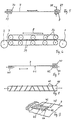
- Fig. 1
- eine Vorderansicht einer Plakataufhängevorrichtung;
- Fig. 2
- einen Schnitt senkrecht zu Transportrichtung und Plakatebene mit zu einer den Plakaträndern zugeordneten Leitkopfführung;
- Fig. 3
- einen Schnitt längs der Linie III - III von Fig. 2;
- Fig. 4
- einen Schnitt senkrecht zu Transportrichtung und Plakatebene mit einer den Plakaträndern zugeordneten Kugelrollenführung;
- Fig. 5
- einen Schnitt senkrecht zu Transportrichtung und Plakatebene mit einem den Plakaträndern zugeordneten Zylinder-Rollenpaar;
- Fig. 6
- einen Schnitt senkrecht zur Plakatebene und parallel zur Transportrichtung durch ein Paar zusammenwirkender Klemmbänder;
- Fig. 7
- einen Schnitt senkrecht zu Plakatfläche und Transportrichtung mit den Plakaträndern zugeordneten Breithaltern;
- Fig. 8
- eine Ausbreitwalze; und
- Fig. 9
- eine Anordnung von zwei Entrollfingern mit dazwischenliegender Leitwalze;
- 1,2 =
- Walze
- 3 =
- Antrieb
- 5 =
- Achse
- 7 =
- Plakatbahn
- 9, 10 =
- Längskante
- 11,12 =
- Haltemittel
- 13,14 =
- Fläche (7)
- 15 =
- Leitkopf (13)
- 16 =
- Leitkopf (14)
- 17 =
- Rundung (15)
- 18 =
- Rundung (16)
- 19 =
- Leitkopfpaar
- 20 =
- Bolzen (15)
- 21 =
- Bolzen (16)
- 22 =
- Schiene
- 23 =
- Längsachse (21)
- 24 =
- Kugellager (21)
- 25 =
- Radpaar
- 26 =
- Achsen (25)
- 27 =
- Schiene (26)
- 28 =
- Peripherie
- 29 =
- Kantenverstärkung
- 30 =
- Kugelrollenschiene
- 31 =
- Kugelrolle
- 32 =
- Hohlraum (30)
- 33 =
- Kugelrollenpaar
- 34 =
- Kugellager
- 35 =
- Puffer
- 36 =
- Rollenpaar
- 37 =
- Rolle
- 38 =
- Preßrichtung
- 39 =
- Bandpaar
- 40 =
- Wendelbreithalter
- 41 =
- Rückseite (7)
- 42 =
- Wulst
- 43 =
- Achse (40)
- 44 =
- Ausbreitwalze
- 45 =
- Entrollfinger
- 46 =
- Leitwalze
- 47 =
- Welle
- 48 =
- Achse
Claims (10)
- Plakataufhängevorrichtung mit zwischen zwei mit Abstand übereinander angeordneten Walzen (1, 2) - unter Längsspannung in Transportrichtung (8) von Walze (1) zu Walze (2) - hin und herfahrbarer Plakatbahn (7), wobei den sich in Transportrichtung (8) erstreckenden seitlichen Längskanten (9, 10) der Plakatbahn (7) im Bereich zwischen den Walzen (1, 2) - von Walze zu Walze reichende - Haltemittel (11, 12) als Seitenführung der Plakatbahn (7) zugeordnet sind, dadurch gekennzeichnet, daß die Haltemittel (11, 12) aus einzelnen, an den Flächen (13, 14) der Plakatbahn (7) mit Abstand voneinander angeordneten Leitköpfen (15, 16) bestehen und daß jeweils einem einer Fläche (13) der Plakatbahn (7) zugewandten Leitkopf (15) ein Leitkopf (16) auf der anderen Plakatbahnfläche (14) unter Bildung eines Leitkopfpaares (19) gegenübersteht.
- Vorrichtung nach Anspruch 1, dadurch gekennzeichnet, daß der einzelne Leitkopf (15, 16) zumindest an seiner der jeweiligen Plakatbahnfläche (13, 14) zugewandten Seite abgerundete (17, 18), vorzugsweise kugelförmig ausgebildet, ist.
- Vorrichtung nach Anspruch 1 oder 2, dadurch gekennzeichnet, daß der einzelne Leitkopf (15, 16) am freien Ende eines annähernd senkrecht zur Plakatbahnfläche (13, 14) stehenden, insbesondere um seine annähernd senkrecht zur Plakatbahnfläche (13, 14) stehende Längsachse (23) drehbar gelagerten, Bolzens (21) vorgesehen ist.
- Vorrichtung nach mindestens einem der Ansprüche 1 bis 5, dadurch gekennzeichnet, daß der einzelne Leitkopf als Rolle bzw. Rad (25, 36) ausgebildet ist, deren Drehachse (26) parallel zur Plakatbahnfläche (13, 14), vorzugsweise zugleich quer zu der Transportrichtung (8), steht.
- Vorrichtung nach mindestens einem der Ansprüche 1 bis 3, dadurch gekennzeichnet, daß der einzelne Leitkopf als - um beliebige Achsen drehbar gelagerte - Kugelrolle (31), vorzugsweise mit an der Fläche (13, 14) der Plakatbahn (7) abrollender Kugel, ausgebildet ist.
- Vorrichtung nach mindestens einem der Ansprüche 1 bis 5, dadurch gekennzeichnet, daß die Plakatbahn (7) eine Kantenverstärkung (29) aufweist und daß der gegenseitige Abstand der Leitköpfe (15, 16) jedes Leitkopfpaars (19) kleiner als die Dicke einer Kantenverstärkung (29) und größer als die Dicke der Plakatbahn (7) ist.
- Vorrichtung nach mindestens einem der Ansprüche 1 bis 6, dadurch gekennzeichnet, daß die Leitköpfe (15, 16) die Plakatbahn (7) angrenzend an deren Längskanten (9, 10) zwischen sich klemmen und dabei - beim Hin- und Herwickeln - an beiden Plakatbahnflächen (13, 14) abrollen.
- Vorrichtung nach mindestens einem der Ansprüche 1 bis 6, dadurch gekennzeichnet, daß jeder der seitlichen Längskanten (9, 10) wenigstens ein angetriebenes Ausbreitmittel jeweils bestehend aus mindestens einem Walzenzapfen bzw. Wendelbreithalter (40), dessen Oberfläche zur jeweiligen Kante hin schraubenförmig divergierende Wülste (42) aufweist, vorzugsweise mit jeweils einem Paar von um ihre Achse (48) drehbaren Entrollfingern (45) mit zwischen den Fingern positionierter Leitwalze (46), zugeordnet ist.
- Vorrichtung nach mindestens einem der Ansprüche 1 bis 8, dadurch gekennzeichnet, daß Leitköpfe (15, 16) und/oder die Haltemittel (11, 12) insgesamt zum Auffangen oder Dämpfen von Windschlägen federnd gelagert sind.
- Vorrichtung nach mindestens einem der Ansprüche 1 bis 9, dadurch gekennzeichnet, daß der gegenseitige Abstand der Leitköpfe (15, 16) des einzelnen Leitkopfpaares (19) einerseits und der gegenseitige Abstand von je zwei sich bezüglich der Plakatbahnbreite - gemessen quer zu der Bahnlängsrichtung - gegenüberliegenden Leitkopfpaaren (19) andererseits so vorgegeben sind, daß die Plakatbahn (7) praktisch ohne statische Querspannung in der Breite fixiert und zugleich in der Längsrichtung (8) fast widerstandslos verschiebbar ist.
Priority Applications (9)
| Application Number | Priority Date | Filing Date | Title |
|---|---|---|---|
| DE50008665T DE50008665D1 (de) | 2000-02-02 | 2000-07-22 | Plakataufhängevorrichtung |
| AT00115826T ATE282876T1 (de) | 2000-02-02 | 2000-07-22 | Plakataufhängevorrichtung |
| EP00115826A EP1122708B1 (de) | 2000-02-02 | 2000-07-22 | Plakataufhängevorrichtung |
| ES00115826T ES2231088T3 (es) | 2000-02-02 | 2000-07-22 | Dispositivo de suspension de carteles. |
| FR0016828A FR2804533B1 (fr) | 2000-02-02 | 2000-12-22 | Dispositif d'affichage a panneau deroulant |
| PL345258A PL198139B1 (pl) | 2000-02-02 | 2001-01-19 | Urządzenie do prezentowania plakatów |
| US09/772,473 US6668473B2 (en) | 2000-02-02 | 2001-01-30 | Device for suspending posters |
| JP2001025714A JP3939501B2 (ja) | 2000-02-02 | 2001-02-01 | ポスタ懸吊装置 |
| BR0100308-9A BR0100308A (pt) | 2000-02-02 | 2001-02-02 | Dispositivo de suspensão de cartaz |
Applications Claiming Priority (5)
| Application Number | Priority Date | Filing Date | Title |
|---|---|---|---|
| DE2000104566 DE10004566A1 (de) | 2000-02-02 | 2000-02-02 | Plakataufhängevorrichtung |
| DE10004566 | 2000-02-02 | ||
| EP00113426 | 2000-06-24 | ||
| EP00113426 | 2000-06-24 | ||
| EP00115826A EP1122708B1 (de) | 2000-02-02 | 2000-07-22 | Plakataufhängevorrichtung |
Publications (3)
| Publication Number | Publication Date |
|---|---|
| EP1122708A2 EP1122708A2 (de) | 2001-08-08 |
| EP1122708A3 EP1122708A3 (de) | 2003-11-12 |
| EP1122708B1 true EP1122708B1 (de) | 2004-11-17 |
Family
ID=27213629
Family Applications (1)
| Application Number | Title | Priority Date | Filing Date |
|---|---|---|---|
| EP00115826A Expired - Lifetime EP1122708B1 (de) | 2000-02-02 | 2000-07-22 | Plakataufhängevorrichtung |
Country Status (9)
| Country | Link |
|---|---|
| US (1) | US6668473B2 (de) |
| EP (1) | EP1122708B1 (de) |
| JP (1) | JP3939501B2 (de) |
| AT (1) | ATE282876T1 (de) |
| BR (1) | BR0100308A (de) |
| DE (1) | DE50008665D1 (de) |
| ES (1) | ES2231088T3 (de) |
| FR (1) | FR2804533B1 (de) |
| PL (1) | PL198139B1 (de) |
Families Citing this family (19)
| Publication number | Priority date | Publication date | Assignee | Title |
|---|---|---|---|---|
| WO2002067233A1 (de) * | 2001-02-16 | 2002-08-29 | Schoening Michael | Plakataufhangevorrichtung |
| FR2837231B1 (fr) * | 2002-03-13 | 2004-09-17 | Beauregard Philippe Blanc | Fixation d'un panneau souple sur une structure avec chariots |
| DE10318770A1 (de) * | 2003-04-25 | 2004-11-11 | Distec Gmbh | Posterwechsler |
| US7155848B2 (en) * | 2003-06-05 | 2007-01-02 | 501413 Ontario Limited | Apparatus for a scrolling sign |
| JP2005249828A (ja) * | 2004-03-01 | 2005-09-15 | Matsushita Electric Ind Co Ltd | 表示装置 |
| GB2415284A (en) * | 2004-06-17 | 2005-12-21 | Astra Signs Ltd | Banner raising and lowering apparatus |
| FR2884025B1 (fr) * | 2005-03-30 | 2007-05-11 | Prismaflex Internat Sa | Dispositif d'affichage a structure modulaire |
| US20070209261A1 (en) * | 2005-12-28 | 2007-09-13 | Rose Displays Ltd. | Roller support arrangement for top and bottom display holder |
| US7743541B2 (en) * | 2007-02-26 | 2010-06-29 | Rose Displays Ltd | Sign holding extrusion arrangement |
| GB201001904D0 (en) * | 2009-05-14 | 2010-03-24 | Giblin Padraig | A structure |
| JP2013094254A (ja) * | 2011-10-28 | 2013-05-20 | Suzuran Kk | X線造影材付吸収材の製造方法及び製造装置 |
| US9428359B2 (en) | 2011-11-30 | 2016-08-30 | Corning Incorporated | Methods and apparatuses for conveying flexible glass substrates |
| KR102339290B1 (ko) * | 2014-12-16 | 2021-12-15 | 삼성디스플레이 주식회사 | 표시 장치 |
| CN109243330B (zh) * | 2018-09-21 | 2021-01-26 | 江苏海事职业技术学院 | 用于学生管理的宣传栏装置 |
| CN110120193B (zh) * | 2019-06-05 | 2021-03-05 | 广州航爵数码科技有限公司 | 一种广告显示装置 |
| US10832599B1 (en) | 2020-01-24 | 2020-11-10 | Innovative Billboards Llc | Scrolling billboard and method of operation |
| US12304773B2 (en) * | 2020-05-15 | 2025-05-20 | The Procter & Gamble Company | Durable transfer roll core and method of making and using the same |
| CN112669734B (zh) * | 2020-12-31 | 2022-06-03 | 聊城职业技术学院 | 一种旅行社专用旅游信息展示装置 |
| PL131253U1 (pl) * | 2023-02-17 | 2024-08-19 | Better Board Spółka Z Ograniczoną Odpowiedzialnością | Tablica informacyjno - reklamowa |
Family Cites Families (14)
| Publication number | Priority date | Publication date | Assignee | Title |
|---|---|---|---|---|
| DE2112786A1 (de) | 1971-03-17 | 1972-09-28 | Erich Weber | Kabel- und Rohrverlegung nach der Schwimmethode |
| US3850358A (en) * | 1971-12-20 | 1974-11-26 | Ibm | Continuous compliant guide for moving web |
| US3927814A (en) * | 1972-11-06 | 1975-12-23 | Riggs & Lombard Inc | Guide for a moving belt |
| US3902648A (en) * | 1973-12-28 | 1975-09-02 | Interlake Inc | Variable width strip conditioner |
| US3915449A (en) * | 1974-11-11 | 1975-10-28 | Xerox Corp | Shiftable pinch roll for magnetic card transport system |
| US4176480A (en) * | 1978-01-09 | 1979-12-04 | Fred F. Solomon | Poster supporting frame |
| JPS6033259B2 (ja) * | 1979-02-02 | 1985-08-01 | ノ−リツ鋼機株式会社 | 長尺写真感光材料の処理機における搬送装置 |
| JPS5627942U (de) * | 1979-08-10 | 1981-03-16 | ||
| IT1186412B (it) | 1985-12-06 | 1987-11-26 | Snam Progetti | Procedimento di varo dalla terraferma di condotte subacquee di grande dimensione,particolarmente per opere di presa |
| SE9203468D0 (sv) * | 1992-11-18 | 1992-11-18 | Gert Johansson | Method and arrangement for framing posters or the like |
| FR2702872B1 (fr) * | 1993-03-17 | 1995-06-16 | Profil Cadres Sarl | Ensemble d'affichage destine notamment a etre monte sur un vehicule utilitaire support et affiche pour un tel ensemble. |
| DE29510670U1 (de) | 1995-07-06 | 1995-09-07 | M & V Reklametechnik Schöning - Krieg, 52525 Heinsberg | Werbevitrine |
| DE19802834C1 (de) | 1998-01-26 | 1999-03-11 | Heinrich Dipl Ing Ursprung | Verfahren zum Verlegen von Unterwasserrohrleitungen |
| FR2799039B1 (fr) | 1999-09-29 | 2002-08-23 | Rigiflex Internat | Dispositif d'affichage par deroulement d'une toile support d'informations |
-
2000
- 2000-07-22 ES ES00115826T patent/ES2231088T3/es not_active Expired - Lifetime
- 2000-07-22 AT AT00115826T patent/ATE282876T1/de not_active IP Right Cessation
- 2000-07-22 DE DE50008665T patent/DE50008665D1/de not_active Expired - Fee Related
- 2000-07-22 EP EP00115826A patent/EP1122708B1/de not_active Expired - Lifetime
- 2000-12-22 FR FR0016828A patent/FR2804533B1/fr not_active Expired - Fee Related
-
2001
- 2001-01-19 PL PL345258A patent/PL198139B1/pl not_active IP Right Cessation
- 2001-01-30 US US09/772,473 patent/US6668473B2/en not_active Expired - Fee Related
- 2001-02-01 JP JP2001025714A patent/JP3939501B2/ja not_active Expired - Fee Related
- 2001-02-02 BR BR0100308-9A patent/BR0100308A/pt active Search and Examination
Also Published As
| Publication number | Publication date |
|---|---|
| PL198139B1 (pl) | 2008-05-30 |
| EP1122708A2 (de) | 2001-08-08 |
| FR2804533B1 (fr) | 2005-02-04 |
| ATE282876T1 (de) | 2004-12-15 |
| EP1122708A3 (de) | 2003-11-12 |
| DE50008665D1 (de) | 2004-12-23 |
| FR2804533A1 (fr) | 2001-08-03 |
| US6668473B2 (en) | 2003-12-30 |
| PL345258A1 (en) | 2001-08-13 |
| US20010010133A1 (en) | 2001-08-02 |
| JP2001242811A (ja) | 2001-09-07 |
| BR0100308A (pt) | 2001-10-09 |
| ES2231088T3 (es) | 2005-05-16 |
| JP3939501B2 (ja) | 2007-07-04 |
Similar Documents
| Publication | Publication Date | Title |
|---|---|---|
| EP1122708B1 (de) | Plakataufhängevorrichtung | |
| DE2341328C3 (de) | Rolltor | |
| EP1034954A2 (de) | Rollo-Sonnenschutz für ein Fahrzeugdach | |
| DE8524022U1 (de) | Abdeckvorrichtung | |
| DE2844432C2 (de) | Kluppenkettenbahn | |
| DE3841139A1 (de) | Sonnenschutzanlage fuer flaechige glasabdeckungen, insbesondere wintergartendaecher | |
| DE2311537A1 (de) | Foerdereinrichtung | |
| EP1736628B1 (de) | Führung für eine Schiebetüre | |
| DE10004566A1 (de) | Plakataufhängevorrichtung | |
| DE4111400C1 (de) | ||
| EP0335177A2 (de) | Vorrichtung zum Abdunkeln von Fenstern | |
| DE4202342C1 (en) | Roller blind for motor car windows - has strip of material wound on rod with cross-strip attached to end of material and can be force down against spiral springs | |
| DE10316785A1 (de) | Rollovorrichtung | |
| EP1360681B1 (de) | Plakataufhangevorrichtung | |
| DE2009206A1 (de) | Personenfördereinrichtung wie Rolltreppe oder Rollsteig | |
| DE3728913A1 (de) | Vorrichtung fuer langbahnige markisen mit schienenfuehrung | |
| EP4074926B1 (de) | Becken-abdeckvorrichtung mit einem zugmotor | |
| DE3820731A1 (de) | Rolloanordnung | |
| DE102016119922B4 (de) | Markise | |
| DE2208298A1 (de) | Vorhang | |
| DE805059C (de) | Vorrichtung zur Fuehrung von Rollvorhangleisten | |
| DE2001783C3 (de) | Zugvorrichtung für einen Faltvorhang | |
| DE698334C (de) | Verdunkelungsvorrichtung fuer Fenster- oder sonstige Lichtoeffnungen | |
| DE10158407A1 (de) | Plakataufhängevorrichtung | |
| DE478424C (de) | Vorrichtung zur Vortaeuschung der AEnderung des Aussehens einer Schauflaeche |
Legal Events
| Date | Code | Title | Description |
|---|---|---|---|
| PUAI | Public reference made under article 153(3) epc to a published international application that has entered the european phase |
Free format text: ORIGINAL CODE: 0009012 |
|
| AK | Designated contracting states |
Kind code of ref document: A2 Designated state(s): AT BE CH CY DE DK ES FI FR GB GR IE IT LI LU MC NL PT SE |
|
| AX | Request for extension of the european patent |
Free format text: AL;LT;LV;MK;RO;SI |
|
| PUAL | Search report despatched |
Free format text: ORIGINAL CODE: 0009013 |
|
| AK | Designated contracting states |
Kind code of ref document: A3 Designated state(s): AT BE CH CY DE DK ES FI FR GB GR IE IT LI LU MC NL PT SE |
|
| AX | Request for extension of the european patent |
Extension state: AL LT LV MK RO SI |
|
| 17P | Request for examination filed |
Effective date: 20031203 |
|
| 17Q | First examination report despatched |
Effective date: 20040130 |
|
| GRAP | Despatch of communication of intention to grant a patent |
Free format text: ORIGINAL CODE: EPIDOSNIGR1 |
|
| AKX | Designation fees paid |
Designated state(s): AT BE CH CY DE DK ES FI FR GB GR IE IT LI LU MC NL PT SE |
|
| GRAS | Grant fee paid |
Free format text: ORIGINAL CODE: EPIDOSNIGR3 |
|
| GRAA | (expected) grant |
Free format text: ORIGINAL CODE: 0009210 |
|
| AK | Designated contracting states |
Kind code of ref document: B1 Designated state(s): AT BE CH CY DE DK ES FI FR GB GR IE IT LI LU MC NL PT SE |
|
| PG25 | Lapsed in a contracting state [announced via postgrant information from national office to epo] |
Ref country code: FI Free format text: LAPSE BECAUSE OF FAILURE TO SUBMIT A TRANSLATION OF THE DESCRIPTION OR TO PAY THE FEE WITHIN THE PRESCRIBED TIME-LIMIT Effective date: 20041117 Ref country code: IE Free format text: LAPSE BECAUSE OF FAILURE TO SUBMIT A TRANSLATION OF THE DESCRIPTION OR TO PAY THE FEE WITHIN THE PRESCRIBED TIME-LIMIT Effective date: 20041117 |
|
| REG | Reference to a national code |
Ref country code: GB Ref legal event code: FG4D Free format text: NOT ENGLISH |
|
| REG | Reference to a national code |
Ref country code: CH Ref legal event code: EP |
|
| RBV | Designated contracting states (corrected) |
Designated state(s): AT BE CH CY DE DK ES FI GB GR IE IT LI LU MC NL PT SE |
|
| REG | Reference to a national code |
Ref country code: IE Ref legal event code: FG4D Free format text: GERMAN |
|
| REF | Corresponds to: |
Ref document number: 50008665 Country of ref document: DE Date of ref document: 20041223 Kind code of ref document: P |
|
| REG | Reference to a national code |
Ref country code: CH Ref legal event code: PFA Owner name: DISTEC GMBH Free format text: DISTEC GMBH#BORSIGSTRASSE 35#52525 HEINSBERG (DE) -TRANSFER TO- DISTEC GMBH#GLADBACHERSTRASSE 23#52525 HEINSBERG (DE) Ref country code: CH Ref legal event code: NV Representative=s name: SCHMAUDER & PARTNER AG PATENTANWALTSBUERO |
|
| PG25 | Lapsed in a contracting state [announced via postgrant information from national office to epo] |
Ref country code: DK Free format text: LAPSE BECAUSE OF FAILURE TO SUBMIT A TRANSLATION OF THE DESCRIPTION OR TO PAY THE FEE WITHIN THE PRESCRIBED TIME-LIMIT Effective date: 20050217 Ref country code: SE Free format text: LAPSE BECAUSE OF FAILURE TO SUBMIT A TRANSLATION OF THE DESCRIPTION OR TO PAY THE FEE WITHIN THE PRESCRIBED TIME-LIMIT Effective date: 20050217 Ref country code: GR Free format text: LAPSE BECAUSE OF FAILURE TO SUBMIT A TRANSLATION OF THE DESCRIPTION OR TO PAY THE FEE WITHIN THE PRESCRIBED TIME-LIMIT Effective date: 20050217 |
|
| GBT | Gb: translation of ep patent filed (gb section 77(6)(a)/1977) |
Effective date: 20050330 |
|
| REG | Reference to a national code |
Ref country code: ES Ref legal event code: FG2A Ref document number: 2231088 Country of ref document: ES Kind code of ref document: T3 |
|
| REG | Reference to a national code |
Ref country code: IE Ref legal event code: FD4D |
|
| PG25 | Lapsed in a contracting state [announced via postgrant information from national office to epo] |
Ref country code: CY Free format text: LAPSE BECAUSE OF FAILURE TO SUBMIT A TRANSLATION OF THE DESCRIPTION OR TO PAY THE FEE WITHIN THE PRESCRIBED TIME-LIMIT Effective date: 20050722 Ref country code: LU Free format text: LAPSE BECAUSE OF NON-PAYMENT OF DUE FEES Effective date: 20050722 |
|
| PG25 | Lapsed in a contracting state [announced via postgrant information from national office to epo] |
Ref country code: MC Free format text: LAPSE BECAUSE OF NON-PAYMENT OF DUE FEES Effective date: 20050731 |
|
| PLBE | No opposition filed within time limit |
Free format text: ORIGINAL CODE: 0009261 |
|
| STAA | Information on the status of an ep patent application or granted ep patent |
Free format text: STATUS: NO OPPOSITION FILED WITHIN TIME LIMIT |
|
| 26N | No opposition filed |
Effective date: 20050818 |
|
| PG25 | Lapsed in a contracting state [announced via postgrant information from national office to epo] |
Ref country code: PT Free format text: LAPSE BECAUSE OF NON-PAYMENT OF DUE FEES Effective date: 20050417 |
|
| REG | Reference to a national code |
Ref country code: CH Ref legal event code: PCAR Free format text: SCHMAUDER & PARTNER AG PATENT- UND MARKENANWAELTE VSP;ZWAENGIWEG 7;8038 ZUERICH (CH) |
|
| PGFP | Annual fee paid to national office [announced via postgrant information from national office to epo] |
Ref country code: ES Payment date: 20090722 Year of fee payment: 10 |
|
| PGFP | Annual fee paid to national office [announced via postgrant information from national office to epo] |
Ref country code: NL Payment date: 20090730 Year of fee payment: 10 Ref country code: DE Payment date: 20090827 Year of fee payment: 10 Ref country code: GB Payment date: 20090722 Year of fee payment: 10 Ref country code: AT Payment date: 20090724 Year of fee payment: 10 Ref country code: CH Payment date: 20090728 Year of fee payment: 10 |
|
| PGFP | Annual fee paid to national office [announced via postgrant information from national office to epo] |
Ref country code: BE Payment date: 20090729 Year of fee payment: 10 |
|
| PGFP | Annual fee paid to national office [announced via postgrant information from national office to epo] |
Ref country code: IT Payment date: 20090723 Year of fee payment: 10 |
|
| BERE | Be: lapsed |
Owner name: *DISTEC G.M.B.H. Effective date: 20100731 |
|
| REG | Reference to a national code |
Ref country code: NL Ref legal event code: V1 Effective date: 20110201 |
|
| REG | Reference to a national code |
Ref country code: CH Ref legal event code: PL |
|
| GBPC | Gb: european patent ceased through non-payment of renewal fee |
Effective date: 20100722 |
|
| PG25 | Lapsed in a contracting state [announced via postgrant information from national office to epo] |
Ref country code: DE Free format text: LAPSE BECAUSE OF NON-PAYMENT OF DUE FEES Effective date: 20110201 Ref country code: LI Free format text: LAPSE BECAUSE OF NON-PAYMENT OF DUE FEES Effective date: 20100731 Ref country code: CH Free format text: LAPSE BECAUSE OF NON-PAYMENT OF DUE FEES Effective date: 20100731 |
|
| REG | Reference to a national code |
Ref country code: DE Ref legal event code: R119 Ref document number: 50008665 Country of ref document: DE Effective date: 20110201 |
|
| PG25 | Lapsed in a contracting state [announced via postgrant information from national office to epo] |
Ref country code: IT Free format text: LAPSE BECAUSE OF NON-PAYMENT OF DUE FEES Effective date: 20100722 Ref country code: NL Free format text: LAPSE BECAUSE OF NON-PAYMENT OF DUE FEES Effective date: 20110201 Ref country code: AT Free format text: LAPSE BECAUSE OF NON-PAYMENT OF DUE FEES Effective date: 20100722 |
|
| PG25 | Lapsed in a contracting state [announced via postgrant information from national office to epo] |
Ref country code: BE Free format text: LAPSE BECAUSE OF NON-PAYMENT OF DUE FEES Effective date: 20100731 |
|
| PG25 | Lapsed in a contracting state [announced via postgrant information from national office to epo] |
Ref country code: GB Free format text: LAPSE BECAUSE OF NON-PAYMENT OF DUE FEES Effective date: 20100722 |
|
| REG | Reference to a national code |
Ref country code: ES Ref legal event code: FD2A Effective date: 20110818 |
|
| PG25 | Lapsed in a contracting state [announced via postgrant information from national office to epo] |
Ref country code: ES Free format text: LAPSE BECAUSE OF NON-PAYMENT OF DUE FEES Effective date: 20100723 |