EP1122389A2 - Anzugseinrichtung zur Bewegung eines Flügels - Google Patents
Anzugseinrichtung zur Bewegung eines Flügels Download PDFInfo
- Publication number
- EP1122389A2 EP1122389A2 EP00127750A EP00127750A EP1122389A2 EP 1122389 A2 EP1122389 A2 EP 1122389A2 EP 00127750 A EP00127750 A EP 00127750A EP 00127750 A EP00127750 A EP 00127750A EP 1122389 A2 EP1122389 A2 EP 1122389A2
- Authority
- EP
- European Patent Office
- Prior art keywords
- tightening
- edge
- wing
- frame
- tightening device
- Prior art date
- Legal status (The legal status is an assumption and is not a legal conclusion. Google has not performed a legal analysis and makes no representation as to the accuracy of the status listed.)
- Granted
Links
- 230000033001 locomotion Effects 0.000 claims description 19
- 238000011161 development Methods 0.000 description 9
- 230000018109 developmental process Effects 0.000 description 9
- 238000010276 construction Methods 0.000 description 3
- 229910052751 metal Inorganic materials 0.000 description 2
- 239000002184 metal Substances 0.000 description 2
- 241001295925 Gegenes Species 0.000 description 1
- 235000003332 Ilex aquifolium Nutrition 0.000 description 1
- 241000209027 Ilex aquifolium Species 0.000 description 1
- 229910052782 aluminium Inorganic materials 0.000 description 1
- XAGFODPZIPBFFR-UHFFFAOYSA-N aluminium Chemical compound [Al] XAGFODPZIPBFFR-UHFFFAOYSA-N 0.000 description 1
- 238000005352 clarification Methods 0.000 description 1
- 238000004519 manufacturing process Methods 0.000 description 1
- 230000000149 penetrating effect Effects 0.000 description 1
- 230000007704 transition Effects 0.000 description 1
- 238000009423 ventilation Methods 0.000 description 1
Images


Classifications
-
- E—FIXED CONSTRUCTIONS
- E05—LOCKS; KEYS; WINDOW OR DOOR FITTINGS; SAFES
- E05C—BOLTS OR FASTENING DEVICES FOR WINGS, SPECIALLY FOR DOORS OR WINDOWS
- E05C9/00—Arrangements of simultaneously actuated bolts or other securing devices at well-separated positions on the same wing
- E05C9/18—Details of fastening means or of fixed retaining means for the ends of bars
- E05C9/1825—Fastening means
- E05C9/1833—Fastening means performing sliding movements
- E05C9/185—Fastening means performing sliding movements parallel with actuating bar
-
- E—FIXED CONSTRUCTIONS
- E05—LOCKS; KEYS; WINDOW OR DOOR FITTINGS; SAFES
- E05B—LOCKS; ACCESSORIES THEREFOR; HANDCUFFS
- E05B17/00—Accessories in connection with locks
- E05B17/0025—Devices for forcing the wing firmly against its seat or to initiate the opening of the wing
- E05B17/0029—Devices for forcing the wing firmly against its seat or to initiate the opening of the wing motor-operated
-
- E—FIXED CONSTRUCTIONS
- E05—LOCKS; KEYS; WINDOW OR DOOR FITTINGS; SAFES
- E05B—LOCKS; ACCESSORIES THEREFOR; HANDCUFFS
- E05B47/00—Operating or controlling locks or other fastening devices by electric or magnetic means
- E05B47/0001—Operating or controlling locks or other fastening devices by electric or magnetic means with electric actuators; Constructional features thereof
- E05B2047/0014—Constructional features of actuators or power transmissions therefor
- E05B2047/0015—Output elements of actuators
- E05B2047/0016—Output elements of actuators with linearly reciprocating motion
-
- E—FIXED CONSTRUCTIONS
- E05—LOCKS; KEYS; WINDOW OR DOOR FITTINGS; SAFES
- E05B—LOCKS; ACCESSORIES THEREFOR; HANDCUFFS
- E05B47/00—Operating or controlling locks or other fastening devices by electric or magnetic means
- E05B47/0001—Operating or controlling locks or other fastening devices by electric or magnetic means with electric actuators; Constructional features thereof
- E05B47/0012—Operating or controlling locks or other fastening devices by electric or magnetic means with electric actuators; Constructional features thereof with rotary electromotors
-
- E—FIXED CONSTRUCTIONS
- E05—LOCKS; KEYS; WINDOW OR DOOR FITTINGS; SAFES
- E05C—BOLTS OR FASTENING DEVICES FOR WINGS, SPECIALLY FOR DOORS OR WINDOWS
- E05C9/00—Arrangements of simultaneously actuated bolts or other securing devices at well-separated positions on the same wing
- E05C9/18—Details of fastening means or of fixed retaining means for the ends of bars
- E05C9/1808—Keepers
-
- E—FIXED CONSTRUCTIONS
- E05—LOCKS; KEYS; WINDOW OR DOOR FITTINGS; SAFES
- E05D—HINGES OR SUSPENSION DEVICES FOR DOORS, WINDOWS OR WINGS
- E05D15/00—Suspension arrangements for wings
- E05D15/48—Suspension arrangements for wings allowing alternative movements
- E05D15/52—Suspension arrangements for wings allowing alternative movements for opening about a vertical as well as a horizontal axis
- E05D15/5205—Suspension arrangements for wings allowing alternative movements for opening about a vertical as well as a horizontal axis with horizontally-extending checks
-
- E—FIXED CONSTRUCTIONS
- E05—LOCKS; KEYS; WINDOW OR DOOR FITTINGS; SAFES
- E05F—DEVICES FOR MOVING WINGS INTO OPEN OR CLOSED POSITION; CHECKS FOR WINGS; WING FITTINGS NOT OTHERWISE PROVIDED FOR, CONCERNED WITH THE FUNCTIONING OF THE WING
- E05F15/00—Power-operated mechanisms for wings
- E05F15/60—Power-operated mechanisms for wings using electrical actuators
- E05F15/603—Power-operated mechanisms for wings using electrical actuators using rotary electromotors
- E05F15/611—Power-operated mechanisms for wings using electrical actuators using rotary electromotors for swinging wings
- E05F15/63—Power-operated mechanisms for wings using electrical actuators using rotary electromotors for swinging wings operated by swinging arms
-
- E—FIXED CONSTRUCTIONS
- E05—LOCKS; KEYS; WINDOW OR DOOR FITTINGS; SAFES
- E05Y—INDEXING SCHEME ASSOCIATED WITH SUBCLASSES E05D AND E05F, RELATING TO CONSTRUCTION ELEMENTS, ELECTRIC CONTROL, POWER SUPPLY, POWER SIGNAL OR TRANSMISSION, USER INTERFACES, MOUNTING OR COUPLING, DETAILS, ACCESSORIES, AUXILIARY OPERATIONS NOT OTHERWISE PROVIDED FOR, APPLICATION THEREOF
- E05Y2900/00—Application of doors, windows, wings or fittings thereof
- E05Y2900/10—Application of doors, windows, wings or fittings thereof for buildings or parts thereof
- E05Y2900/13—Type of wing
- E05Y2900/148—Windows
Definitions
- the invention relates to a tightening device for movement of a wing in the closed position against a frame with a suit edge to be arranged on a first spar, with one swiveling on one in relation to the first spar Tie bar to be arranged and with means for movement of the suit part in the assembled state along its Holms to reach behind the suit edge, the suit edge opposite to the direction of movement of the suit part is inclined.
- the tightening device is the tightening edge on a frame-fixed Lock latch arranged.
- the wing has one fastened on a connecting rod of a connecting rod fitting Locking pin.
- the locking pin comes against the tightening edge and slides along this.
- the locking pin thus serves as a tightening part.
- the locking pin can then be inserted into the Lock latch penetrate and the wing with the frame lock.
- a disadvantage of the known tightening device is that the wing only adjoins the frame Position against the frame. Since the Tightening edge does not hinder the movement of the wing , the length of which is naturally related to the dimensions of the Spar of the frame limited.
- a tightening device is from FR 24 20 634 known without a suit edge, in which a swivel arm on a Forend rail one to lock the wing arranged frame provided drive rod fitting is.
- the faceplate has its longest extension an angled control curve designed as an elongated hole to accommodate a connecting rod connected to a drive rod the link arm controlling the sliding block.
- the sliding block pivots towards Swivel arm. This engages behind the suit part and pulls thus the wing against the frame.
- a disadvantage of the known Suit is that the control of the Movement of the swivel arm is very complex and prone to failure designed.
- a tightening device is known from DE 195 15 708 A1 become, in which the control curve in an intermediate plate is arranged. This allows the Swivel the swivel arm through a large angular range.
- the disadvantage here is the very complex design the control curve and the high number of to be assembled and components to be manufactured. Designed this way this tightening device is also particularly expensive and prone to failure.
- the invention is based on the problem of a tightening device of the type mentioned at the beginning, that they have a movement of the frame with at least little Distance opposite wing allows and is structurally particularly simple.
- the tightening device according to the invention does not require a guide curve with a sliding block sliding along it and is therefore particularly susceptible to interference.
- the tightening device according to the invention is designed in addition, it is particularly simple in construction.
- the invention The tightening device is also particularly compact.
- the tightening device is particularly suitable for use Wings to be tilted and locked by motor Advantage, since there is no hand pressure on the wing be exercised.
- the tightening part can be like the locking pin the known tightening device on the drive rod be attached. This requires the movement of the Part of the suit does not require any additional construction work since the Driving rod when opening, closing and locking the Wing is driven anyway.
- Suit device helps if that A tightening element is provided for arrangement on the frame.
- the movement of the tightening element takes place according to a other advantageous development of the invention particularly simple and requires a particularly small one construction effort when the tightening element is on a fixed Holding part stored and resilient in its protruding position is biased.
- This design can the tightening element when closing the Moving wing of the wing and can therefore this do not jam.
- the range of motion of the tightening element can be adjusted accordingly another advantageous development of the invention Keep it particularly low when the suit part is closer Arrangement towards the frame is provided as one in one frame-fixed locking latch movable locking pin of the Espagnolette fitting.
- the tightening element can be advantageous according to another Further development of the invention is particularly easy to assemble, if a holding part of the tightening element with the The latch is designed as a structural unit.
- the latch and the holding part can, for example, from cast Aluminum component to be made.
- the suit part is according to another advantageous development of the invention is particularly simple, if it is sword-shaped.
- This can Suit part in particular as an inexpensive, angled Metal strips to be made.
- the tightening device according to the invention requires a special one small number to be manufactured and assembled Components if the tightening part as the locking pin of the Espagnolette fitting is formed.
- the tightening device only requires one only tightening part for moving the wing against the Frame and to lock the wing when a tightening edge the latch is aligned with the edge of the suit of the tightening element in the protruding position is arranged, and if one for mounting the locking part provided in the closed position the locking latch outside the range of motion the suit element is arranged.
- the tightening part designed as a locking pin is in accordance with another advantageous development of the invention guided particularly reliably behind the locking edge, if partial areas of the tightening edge of the locking latch and the pulling edge in the protruding position the suit element arranged side by side are. This allows the suit part to move along the spar of the wing first against the edge of the suit of the tightening element. From this suit edge the suit piece slides into the section of the side by side arranged tightening edges up to behind the locking edge. The tightening element can then move in move to its retracted position and lock of the wing.
- a tightening edge of the latch can be according to one avoid other advantageous developments of the invention, when the tightening edge of the tightening element is in the closed position until just before the locking edge of the The latch is movable.
- the intended tightening part is capable of another advantageous development of the invention particularly slide evenly along the edge of the suit if that Tightening part one corresponding to the tightening edge of the tightening element has aligned incline.
- the range of motion of the suit edge in on the wing intended direction can be according to another simply limit advantageous further development of the invention, if a support arm is in the protruding position located tightening element against a stop of the holding part is biased.
- the support arm can also high, when sliding the suit part over the suit edge support generated forces.
- Controlling the movement of the tightening element requires according to another advantageous development of the invention a particularly low effort if the tightening edge the suit element arranged on a suit arm and if the arm is at its free end has a stop for the wing.
- FIG. 1 shows one on a fixed frame 1 pivotable wing 2 with an espagnolette fitting 3 in a side view.
- the wing 2 is located here in a tilted position. With wing 2 it can be, for example, a tilt and turn sash Window or a French window act. Likewise can the wing 2 is a pure tilt wing or a ventilation flap his.
- the frame 1 is horizontal in the area of two Spars 4, 5 shown in section.
- the wing 2 has one in a tilted position against the frame 1 adjacent wing flap 6.
- the espagnolette fitting 3 has a longitudinally movable perpendicular to the plane of the drawing Driving rod 7, which is attached to the wing 2 by one Face plate 8 is covered.
- the faceplate 8 On the Drive rod 7 are the faceplate 8 in the range of Elongated holes 9 penetrating locking pin 10 attached. Only one is shown as an example in the drawing Locking pin 10 shown.
- frame 1 has a latch 11.
- the drive rod 7 can be from one to one horizontal spar 12 of the wing 2 attached and in the Drawing schematically illustrated electromotive Move drive 13.
- the Wing 2 At its bottom is the Wing 2 connected to the frame 1 via a tilting bearing 14.
- the wing 2 In the upper area, the wing 2 is by an extension arm 15 a stay scissors 16 held.
- the stay scissors 16 At a Driving the drive rod 7, the stay scissors 16 is adjusted and the wing 2 pivoted against the frame 1.
- the locking pin moves 10 in the latch 11 and locks the wing 2 in the frame 1.
- FIG. 2a shows the frame 1 from FIG. 1 in a view perpendicular to the latch 11 with an inventive Tightening device 17.
- the wing 2 stands here the frame 1 with a small distance opposite and is in a position immediately before it is locked with the frame 1.
- the wing flap 6 des Wing 2, the locking pin 10 and a tightening part 18 of the The tightening device 17 is shown in section.
- the tightening device 17 has a on the frame 1 swivel-mounted tightening element 19.
- the tightening part 18 is like the locking pin 10 on the arranged on the wing 2, and drive rod 7 shown in Figure 1 attached.
- the tightening element 19 has a tightening arm 20 with a suit edge 21 and is in one protruding, the spar 4 of the frame 1 on which it is attached is, in the direction of the wing 2 outstanding position.
- a spring 22 clamps the tightening element 19 in the drawn position before, in which it is by means of a Support arm 23 is supported on a stop 24.
- the support arm 23 and the arm 20 are made in one piece and have a common bearing 25.
- the latch 11 and a bearing 25 of the tightening element 19 having holding part 26 are designed in one piece and screwed to the frame 1.
- the latch 11 has also a tightening edge 27.
- the locking pin 10 with the latch 11 and the tightening edge 27 form together essentially the tightening device known from practice.
- the suit part 18 is angled Metal strips and sword-shaped and has one corresponding to the tightening edge 21 of the tightening element 19 designed leading edge 28. Furthermore, the pull-on part 18 further away from the wing flap 6 of the wing 2 arranged as the one to be inserted into the latch 11 Locking pin 10.
- the drive rod 7 is the wing 6 finally moved on until his wing flap 6 initially countered one arranged on the free end of the arm 20 Stop 29 arrives.
- the arm 20 is the Wing flap 6 of wing 2 in a retracted, located completely in the area of the spar 4 of the frame 1 Position pivoted. Then the wing overlap 6 of the wing 2 against the frame 1.
- This Tightening position is shown in Figure 2c.
- the suit part 18 has completely slid along the tightening element 19 and is located in one of the tightening elements 19 separate position.
- the wing 2 is from which is on a locking edge 30 of the latch 11 supporting locking pin 10 held.
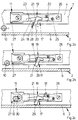
- FIG. 3a shows a tightening device 31 with a tightening part 32 is designed as a locking pin.
- a holding part 33 of a tightening element 34 of the tightening device 31 and a latch 35 are made in one piece.
- the latch 35 has a locking edge 36 and one protruding edge 37.
- the edge 37 is aligned with a tightening edge 38 of the tightening element 34 arranged.
- the suit edges 37, 38 overlap in an area in which they are partially stacked are.
- a tightening arm 40 of the tightening element 34 is in one piece manufactured with a support arm 39 and resilient in Biased towards the wing 2.
- FIG 4a shows a tightening device 42, in which a only the pulling edge 43 is arranged on a pulling element 44 is.
- This tightening device 42 can for example in connection with a tightening device known from practice provided for moving the wing 2 his.
- a known tightening device is, for example in Figures 2a to 2c through the latch 11, the locking pin 10 and the tightening edge 27 shown.
- the wing 2 is usually with several Closing latches 11 shown in FIGS. 2a to 2c locked.
- the tightening element 44 is essentially like that the tightening device 17 from Figure 2a.
- a suit part 45 of the tightening device 42 is as a locking pin trained and can be by means of those shown in Figure 1 Move drive rod 7 to the right until it comes on the tightening edge 43 arrives. On this suit edge 43 slides the suit part 45 and pulls the wing 2 to the frame 1. A middle tightening position is in figure 4b. Finally, the tightening part 45 arrives behind a locking edge 46 of a latch 47 and holds the wing 2 on the frame 1. This tightening position is shown in Figure 4c. At the transition of the Tightening part from that shown in Figure 4b in that shown in 4c Position is the wing of that shown in Figure 2 Pull edge 27 of the latch 11 moves.
Landscapes
- Engineering & Computer Science (AREA)
- Mechanical Engineering (AREA)
- Specific Sealing Or Ventilating Devices For Doors And Windows (AREA)
- Power-Operated Mechanisms For Wings (AREA)
- Mechanical Pencils And Projecting And Retracting Systems Therefor, And Multi-System Writing Instruments (AREA)
- Closing And Opening Devices For Wings, And Checks For Wings (AREA)
- Details Of Spanners, Wrenches, And Screw Drivers And Accessories (AREA)
- Basic Packing Technique (AREA)
Abstract
Description
- Fig.1
- eine schematische Seitenansicht im Teilschnitt eines gegen einen Rahmen schwenkbaren Flügels mit einem Treibstangenbeschlag,
- Fig.2a - 2c
- eine erfindungsgemäße Anzugseinrichtung für den Flügel aus Figur 1 in verschiedenen Anzugsstellungen des Flügels,
- Fig.3a - 3c
- eine weitere Ausführungsform der erfindungsgemäßen Anzugseinrichtung in verschiedenen Anzugsstellungen des Flügels,
- Fig.4a - 4c
- eine weitere Ausführungsform der erfindungsgemäßen Anzugseinrichtung in verschiedenen Anzugsstellungen des Flügels.
Claims (13)
- Anzugseinrichtung zur Bewegung eines Flügels in Schließstellung gegen einen Rahmen mit einer an einem ersten Holm anzuordnenden Anzugskante, mit einem an einem gegenüber dem ersten Holm schwenkbaren Holm anzuordnenden Anzugsteil und mit Mitteln zur Bewegung des Anzugsteils im montierten Zustand längs seines Holms zur Hintergreifung der Anzugskante, wobei die Anzugskante gegenüber der Bewegungsrichtung des Anzugsteils geneigt angeordnet ist, dadurch gekennzeichnet, daß die Anzugskante (21, 38, 43) zumindest teilweise auf einem beweglichen Anzugselement (19, 34, 44) angeordnet ist und daß das Anzugselement (19, 34, 44) in Offenstellung des Flügels (2) in einer hervorstehenden, im montierten Zustand seinen Holm (4) überragenden Stellung und in Schließstellung des Flügels (2) in einer zurückgezogenen, im Bereich seines Holms (4) befindlichen Stellung angeordnet ist.
- Anzugseinrichtung nach Anspruch 1, dadurch gekennzeichnet, daß das Anzugselement (19, 34, 44) zur Anordnung an dem Rahmen (1) vorgesehen ist.
- Anzugseinrichtung nach Anspruch 1 oder 2, dadurch gekennzeichnet, daß das Anzugselement (19, 34, 44) auf einem feststehenden Halteteil (26) gelagert und federelastisch in seine hervorstehende Stellung vorgespannt ist.
- Anzugseinrichtung nach zumindest einem der vorhergehenden Ansprüche, dadurch gekennzeichnet, daß das Anzugsteil (19) zur näheren Anordnung zum Rahmen (1) hin vorgesehen ist als ein in eine rahmenfeste Schließfalle (11) bewegbarer Schließzapfen (10) des Treibstangenbeschlages (3).
- Anzugseinrichtung nach zumindest einem der vorhergehenden Ansprüche, dadurch gekennzeichnet, daß ein Halteteil (26) des Anzugselementes (19, 34, 44) mit der Schließfalle (11, 35, 47) als bauliche Einheit gestaltet ist.
- Anzugseinrichtung nach zumindest einem der vorhergehenden Ansprüche, dadurch gekennzeichnet, daß das Anzugsteil (18) schwertförmig gestaltet ist.
- Anzugseinrichtung nach zumindest einem der vorhergehenden Ansprüche, dadurch gekennzeichnet, daß das Anzugsteil (32, 45) als Schließzapfen des Treibstangenbeschlages (3) ausgebildet ist.
- Anzugseinrichtung nach zumindest einem der vorhergehenden Ansprüche, dadurch gekennzeichnet, daß eine Anzugskante (37) der Schließfalle (35) fluchtend zu der Anzugskante (38) des in der hervorstehenden Stellung befindlichen Anzugselementes (34) angeordnet ist, und daß eine zur Halterung des Anzugsteils (32) in Schließstellung vorgesehene Verriegelungskante (36) der Schließfalle (35) außerhalb des Bewegungsbereichs des Anzugselementes (34) angeordnet ist.
- Anzugseinrichtung nach zumindest einem der vorhergehenden Ansprüche, dadurch gekennzeichnet, daß Teilbereiche der Anzugskante (37) der Schließfalle (35) und der in der hervorstehenden Stellung befindlichen Anzugskante (38) des Anzugselementes (34) nebeneinander angeordnet sind.
- Anzugseinrichtung nach zumindest einem der vorhergehenden Ansprüche, dadurch gekennzeichnet, daß die Anzugskante (43) des Anzugselementes (44) in Schließstellung bis unmittelbar vor die Verriegelungskante (46) der Schließfalle (47) bewegbar ist.
- Anzugseinrichtung nach zumindest einem der vorhergehenden Ansprüche, dadurch gekennzeichnet, daß das Anzugsteil (18) eine entsprechend der Anzugskante (21) des Anzugselementes (19) ausgerichtete Auflaufkante (28) hat.
- Anzugseinrichtung nach zumindest einem der vorhergehenden Ansprüche, dadurch gekennzeichnet, daß ein Abstützarm (23, 39) des in der hervorstehenden Stellung befindlichen Anzugselementes (19, 34, 44) gegen einen Anschlag (24) des Halteteils (26, 33) vorgespannt ist.
- Anzugseinrichtung nach zumindest einem der vorhergehenden Ansprüche, dadurch gekennzeichnet, daß die Anzugskante (21, 38, 43) des Anzugselementes (19, 34, 44) auf einem Anzugsarm (20, 40) angeordnet ist und daß der Anzugsarm (20, 40) an seinem freien Ende einen Anschlag (29, 41) für den Flügel (2) hat.
Applications Claiming Priority (2)
| Application Number | Priority Date | Filing Date | Title |
|---|---|---|---|
| DE10005055 | 2000-02-04 | ||
| DE10005055A DE10005055A1 (de) | 2000-02-04 | 2000-02-04 | Anzugseinrichtung zur Bewegung eines Flügels |
Publications (3)
| Publication Number | Publication Date |
|---|---|
| EP1122389A2 true EP1122389A2 (de) | 2001-08-08 |
| EP1122389A3 EP1122389A3 (de) | 2006-03-15 |
| EP1122389B1 EP1122389B1 (de) | 2009-02-11 |
Family
ID=7629910
Family Applications (1)
| Application Number | Title | Priority Date | Filing Date |
|---|---|---|---|
| EP00127750A Expired - Lifetime EP1122389B1 (de) | 2000-02-04 | 2000-12-19 | Anzugseinrichtung zur Bewegung eines Flügels |
Country Status (5)
| Country | Link |
|---|---|
| EP (1) | EP1122389B1 (de) |
| AT (1) | ATE422594T1 (de) |
| DE (2) | DE10005055A1 (de) |
| DK (1) | DK1122389T3 (de) |
| ES (1) | ES2319499T3 (de) |
Cited By (1)
| Publication number | Priority date | Publication date | Assignee | Title |
|---|---|---|---|---|
| EP2182149A1 (de) | 2008-10-28 | 2010-05-05 | Aug. Winkhaus GmbH & Co. KG | Anzugseinrichtung für einen Treibstangenbeschlag |
Families Citing this family (1)
| Publication number | Priority date | Publication date | Assignee | Title |
|---|---|---|---|---|
| DE102004011880A1 (de) * | 2004-03-11 | 2005-09-29 | Aug. Winkhaus Gmbh & Co. Kg | Schließblech für Fenster oder Fenstertüren |
Citations (2)
| Publication number | Priority date | Publication date | Assignee | Title |
|---|---|---|---|---|
| FR2420634A1 (fr) | 1978-03-23 | 1979-10-19 | Ferco Internal Usine Ferrur Ba | Dispositif pour ferrure pour ouvrants oscillo-battants a poignee unique permettant le rattrapage du baillement de l'ouvrant |
| DE19515708A1 (de) | 1995-04-28 | 1996-10-31 | Winkhaus Fa August | Ausstellvorrichtung für Fenster, Türen oder dergleichen |
Family Cites Families (3)
| Publication number | Priority date | Publication date | Assignee | Title |
|---|---|---|---|---|
| DE3140855A1 (de) * | 1981-10-14 | 1983-04-28 | Geze Gmbh, 7250 Leonberg | Vorrichtung zur betaetigung einer ausstellschere fuer die fluegel von fenstern, tueren oder dergleichen |
| AT386451B (de) * | 1986-06-19 | 1988-08-25 | Frank Gmbh Wilh | Spaltlueftungsvorrichtung fuer einen drehkipp-fluegel eines fensters, einer tuer od. dgl. |
| DE3939043C2 (de) * | 1989-11-25 | 1994-02-24 | Fuhr Carl Gmbh & Co | Beschlag für Fenster, Türen oder dergleichen |
-
2000
- 2000-02-04 DE DE10005055A patent/DE10005055A1/de not_active Withdrawn
- 2000-12-19 EP EP00127750A patent/EP1122389B1/de not_active Expired - Lifetime
- 2000-12-19 AT AT00127750T patent/ATE422594T1/de active
- 2000-12-19 DE DE50015553T patent/DE50015553D1/de not_active Expired - Lifetime
- 2000-12-19 ES ES00127750T patent/ES2319499T3/es not_active Expired - Lifetime
- 2000-12-19 DK DK00127750T patent/DK1122389T3/da active
Patent Citations (2)
| Publication number | Priority date | Publication date | Assignee | Title |
|---|---|---|---|---|
| FR2420634A1 (fr) | 1978-03-23 | 1979-10-19 | Ferco Internal Usine Ferrur Ba | Dispositif pour ferrure pour ouvrants oscillo-battants a poignee unique permettant le rattrapage du baillement de l'ouvrant |
| DE19515708A1 (de) | 1995-04-28 | 1996-10-31 | Winkhaus Fa August | Ausstellvorrichtung für Fenster, Türen oder dergleichen |
Cited By (1)
| Publication number | Priority date | Publication date | Assignee | Title |
|---|---|---|---|---|
| EP2182149A1 (de) | 2008-10-28 | 2010-05-05 | Aug. Winkhaus GmbH & Co. KG | Anzugseinrichtung für einen Treibstangenbeschlag |
Also Published As
| Publication number | Publication date |
|---|---|
| DE50015553D1 (de) | 2009-03-26 |
| EP1122389B1 (de) | 2009-02-11 |
| EP1122389A3 (de) | 2006-03-15 |
| ATE422594T1 (de) | 2009-02-15 |
| ES2319499T3 (es) | 2009-05-08 |
| DK1122389T3 (da) | 2009-05-25 |
| DE10005055A1 (de) | 2001-08-09 |
Similar Documents
| Publication | Publication Date | Title |
|---|---|---|
| EP0249683B2 (de) | Verschlussvorrichtung für die Flügel von Fenstern, Türen od.dgl. | |
| EP0531626B1 (de) | Beschlag für insb. zwangsweise kipp- und parallel abstellbare Flügel | |
| DE19846048C2 (de) | Spaltlüftungsvorrichtung | |
| EP1122389B1 (de) | Anzugseinrichtung zur Bewegung eines Flügels | |
| EP3327236A1 (de) | Vorrichtung zum öffnen und/oder schliessen eines flügels | |
| DE202021102238U1 (de) | Drehkippfenster und Beschlaganordnung | |
| EP0945579A2 (de) | Lüftungseinrichtung | |
| EP1715125A2 (de) | Drehkipp- bzw. Kippdrehfensterbeschlag mit Spaltlüftungsstellung | |
| DE102004060717B4 (de) | Verschluss zur Verriegelung eines Flügels in einem Rahmen eines Fensters | |
| EP1780359A2 (de) | Flügelheber für einen Treibstangenbeschlag | |
| DE1584117A1 (de) | Fluegelfeststeller fuer Fenster,Tueren od. dgl.,insbesondere fuer Kipp-Schwenkfluegel | |
| DE19906071C2 (de) | Drehbegrenzer für Dreh-Schiebe-Fenster | |
| DE1559736A1 (de) | An- und Abdruckvorrichtung fuer die Fluegel von Kipp-Schwenkfenstern,-tueren od.dgl. | |
| DE2929382A1 (de) | Kippriegel-verschlussbeschlag fuer kipp-schwenk-fenster, -tueren o.dgl. | |
| DE2729394A1 (de) | Verriegelungseinrichtung fuer fenster, tueren o.dgl. | |
| EP1503013A2 (de) | Fenster | |
| DE2456057C2 (de) | Kippriegellager für ein Fenster, eine Tür o.dgl. | |
| EP1286014B1 (de) | Fenster oder Fenstertür mit Hilfe der Glasscheibe verriegelt | |
| DE7707617U1 (de) | Urch das fensterverschlussgetriebe betaetigte feststellvorrichtung fuer den fluegel von fenstern, tueren oder dergleichen in einer spaltoffenen lueftungsstellung | |
| DE1584084A1 (de) | Ausstellvorrichtung fuer Drehkippfenster | |
| DE3905995C2 (de) | ||
| EP4230828A1 (de) | Treibstangenbeschlag mit mehreren verschlüssen | |
| DE2059185A1 (de) | Treibstangenverschluss fuer Tueren,Fenster od.dgl. | |
| EP4056797A1 (de) | Treibstangenbeschlag für einen gegen einen rahmen schwenkbaren flügel | |
| EP4105416A1 (de) | Feststellvorrichtung für beidseitig angeschlagene tür |
Legal Events
| Date | Code | Title | Description |
|---|---|---|---|
| PUAI | Public reference made under article 153(3) epc to a published international application that has entered the european phase |
Free format text: ORIGINAL CODE: 0009012 |
|
| AK | Designated contracting states |
Kind code of ref document: A2 Designated state(s): AT BE CH CY DE DK ES FI FR GB GR IE IT LI LU MC NL PT SE TR |
|
| AX | Request for extension of the european patent |
Free format text: AL;LT;LV;MK;RO;SI |
|
| PUAL | Search report despatched |
Free format text: ORIGINAL CODE: 0009013 |
|
| AK | Designated contracting states |
Kind code of ref document: A3 Designated state(s): AT BE CH CY DE DK ES FI FR GB GR IE IT LI LU MC NL PT SE TR |
|
| AX | Request for extension of the european patent |
Extension state: AL LT LV MK RO SI |
|
| 17P | Request for examination filed |
Effective date: 20060712 |
|
| AKX | Designation fees paid |
Designated state(s): AT BE CH CY DE DK ES FI FR GB GR IE IT LI LU MC NL PT SE TR |
|
| 17Q | First examination report despatched |
Effective date: 20070711 |
|
| GRAP | Despatch of communication of intention to grant a patent |
Free format text: ORIGINAL CODE: EPIDOSNIGR1 |
|
| GRAS | Grant fee paid |
Free format text: ORIGINAL CODE: EPIDOSNIGR3 |
|
| GRAA | (expected) grant |
Free format text: ORIGINAL CODE: 0009210 |
|
| AK | Designated contracting states |
Kind code of ref document: B1 Designated state(s): AT BE CH CY DE DK ES FI FR GB GR IE IT LI LU MC NL PT SE TR |
|
| REG | Reference to a national code |
Ref country code: GB Ref legal event code: FG4D Free format text: NOT ENGLISH |
|
| REG | Reference to a national code |
Ref country code: CH Ref legal event code: EP |
|
| REG | Reference to a national code |
Ref country code: IE Ref legal event code: FG4D Free format text: LANGUAGE OF EP DOCUMENT: GERMAN |
|
| REF | Corresponds to: |
Ref document number: 50015553 Country of ref document: DE Date of ref document: 20090326 Kind code of ref document: P |
|
| REG | Reference to a national code |
Ref country code: ES Ref legal event code: FG2A Ref document number: 2319499 Country of ref document: ES Kind code of ref document: T3 |
|
| REG | Reference to a national code |
Ref country code: DK Ref legal event code: T3 |
|
| PG25 | Lapsed in a contracting state [announced via postgrant information from national office to epo] |
Ref country code: FI Free format text: LAPSE BECAUSE OF FAILURE TO SUBMIT A TRANSLATION OF THE DESCRIPTION OR TO PAY THE FEE WITHIN THE PRESCRIBED TIME-LIMIT Effective date: 20090211 |
|
| PG25 | Lapsed in a contracting state [announced via postgrant information from national office to epo] |
Ref country code: SE Free format text: LAPSE BECAUSE OF FAILURE TO SUBMIT A TRANSLATION OF THE DESCRIPTION OR TO PAY THE FEE WITHIN THE PRESCRIBED TIME-LIMIT Effective date: 20090511 |
|
| REG | Reference to a national code |
Ref country code: IE Ref legal event code: FD4D |
|
| PG25 | Lapsed in a contracting state [announced via postgrant information from national office to epo] |
Ref country code: PT Free format text: LAPSE BECAUSE OF FAILURE TO SUBMIT A TRANSLATION OF THE DESCRIPTION OR TO PAY THE FEE WITHIN THE PRESCRIBED TIME-LIMIT Effective date: 20090713 Ref country code: IE Free format text: LAPSE BECAUSE OF FAILURE TO SUBMIT A TRANSLATION OF THE DESCRIPTION OR TO PAY THE FEE WITHIN THE PRESCRIBED TIME-LIMIT Effective date: 20090211 |
|
| PLBE | No opposition filed within time limit |
Free format text: ORIGINAL CODE: 0009261 |
|
| STAA | Information on the status of an ep patent application or granted ep patent |
Free format text: STATUS: NO OPPOSITION FILED WITHIN TIME LIMIT |
|
| 26N | No opposition filed |
Effective date: 20091112 |
|
| PGFP | Annual fee paid to national office [announced via postgrant information from national office to epo] |
Ref country code: DK Payment date: 20091229 Year of fee payment: 10 |
|
| PGFP | Annual fee paid to national office [announced via postgrant information from national office to epo] |
Ref country code: NL Payment date: 20091224 Year of fee payment: 10 |
|
| BERE | Be: lapsed |
Owner name: AUG. WINKHAUS G.M.B.H. & CO. KG Effective date: 20091231 |
|
| PG25 | Lapsed in a contracting state [announced via postgrant information from national office to epo] |
Ref country code: MC Free format text: LAPSE BECAUSE OF NON-PAYMENT OF DUE FEES Effective date: 20100701 |
|
| REG | Reference to a national code |
Ref country code: CH Ref legal event code: PL |
|
| GBPC | Gb: european patent ceased through non-payment of renewal fee |
Effective date: 20091219 |
|
| PG25 | Lapsed in a contracting state [announced via postgrant information from national office to epo] |
Ref country code: CH Free format text: LAPSE BECAUSE OF NON-PAYMENT OF DUE FEES Effective date: 20091231 Ref country code: BE Free format text: LAPSE BECAUSE OF NON-PAYMENT OF DUE FEES Effective date: 20091231 Ref country code: GR Free format text: LAPSE BECAUSE OF FAILURE TO SUBMIT A TRANSLATION OF THE DESCRIPTION OR TO PAY THE FEE WITHIN THE PRESCRIBED TIME-LIMIT Effective date: 20090512 Ref country code: LI Free format text: LAPSE BECAUSE OF NON-PAYMENT OF DUE FEES Effective date: 20091231 |
|
| PG25 | Lapsed in a contracting state [announced via postgrant information from national office to epo] |
Ref country code: GB Free format text: LAPSE BECAUSE OF NON-PAYMENT OF DUE FEES Effective date: 20091219 |
|
| PGFP | Annual fee paid to national office [announced via postgrant information from national office to epo] |
Ref country code: IT Payment date: 20101217 Year of fee payment: 11 Ref country code: TR Payment date: 20101220 Year of fee payment: 11 |
|
| PG25 | Lapsed in a contracting state [announced via postgrant information from national office to epo] |
Ref country code: LU Free format text: LAPSE BECAUSE OF NON-PAYMENT OF DUE FEES Effective date: 20091219 |
|
| PGFP | Annual fee paid to national office [announced via postgrant information from national office to epo] |
Ref country code: ES Payment date: 20101221 Year of fee payment: 11 |
|
| REG | Reference to a national code |
Ref country code: NL Ref legal event code: V1 Effective date: 20110701 |
|
| REG | Reference to a national code |
Ref country code: DK Ref legal event code: EBP |
|
| PG25 | Lapsed in a contracting state [announced via postgrant information from national office to epo] |
Ref country code: CY Free format text: LAPSE BECAUSE OF FAILURE TO SUBMIT A TRANSLATION OF THE DESCRIPTION OR TO PAY THE FEE WITHIN THE PRESCRIBED TIME-LIMIT Effective date: 20090211 |
|
| PG25 | Lapsed in a contracting state [announced via postgrant information from national office to epo] |
Ref country code: NL Free format text: LAPSE BECAUSE OF NON-PAYMENT OF DUE FEES Effective date: 20110701 |
|
| PGFP | Annual fee paid to national office [announced via postgrant information from national office to epo] |
Ref country code: FR Payment date: 20120102 Year of fee payment: 12 |
|
| REG | Reference to a national code |
Ref country code: FR Ref legal event code: ST Effective date: 20130830 |
|
| REG | Reference to a national code |
Ref country code: ES Ref legal event code: FD2A Effective date: 20131023 |
|
| PG25 | Lapsed in a contracting state [announced via postgrant information from national office to epo] |
Ref country code: TR Free format text: LAPSE BECAUSE OF NON-PAYMENT OF DUE FEES Effective date: 20111219 |
|
| PG25 | Lapsed in a contracting state [announced via postgrant information from national office to epo] |
Ref country code: FR Free format text: LAPSE BECAUSE OF NON-PAYMENT OF DUE FEES Effective date: 20130102 |
|
| PG25 | Lapsed in a contracting state [announced via postgrant information from national office to epo] |
Ref country code: IT Free format text: LAPSE BECAUSE OF NON-PAYMENT OF DUE FEES Effective date: 20121219 |
|
| PGFP | Annual fee paid to national office [announced via postgrant information from national office to epo] |
Ref country code: AT Payment date: 20140107 Year of fee payment: 14 |
|
| PG25 | Lapsed in a contracting state [announced via postgrant information from national office to epo] |
Ref country code: ES Free format text: LAPSE BECAUSE OF NON-PAYMENT OF DUE FEES Effective date: 20111220 |
|
| PGFP | Annual fee paid to national office [announced via postgrant information from national office to epo] |
Ref country code: DE Payment date: 20140228 Year of fee payment: 14 |
|
| REG | Reference to a national code |
Ref country code: DE Ref legal event code: R119 Ref document number: 50015553 Country of ref document: DE |
|
| REG | Reference to a national code |
Ref country code: AT Ref legal event code: MM01 Ref document number: 422594 Country of ref document: AT Kind code of ref document: T Effective date: 20141219 |
|
| PG25 | Lapsed in a contracting state [announced via postgrant information from national office to epo] |
Ref country code: DE Free format text: LAPSE BECAUSE OF NON-PAYMENT OF DUE FEES Effective date: 20150701 |
|
| PG25 | Lapsed in a contracting state [announced via postgrant information from national office to epo] |
Ref country code: AT Free format text: LAPSE BECAUSE OF NON-PAYMENT OF DUE FEES Effective date: 20141219 |