EP1122003A1 - Dispositif de fabrication d'une pièce moulée - Google Patents
Dispositif de fabrication d'une pièce moulée Download PDFInfo
- Publication number
- EP1122003A1 EP1122003A1 EP01100652A EP01100652A EP1122003A1 EP 1122003 A1 EP1122003 A1 EP 1122003A1 EP 01100652 A EP01100652 A EP 01100652A EP 01100652 A EP01100652 A EP 01100652A EP 1122003 A1 EP1122003 A1 EP 1122003A1
- Authority
- EP
- European Patent Office
- Prior art keywords
- upper core
- undercut
- slide
- molded part
- casting
- Prior art date
- Legal status (The legal status is an assumption and is not a legal conclusion. Google has not performed a legal analysis and makes no representation as to the accuracy of the status listed.)
- Withdrawn
Links
- 238000000465 moulding Methods 0.000 title claims description 10
- 238000005266 casting Methods 0.000 claims abstract description 40
- 238000003780 insertion Methods 0.000 claims abstract description 25
- 230000037431 insertion Effects 0.000 claims abstract description 25
- 150000001875 compounds Chemical class 0.000 claims abstract description 14
- 239000007788 liquid Substances 0.000 claims abstract description 7
- XAGFODPZIPBFFR-UHFFFAOYSA-N aluminium Chemical compound [Al] XAGFODPZIPBFFR-UHFFFAOYSA-N 0.000 claims description 8
- 229910052782 aluminium Inorganic materials 0.000 claims description 8
- 238000004519 manufacturing process Methods 0.000 claims description 5
- 230000001154 acute effect Effects 0.000 claims description 2
- 239000000463 material Substances 0.000 description 3
- 230000008901 benefit Effects 0.000 description 2
- 230000008878 coupling Effects 0.000 description 2
- 238000010168 coupling process Methods 0.000 description 2
- 238000005859 coupling reaction Methods 0.000 description 2
- 230000007246 mechanism Effects 0.000 description 2
- 230000035508 accumulation Effects 0.000 description 1
- 238000009825 accumulation Methods 0.000 description 1
- 230000015572 biosynthetic process Effects 0.000 description 1
- 238000010276 construction Methods 0.000 description 1
- 238000011161 development Methods 0.000 description 1
- 230000018109 developmental process Effects 0.000 description 1
- 238000009826 distribution Methods 0.000 description 1
- 238000005553 drilling Methods 0.000 description 1
- 230000002996 emotional effect Effects 0.000 description 1
- 230000000149 penetrating effect Effects 0.000 description 1
- 230000009467 reduction Effects 0.000 description 1
- 230000003716 rejuvenation Effects 0.000 description 1
- 239000011800 void material Substances 0.000 description 1
- 239000013585 weight reducing agent Substances 0.000 description 1
Images
Classifications
-
- B—PERFORMING OPERATIONS; TRANSPORTING
- B22—CASTING; POWDER METALLURGY
- B22C—FOUNDRY MOULDING
- B22C9/00—Moulds or cores; Moulding processes
- B22C9/22—Moulds for peculiarly-shaped castings
- B22C9/28—Moulds for peculiarly-shaped castings for wheels, rolls, or rollers
-
- B—PERFORMING OPERATIONS; TRANSPORTING
- B22—CASTING; POWDER METALLURGY
- B22D—CASTING OF METALS; CASTING OF OTHER SUBSTANCES BY THE SAME PROCESSES OR DEVICES
- B22D11/00—Continuous casting of metals, i.e. casting in indefinite lengths
- B22D11/04—Continuous casting of metals, i.e. casting in indefinite lengths into open-ended moulds
- B22D11/0405—Rotating moulds
Definitions
- the invention relates to a device for casting a molded part according to the preamble of claim 1.
- Such a device can be used in particular for casting aluminum existing moldings such as car rims can be provided.
- These devices have a casting mold, which consists essentially of a Lower core, an upper core and several sliders exist.
- the upper core is viewed from above along an insertion direction moving towards the lower core.
- the sliders are on the side Upper and lower core driven, so that between the sliders, the upper core and a cavity is created in the lower core into which the liquid casting compound, preferably liquid aluminum is poured.
- the molded part corresponding to the shape of the cavity essentially has between the sliders and the upper core side walls and a between the upper core and lower core lying on the front wall Open back.
- the upper core becomes Direction of insertion again moved up and over the rear opening of the Molding removed from this.
- the molded part can be removed after removing the slide detached from the lower core and removed.
- the inner diameter tapers so that the upper core can be detached from the molded part of the molded part to the front wall continuously. Correspondingly rejuvenated the outer diameter of the upper core continuously towards the front end.
- the upper core would protrude outwards on a lateral surface local cross-sectional broadening, so the inside of the Side wall of the molded part have a corresponding recess., Which the Cross-sectional broadening encloses. This would make the upper core of the Molded part held and could therefore no longer be detached from the molded part become.
- Undercut areas can be due to the shape of the molded part to be achieved be required, for example, to perform specific functions of the molded part guarantee. In addition, such undercut areas can also cause considerable Material savings can be achieved. To such undercut areas To work into the molded parts, they would have to be after the casting process can also be edited.
- the invention has for its object a device of the aforementioned Kind in such a way that during the casting process in the respective Molding undercut areas can be generated.
- the device according to the invention has an actuating element which can be displaced in the direction of insertion, to which an undercut slide is coupled via a crossmember such that, by displacing the actuating element, the undercut slide runs in a bore in the upper core which runs at a predetermined angle to the direction of insertion.
- the undercut slide is in a first end position during the casting process lying with its front end laterally over the lateral surface of the Core.
- the front end lies during the removal of the upper core of the undercut slide in a second end position and closes with the
- the outer surface of the upper core is flush or lies behind the outer surface.
- undercut slide By means of the undercut slide according to the invention, predetermined Defining the inside of the molded part creates defined undercut areas become.
- the size and shape of the undercut areas can be determined by a suitable choice of the front end of the undercut slide in a simple manner be specified.
- Several undercut slides can also be particularly advantageous be provided for generating several undercut areas.
- An essential advantage of the device according to the invention is that that the undercut areas are incorporated into the molded part during the casting process can be removed without removing the upper core the interior of the molding would be hindered.
- the undercut slide is above the actuating element Casting process moved to its first end position, in which the front end of the undercut slide protrudes over the outer surface of the upper core. Accordingly, a is on the inside of the molding during the casting process corresponding undercut area generated.
- the undercut slide becomes move into a second end position via the actuating element, so that the front end of the undercut valve no longer has the outer surface protrudes from the upper core.
- the upper core can move from the The molded part can be removed.
- the traverse causes the linear movement of the actuating element in also implemented a linear movement of the undercut slide, wherein the movement of the undercut slide is not parallel to the direction of insertion, in which the actuator is moved, but in a predetermined Angle to this is done.
- This angle depends on the design of the traverse and is preferably in the range between 90 ° and 180 °.
- the undercut slide has a parallel can be moved to the insertion direction movable actuator.
- the actuating element can simply be attached to the movement mechanisms be coupled to move the upper core, which is also in the direction of insertion is moved.
- the movement mechanism for deflecting the background slide can thus be implemented with little construction and cost.
- the invention Device used for manufacturing car rim which preferably consists of Aluminum.
- the undercut areas are preferably in the area the connection of the spokes to the rim base of the car rim.
- undercut areas do not cause any unwanted Accumulations of material arise and thus a void formation largely is avoided, thereby reducing reject rates in the production of Car rims can be significantly reduced.
- the car rim has an im substantially constant wall thickness. This leads to an improved casting behavior and also to an improved distribution of forces over the car rim, so that this also significantly increases the stability of the car rim is increased.
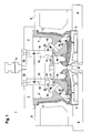
- Figure 1 shows a device 1 for casting molded parts 2.
- these molded parts 2 are formed by car rims and are preferably made of aluminum.
- the device 1 has a lower core 3, an upper core 4 and several Slider 5, which form a mold for the molded part 2 to be created.
- the casting mold has a cavity corresponding to the shape of the molded part 2 in which a liquid casting compound, preferably liquid aluminum is poured.
- the lower core 3 sits on a base plate 6 and forms the lower part the mold.
- the lower core 3 is firmly anchored to the base plate 6.
- the upper core 4 and the slider 5 are slidably arranged.
- the upper core 4 is attached to a holding plate 7.
- the holding plate 7 with the Upper core 4 is arranged displaceably in an insertion direction, the Insertion direction in the present embodiment in the vertical direction runs.
- the upper core 4 is in the vertical direction lowered to the lower core 3.
- several are in the circumferential direction the device 1 side by side slide 5 in the horizontal direction towards the lower core 3 and upper core 4.
- the slider 5 are in sections as shown in Figure 1 on the Upper core 4 and lower core 3 close together, so that the formed from these components Casting mold has a cavity in which the aluminum is poured becomes. This cavity is from interfaces of the upper core 4, the Lower core 3 and the slider 5 are formed.
- the liquid aluminum is in via an insertion opening 8 in the lower core 3 in introduced the cavity of the mold.
- This insertion opening 8 is in the vertical axis of symmetry of the device 1 and the molded part 2.
- the molded part 2 formed by the car rim is essentially rotationally symmetrical trained to the axis of symmetry.
- the device accordingly also has 1 has an essentially rotationally symmetrical structure.
- the substantially cylindrical side wall is located of the molded part 2 between the slider 5 and the lateral surface of the Upper core 4.
- the front wall of the molded part 2 lies between the upper core 4 and lower core 3.
- several spokes are provided, which in the edge area of the Open the front wall into a rim well.
- Molded part 2 removed from the device 1.
- the upper core 4, which protrudes over the open back of the molded part 2 in its interior moved upwards in the vertical direction until the inner sides of the molded part 2 exposed.
- the slides 5 are moved laterally away from the outer walls, so that the molded part 2 can be removed.
- the inside diameter of the molded part 2 tapers essentially continuously towards the front wall.
- Undercut areas 9 are provided in the area of the connection of the rim bed to the spokes the car rim, which is adjacent to the side wall of the molded part 2, several Undercut areas 9 are provided.
- the undercut areas 9 extend refer to the areas of the inside of the side wall of the molded part 2, which are adjacent to the rim base, so that they lead to local cross-sectional widening of the interior of the molded part 2.
- These undercut areas 9 are with several undercut slides during the casting process 10 generated at predetermined intervals in the circumferential direction of the upper core 4 are arranged.
- Each undercut slide 10 is connected to an actuating element via a crossmember 11 coupled.
- the actuating element essentially comprises a column 12, which is attached to the cross member 11, the column 12 preferably on the Traverse 11 is screwed on.
- the longitudinal axis of the cylindrical column 12 runs in the vertical direction.
- the front end of the column 12 is on the Traverse 11 attached.
- the rear end of the column 12 is on a tension plate 13 attached.
- the tension plate 13 is arranged horizontally on the holding plate 7 stored on which the upper core 4 is attached.
- At the top of the pull plate 13 opens a cylinder 14.
- the tension plate 13 By means of the cylinder 14, the tension plate 13 are moved in the vertical direction, which also means that on the tension plate 13 attached columns 12 exert a corresponding vertical movement.
- the undercut slide 10 is guided in a bore 15 of the upper core 4.
- the longitudinal axis of the undercut slide 10 and thus also the longitudinal axis the bore 15 run at an angle ⁇ to the vertical insertion direction, which is in the range between 90 ° and 180 °. In the present embodiment the angle ⁇ is about 135 °.
- the undercut slide 10 is movably coupled to the crossbar 11, the cross member 11 itself is firmly connected to the column 12.
- This coupling causes a movement of the column 12 in the vertical direction implemented via the crossbar 11 so that the undercut slide 10 in the Hole 15 is shifted.
- the undercut slide 10 can move over the deflection the column 12 shifted between a first and second end position become.
- the undercut slide 10 Before the start of the casting process, the undercut slide 10 is in its first End position shifted. In this first end position the front end of the Undercut slide 10 over the outer surface of the upper core 4 and fills the undercut area 9 of the cavity, in which the casting compound is filled will, from.
- This first end position is in Figure 1 for the two undercut slide 10 shown. With one lying in the first end position Undercut slide 10 is the back of the crossbar coupled to this 11 on a right-angled shoulder 16 of the upper core 4.
- the Traverse 11 has a right-angled, adapted to shoulder 16 of upper core 4 Recess 17 on, so that the cross member 11 with this recess 17 sits positively on the shoulder 16 of the upper core 4.
- the casting compound With the undercut slides 10 located in these end positions the casting compound is poured into the cavity.
- the undercut slide 10 lies with its rear part close to the wall of the bore 15. So is ensures that the casting compound does not fall into the Gap between undercut slide 10 and the adjacent part of the upper core 4 can penetrate. Since each undercut slide 10 with its Free end protruding above the upper core 4 into the respective undercut area 9 protrudes, this undercut area 9 becomes during the casting process not filled with casting compound.
- the casting compound solidifies to the molded part 2, whereupon the Upper core 4 by lifting it vertically over the open back the molded part 2 is removed.
- the undercut slides 10 in are removed before the upper core 4 is removed shifted their second end position.
- the tension plate 13 with the Columns 12 shifted upwards in the vertical direction.
- the directions of movement the columns 12 are identified in FIG. 1 by the first arrows 18.
- the crossbeams 11 coupled to the columns 12 are inclined upwards emotional.
- the directions of movement of the trusses 11 are with second arrows 19 marked.
- the rear step slider 10 in the bores 15 in the longitudinal direction into the interior of the Upper core 4 shifted.
- the directions of movement of the undercut slide 10 are identified in FIG. 1 by third arrows 20.
- Each undercut slide 10 is so long inside the upper core 4th moved until it is in its second end position.
- In this second End position is the front end of the undercut slide 10 behind the Shell surface of the upper core 4.
- Figure 1 is the outer edge 21 of the front end of an undercut slide 10 located in the second end position marked with a dashed line.
- An undercut slide 10 in the second end position does not stand more about the outside of the upper core 4, so that the respective undercut area 9 remains free.
- the upper core 4 of the molded part 2 can easily be lifted off.
- the undercut slide 10 has a guide element for coupling to the cross member 11 22, which engages in a guide groove 23 of the crossmember 11.
- the longitudinal axis of the guide groove 23 in the crossmember 11 runs in an acute manner Angle ⁇ to the vertical direction of insertion, in which the column 12 is moved.
- the angle ⁇ is preferably approximately 45 °.
- the longitudinal axis of the guide groove 23 extends perpendicular to the longitudinal axis the traverse 11. The vertical movement of the column 12 becomes the guide element 22 moves along the guide groove 23.
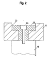
- FIG. 2 shows the structure of the guide element 22 and the guide groove 23.
- the guide element 22 has a T-shaped cross section and is on a surface segment of the undercut slide 10 is screwed on.
- the cross section the guide groove 23 in the cross member 11 is also T-shaped and adapted to the cross section of the guide element 22.
- the guide element is used to couple the undercut slide 10 to the crossmember 11 22 inserted from above into the T-shaped guide groove 23.
- the undercut slide 10 is guided from below to the crossbar 11, so that the surface segment of the undercut slide 10 at the bottom of the Guide groove 23 abuts. Then a screw 24 is inserted into the guide element 22 axially penetrating bore 15 is inserted and on the undercut slide 10 screwed tight. In this way, the undercut slide 10 secured against detachment from the crossmember 11. The screw 24 will tightened only so that the guide element 22 in the guide groove 23 can be moved.
Landscapes
- Engineering & Computer Science (AREA)
- Mechanical Engineering (AREA)
- Moulds For Moulding Plastics Or The Like (AREA)
- Molds, Cores, And Manufacturing Methods Thereof (AREA)
Applications Claiming Priority (2)
| Application Number | Priority Date | Filing Date | Title |
|---|---|---|---|
| DE10004714 | 2000-02-03 | ||
| DE10004714A DE10004714C2 (de) | 2000-02-03 | 2000-02-03 | Vorrichtung zum Gießen eines Formteils |
Publications (1)
| Publication Number | Publication Date |
|---|---|
| EP1122003A1 true EP1122003A1 (fr) | 2001-08-08 |
Family
ID=7629686
Family Applications (1)
| Application Number | Title | Priority Date | Filing Date |
|---|---|---|---|
| EP01100652A Withdrawn EP1122003A1 (fr) | 2000-02-03 | 2001-01-11 | Dispositif de fabrication d'une pièce moulée |
Country Status (6)
| Country | Link |
|---|---|
| US (1) | US6431254B2 (fr) |
| EP (1) | EP1122003A1 (fr) |
| BR (2) | BR0100248A (fr) |
| DE (1) | DE10004714C2 (fr) |
| HU (1) | HU222466B1 (fr) |
| PL (1) | PL345177A1 (fr) |
Families Citing this family (20)
| Publication number | Priority date | Publication date | Assignee | Title |
|---|---|---|---|---|
| EP1189765B1 (fr) * | 1999-06-11 | 2003-04-09 | Dr.Ing. h.c.F. Porsche Aktiengesellschaft | Roue pour vehicule |
| ITPD20010208A1 (it) * | 2001-08-28 | 2003-02-28 | Bbs Riva Spa | Struttura di stampo particolarmente per cerchi di veicoli stradali |
| DE10151037A1 (de) * | 2001-10-16 | 2003-05-08 | Karl Walter Formen Fa | Vorrichtung zum Gießen von Formteilen |
| DE50214427D1 (de) | 2002-01-17 | 2010-06-24 | Siemens Ag | Gegossene Turbinenleitschaufel mit Hakensockel |
| US20050098295A1 (en) * | 2002-09-26 | 2005-05-12 | Dubay Richard L. | Universal slide assembly for molding and casting systems |
| US7600445B2 (en) * | 2003-12-09 | 2009-10-13 | Dubay Richard L | Universal slide assembly for molding and casting system |
| DE102006025830B4 (de) * | 2006-06-02 | 2008-02-14 | Raskopf GmbH Sauerländer Werkzeugfabrik | Kokille |
| US20080041552A1 (en) * | 2006-08-18 | 2008-02-21 | Dubay Richard L | Single-piece cooling blocks for casting and molding |
| US7637305B2 (en) | 2006-09-07 | 2009-12-29 | Dubay Richard L | Two-stage snap cam system for casting and molding |
| US7631851B2 (en) * | 2007-03-02 | 2009-12-15 | Dubay Richard L | High volume vacuum/vent block for molding and casting systems |
| US8424587B1 (en) | 2012-06-05 | 2013-04-23 | Richard L. Dubay | Vacuum/vent block having non-uniform purge passage |
| US9676027B2 (en) * | 2014-12-01 | 2017-06-13 | GM Global Technology Operations LLC | Undercut die casting and injection molding systems and methods |
| CN104827011A (zh) * | 2015-02-18 | 2015-08-12 | 中信戴卡股份有限公司 | 一种铝合金车轮预成型壳和铝合金车轮的低压铸造方法 |
| WO2016196995A1 (fr) | 2015-06-04 | 2016-12-08 | Nike Innovate C.V. | Appareil de moulage, système de moulage, et procédé de moulage d'un composant de semelle d'article chaussant |
| DE102015220980A1 (de) * | 2015-10-27 | 2017-04-27 | Zf Friedrichshafen Ag | Gussform mit mehrteiligem Schieber zur Herstellung metallischer Gussbauteile, damit ausführbares Gießverfahren und hiermit hergestellter Planetenradträger |
| DE102016104019B3 (de) | 2016-03-06 | 2017-03-30 | Argirov ARCONTEC GmbH | Vorrichtung zur Herstellung von Gussteilen, wie Aluminiumguss, im Druckgießverfahren oder Niederdruckgießverfahren |
| WO2018044760A1 (fr) * | 2016-09-01 | 2018-03-08 | American Axle & Manufacturing, Inc. | Appareil de moule ayant un premier tiroir qui déplace un second tiroir |
| CN110202098A (zh) * | 2019-05-29 | 2019-09-06 | 秦皇岛兴龙轮毂有限公司 | 一种轮辐侧壁凹槽结构的铝合金轮毂铸造成形方法 |
| DE102020106059A1 (de) | 2020-03-06 | 2021-09-09 | Bayerische Motoren Werke Aktiengesellschaft | Verfahren zum Herstellen eines Gussbauteils sowie Gießstation |
| CN112122586A (zh) * | 2020-10-30 | 2020-12-25 | 佛山市南海奔达模具有限公司 | 压实机构及所应用的轮毂铸造模具系统 |
Citations (3)
| Publication number | Priority date | Publication date | Assignee | Title |
|---|---|---|---|---|
| EP0423447A2 (fr) * | 1989-08-24 | 1991-04-24 | TVA HOLDING S.p.A. | Procédé et appareil pour la coulée sous pression contrôlée de metaux liquides, notamment d'alliages de métal léger d'aluminium et de magnésium |
| US5415464A (en) * | 1991-11-29 | 1995-05-16 | Alloy Wheels International Ltd. | Cast vehicle wheels |
| US5427171A (en) * | 1993-11-30 | 1995-06-27 | Hayes Wheels International, Inc. | Method and apparatus for casting vehicle wheels having lightener pockets |
Family Cites Families (8)
| Publication number | Priority date | Publication date | Assignee | Title |
|---|---|---|---|---|
| DE3934952A1 (de) | 1989-10-20 | 1991-04-25 | Messerschmitt Boelkow Blohm | Ueberwachungsvorrichtung fuer ein verbindungselement |
| WO1996027467A1 (fr) * | 1995-03-06 | 1996-09-12 | Asahi Tec Corporation | Dispositif de moulage sous pression pour les roues automobiles |
| US5896912A (en) * | 1995-04-27 | 1999-04-27 | Hayes Wheels International, Inc. | Method and apparatus for casting a vehicle wheel in a pressurized mold |
| EP0785038B1 (fr) * | 1996-01-12 | 2002-10-09 | Topy Kogyo Kabushiki Kaisha | Procédé et dispositif pour couler une roue en alliage léger |
| US5865241A (en) * | 1997-04-09 | 1999-02-02 | Exco Technologies Limited | Die casting machine with precisely positionable obliquely moving die core pieces |
| WO1998047722A1 (fr) * | 1997-04-21 | 1998-10-29 | Hayes Lemmerz International, Inc. | Roue moulee comportant des evidements circonferentiels peu profonds |
| US6186218B1 (en) * | 1998-03-17 | 2001-02-13 | Hayes Lemmerz International, Inc. | Modular wheel mold |
| DE19815418C2 (de) * | 1998-04-06 | 2001-10-18 | Wfv Werkzeug Formen Und Vorric | Werkzeug |
-
2000
- 2000-02-03 DE DE10004714A patent/DE10004714C2/de not_active Expired - Fee Related
-
2001
- 2001-01-11 EP EP01100652A patent/EP1122003A1/fr not_active Withdrawn
- 2001-01-17 PL PL01345177A patent/PL345177A1/xx not_active Application Discontinuation
- 2001-01-31 HU HU0100498A patent/HU222466B1/hu not_active IP Right Cessation
- 2001-02-01 BR BR0100248-1A patent/BR0100248A/pt not_active Application Discontinuation
- 2001-02-02 BR BR0100312-7A patent/BR0100312A/pt not_active Application Discontinuation
- 2001-02-05 US US09/775,828 patent/US6431254B2/en not_active Expired - Fee Related
Patent Citations (3)
| Publication number | Priority date | Publication date | Assignee | Title |
|---|---|---|---|---|
| EP0423447A2 (fr) * | 1989-08-24 | 1991-04-24 | TVA HOLDING S.p.A. | Procédé et appareil pour la coulée sous pression contrôlée de metaux liquides, notamment d'alliages de métal léger d'aluminium et de magnésium |
| US5415464A (en) * | 1991-11-29 | 1995-05-16 | Alloy Wheels International Ltd. | Cast vehicle wheels |
| US5427171A (en) * | 1993-11-30 | 1995-06-27 | Hayes Wheels International, Inc. | Method and apparatus for casting vehicle wheels having lightener pockets |
Also Published As
| Publication number | Publication date |
|---|---|
| HUP0100498A2 (hu) | 2001-11-28 |
| DE10004714A1 (de) | 2001-08-16 |
| HU222466B1 (hu) | 2003-07-28 |
| DE10004714C2 (de) | 2002-03-14 |
| HU0100498D0 (en) | 2001-04-28 |
| BR0100312A (pt) | 2001-09-11 |
| BR0100248A (pt) | 2001-10-02 |
| PL345177A1 (en) | 2001-08-13 |
| US20010025699A1 (en) | 2001-10-04 |
| HUP0100498A3 (en) | 2002-01-28 |
| US6431254B2 (en) | 2002-08-13 |
Similar Documents
| Publication | Publication Date | Title |
|---|---|---|
| EP1122003A1 (fr) | Dispositif de fabrication d'une pièce moulée | |
| DE3106952A1 (de) | Metallgussform zum giessen eines hohlkoerpers mit einwaerts geneigter seitenwand | |
| DE2215506C3 (de) | Verriegelungs- und Entriegelungsmechanismus für Druckgieß- und Spritzgießmaschinen | |
| DE102012025117A1 (de) | Gießwerkzeug zur Herstellung eines Bauteils in einem Gasinnendruck-Spritzgussverfahren | |
| DE19507009C2 (de) | Vorrichtung zum Entformen von Spritzgießteilen | |
| EP3678777B1 (fr) | Procédé de fabrication d'une bande de récipients | |
| DE69116439T2 (de) | Verfahren und Vorrichtung zur Herstellung von Produkten aus Polystyrolschaum | |
| DE102005055615B3 (de) | Werkzeug zur Herstellung von Bauteilen durch Spritzguß, Druckguß oder Ablegeverfahren | |
| DE2214646B2 (de) | Kunststoff-Spritzgiefimaschine mit einer Formschließvorrichtung mit rechteckigem Grundkörper | |
| DE20022711U1 (de) | Vorrichtung zum Gießen eines Formteils | |
| DE102009014567B4 (de) | Werkzeug zur Herstellung von Sandkernen oder Gusswerkzeug zur Herstellung von Gussprodukten | |
| EP0896866A2 (fr) | Procédé et dispositif pour la fabrication d'éléments moulés | |
| DE202017101592U1 (de) | Druckgussform | |
| DE19916249A1 (de) | Form zur Verwendung in einem gasunterstützten Spritzgußsystem und einstellbare Überlaufstiftbaugruppe zur Verwendung in diesem | |
| DE19916290A1 (de) | Form zur Verwendung in einem gasunterstützten Spritzgußsystem und Ausstoßstiftuntersystem mit einer Blockierungsstiftbaugruppe zur Verwendung in diesem | |
| DE69314281T2 (de) | Kernführung für giessform und gusstück | |
| DE2040196A1 (de) | Spritzgiessform zum Herstellen von Hohlkoerpern mit einseitiger OEffnung und umlaufender Hinterschneidung | |
| DE202024103987U1 (de) | Schiebereinheit eines Formwerkzeuges | |
| DE2104632C3 (de) | Verfahren und Vorrichtung zur Herstellung von gepreßten Formstücken | |
| DE4234914B4 (de) | Verfahren und Vorrichtung zum Herstellen eines Kunststoff-Spritzgußteils | |
| DE4416182C2 (de) | Spritzgießform zum Herstellen von rohrförmigen Spritzteilen mit Hinterschneidungen | |
| DE1508890C (de) | Spritzgießform zum Herstellen von einseitig offenen Kunststoff artikeln | |
| DE102004007094B3 (de) | Herstellungsverfahren für Metallgußgehäuse | |
| DE102017103152A1 (de) | Gießwerkzeug sowie Verfahren zum Positionieren und Entformen eines Schiebers innerhalb des Gießwerkzeuges | |
| DE2343267A1 (de) | An einem hohlprofil ueber mindestens zwei schrauben befestigtes tuerband |
Legal Events
| Date | Code | Title | Description |
|---|---|---|---|
| PUAI | Public reference made under article 153(3) epc to a published international application that has entered the european phase |
Free format text: ORIGINAL CODE: 0009012 |
|
| AK | Designated contracting states |
Kind code of ref document: A1 Designated state(s): AT BE CH CY DE DK ES FI FR GB GR IE IT LI LU MC NL PT SE TR |
|
| AX | Request for extension of the european patent |
Free format text: AL;LT;LV;MK;RO;SI |
|
| 17P | Request for examination filed |
Effective date: 20011221 |
|
| AKX | Designation fees paid |
Free format text: AT BE CH CY DE DK ES FI FR GB GR IE IT LI LU MC NL PT SE TR |
|
| STAA | Information on the status of an ep patent application or granted ep patent |
Free format text: STATUS: THE APPLICATION IS DEEMED TO BE WITHDRAWN |
|
| 18D | Application deemed to be withdrawn |
Effective date: 20040803 |