EP1120252A2 - Flushing device for a gumming station in a unit for washing, gumming and drying printing plates - Google Patents
Flushing device for a gumming station in a unit for washing, gumming and drying printing plates Download PDFInfo
- Publication number
- EP1120252A2 EP1120252A2 EP01101864A EP01101864A EP1120252A2 EP 1120252 A2 EP1120252 A2 EP 1120252A2 EP 01101864 A EP01101864 A EP 01101864A EP 01101864 A EP01101864 A EP 01101864A EP 1120252 A2 EP1120252 A2 EP 1120252A2
- Authority
- EP
- European Patent Office
- Prior art keywords
- fresh water
- rollers
- liquid
- gumming
- level
- Prior art date
- Legal status (The legal status is an assumption and is not a legal conclusion. Google has not performed a legal analysis and makes no representation as to the accuracy of the status listed.)
- Withdrawn
Links
Images


Classifications
-
- B—PERFORMING OPERATIONS; TRANSPORTING
- B41—PRINTING; LINING MACHINES; TYPEWRITERS; STAMPS
- B41F—PRINTING MACHINES OR PRESSES
- B41F35/00—Cleaning arrangements or devices
- B41F35/001—Devices for cleaning parts removed from the printing machines
-
- B—PERFORMING OPERATIONS; TRANSPORTING
- B41—PRINTING; LINING MACHINES; TYPEWRITERS; STAMPS
- B41P—INDEXING SCHEME RELATING TO PRINTING, LINING MACHINES, TYPEWRITERS, AND TO STAMPS
- B41P2235/00—Cleaning
- B41P2235/10—Cleaning characterised by the methods or devices
- B41P2235/20—Wiping devices
- B41P2235/22—Rollers
-
- B—PERFORMING OPERATIONS; TRANSPORTING
- B41—PRINTING; LINING MACHINES; TYPEWRITERS; STAMPS
- B41P—INDEXING SCHEME RELATING TO PRINTING, LINING MACHINES, TYPEWRITERS, AND TO STAMPS
- B41P2235/00—Cleaning
- B41P2235/10—Cleaning characterised by the methods or devices
- B41P2235/26—Spraying devices
-
- B—PERFORMING OPERATIONS; TRANSPORTING
- B41—PRINTING; LINING MACHINES; TYPEWRITERS; STAMPS
- B41P—INDEXING SCHEME RELATING TO PRINTING, LINING MACHINES, TYPEWRITERS, AND TO STAMPS
- B41P2235/00—Cleaning
- B41P2235/30—Recovering used solvents or residues
Definitions
- the device has an inlet table 1, a washing station, in succession 2, a rinsing station 3, a gumming station 4, a drying device 5 and an outlet table 6.
- a tub 7 for Collecting the washing liquid In the washing station 2 there is a tub 7 for Collecting the washing liquid, a tub 8 for collecting in the rinsing station 3 of the rinse water, in the gumming station 4 a tub 9 for collecting the gum liquid. If necessary, additional washing and rinsing stations can be used be provided.
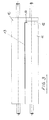
- each station there are at least two pairs of rollers consisting of one Top roller 10 and a bottom roller 11, namely a pair of rollers on the input side the station and another pair of rollers on the exit side of the Station.
- the roller pairs 10, 11 have the task of conveying the printing plates 13, which is why at least one roller can be driven in each pair of rollers.
- she also have the task of guiding the pressure plates 13, which is why the consequence of Nip is in a common flight and the lower roller 11 near her one end has a recess 12 for receiving a folded edge 14 of the pressure plates 13.
- the recesses 12 of the lower rollers are also in one common escape.
- the pair of rollers on the The output side of each station also has the task of the liquid squeeze from the pressure plate.
- the rollers 10, 11 therefore have e.g. one Sheath made of rubber, which is also used for conveying the pressure plates 13 produces the necessary frictional connection with them.
- the top rollers 10 pressed against the lower rollers 11.
- the top rollers 10 be resilient, in such a way that they are raised against spring force can be.
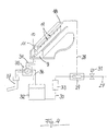
- the last pair of rollers 10, 11 serves in the gumming station 4 for applying a gum liquid to the top of the pressure plate 13.
- the top roller 10 is on the inlet side of the nip Spray tube 18 assigned, which extends parallel to the top roller 10 and from a sequence of nozzles 19 rubber liquid onto a distributor plate 20 sprayed, which rests against the upper roller 10 and the gum liquid as Film 21 distributed on the top roller 10, which it in the nip on the top the pressure plate 13 applies.
- nozzle openings 23 From which air into the outlet side of the nip is blown to prevent gum liquid from flowing through the nip runs through.
- Blowpipes 24 and 25 At a distance from the blowpipe 22 are two more Blowpipes 24 and 25 provided, one above and one below the Pressure plate 13, which has the pressure plate 13 on both sides with nozzle openings Apply cold or warm air to dry them.
- the dried printing plates 13 run on the outlet table 6, from which they can be removed.
- the spray tube and the rollers 10 and 11 must be in front of you every time the system is switched off, otherwise the rubber coating dries, the nozzles 19 of the spray tube clogged and the two rollers 10 and 11 sticks together, which will damage the system when you restart the system Roll cover would lead.
- FIG 4 shows that for the application of the gum liquid and for the subsequent one Rinsing the gum liquid known device.
- the spray pipe 18 is connected via a supply line to an OR valve 29, which on the one hand with the fresh water supply line 27 and on the other hand with a feed line 30 for Gum liquid is connected.
- the OR valve 29 connects the fresh water supply line 27 to the spray tube 18.
- the OR valve 29 connects the Spray tube 18 with a source for the gum liquid, consisting of a Tank 32 and a pump 33, which in the from the tank 32 to the OR valve 29th leading feed line 30 lies.
- the tub 9 has at its bottom an outlet at which a drain line 34 is connected, which leads to a 2/3 way valve 35, which in its one switching position the drain line 34 with a return to the tank 32 Line 36 and in its other switching position, which is shown in Figure 4 is, the drain line 34 connects to a waste water line 37.
- a drain line 34 is connected, which leads to a 2/3 way valve 35, which in its one switching position the drain line 34 with a return to the tank 32 Line 36 and in its other switching position, which is shown in Figure 4 is, the drain line 34 connects to a waste water line 37.
- the pump 33 For rinsing the pump 33 is first switched off and the 2/3 way valve 35 is switched over, so that it connects the drain pipe 34 to the sewage pipe 37, as shown in Figure 4. Then the solenoid valve 31 in the fresh water supply 27 opened and the spray tube 18 and the pair of rollers 10 and 11 rinsed until the gum liquid is washed off the rollers 10, 11. The Mixture of gum liquid and water flows into the waste water line 37.
- the object of the present invention is to show a way in which the sucking back of gum liquid into the fresh water supply line can be prevented without great effort.
- the fresh water supply line no more direct connection to the supply line to the Nozzles through which alternating gum and the essentially Flushing liquid consisting of the fresh water flows.
- the rinsing liquid can consist of pure fresh water. It is also possible, the fresh water additives favoring the rinsing process to add.
- the object of the invention is achieved in a simple and inexpensive manner. It only has to interrupt the fresh water supply and a reservoir be provided for the temporary storage of fresh water.
- the capacity of the storage container can be relatively small because the storage container can be continuously refilled from the fresh water supply.
- To this Purpose can be a level sensor to monitor the highest level and a level sensor to monitor a lower level in the reservoir be provided and these two level sensors can be a solenoid valve Control in the fresh water supply line so that the solenoid valve falls below the predetermined lower level opened and when reaching the predetermined maximum levels is closed.
- shut-off valve in the fresh water supply line a float switch is controlled, which when the highest is reached provided levels the shut-off valve closes and when the The shut-off valve in the fresh water supply line is below the maximum level increasingly opens.
- Another possibility is to use only one in the fresh water supply Shut-off valve, e.g. to provide a solenoid valve and the reservoir for limitation of the water level with an overflow.
- An excess amount of water can flow out through the overflow.
- the water level never reaches the mouth of the fresh water supply.
- the rinsing liquid can be fed from the storage container to the nozzles with a pump become. You could also use the reservoir for the rinsing liquid Arrange high so that the flushing liquid is fed to the nozzles solely by gravity can be. It is particularly preferred for the supply of the gum liquid and to provide the rinsing liquid with a common pump, which optionally with the tank for the gum liquid and with the storage container can be connected for the rinsing liquid. This way it is effective Forced flushing with minimal effort and safe separation of the fresh water network given by the gum liquid.
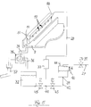
- FIG. 5 shows a schematic representation similar to Figure 4 an embodiment a device according to the invention in a system for which the representations in FIGS. 1 to 3 apply in the same way as examples.
- the device according to the invention differs from the known device in that the fresh water from the fresh water supply line 27 is not direct is fed into the feed line 28 to the spray tube 18, but into a storage container 38, which has an outlet 39 in the floor, at a height above the Bottom has an overflow pipe 40 and a cover with a ventilation opening 41.
- the fresh water supply leads from above into the reservoir 38 and opens at a distance d above the overflow pipe 40.
- the distance d is chosen so that sucking water back into the fresh water supply line 27 among all Circumstances is excluded.
- a line 42 leads from the outlet opening 39 and contains a solenoid valve 43 lies in the feed line 30 leading from the tank 32 to the pump 33, between the mouth 44 of the line 42 into the feed line 30 and the tank 32 is still another solenoid valve 45.
- These two solenoid valves 43 and 45 replace the OR valve 29 of the known device from FIG. 4.
- the device according to the invention agrees with the device in FIG 4 match. Matching parts are therefore with matching reference numbers designated. Instead of the two solenoid valves 43 and 45, one could 2/3 way valve can be used.
- the device according to the invention works as follows:
- the solenoid valves 31 and 43 When gumming, the solenoid valves 31 and 43 are closed, the solenoid valve 45 is open.
- the pump 33 sucks gum liquid from the tank 32 and feeds it into the spray tube 18, from which it emerges through the nozzles 19 and hits the top roller 10.
- the excess of gum liquid is in the Tray 9 collected and leaves through the drain line 34, which is connected to the return line 36 by the 2/3 way valve 35, so that the excess gum liquid is returned to the tank 32.
- the 2/3 way valve 35 is switched over so that the drain line 34 is connected to the sewage line 37.
- the solenoid valve 45 is closed and the solenoid valves 31 and 43 are opened.
- the pump 33 sucks in rinsing liquid, which is essentially fresh water, from the reservoir 38 and feeds it into the spray tube 18 from which it gets onto the rollers 10 and 11 so that they are rinsed off.
- the mixture of rinse water and gum liquid flows through the drain line 34 into the waste water line 37.
- the fresh water supply line 27 fresh water in the reservoir 38 refilled, at most, however the water level reaches the overflow pipe 40.
Abstract
Description
Die Erfindung geht aus von einer Einrichtung zum Spülen einer Gummierstation mit den im Oberbegriff des Anspruchs 1 angegebenen Merkmalen. Ein Teil der Merkmale des Oberbegriffs ist aus der EP 0 703 861 B1 bekannt.
- Figur 1
- zeigt die wesentlichen Elemente einer Anlage zum Waschen, Gummieren und Trocknen von Druckplatten in einer Schrägansicht ohne Gestell und Verkleidung, wie sie sich aus der EP 0 703 861 B1 ergibt,
Figur 2- zeigt als Detail einen Längsschnitt durch ein Walzenpaar in der Gummierstation mit anschließender Trocknungseinrichtung,
- Figur 3
- zeigt die Ansicht des Walzenpaares aus
Figur 2 mit einer im Walzenspalt eingeklemmten Druckplatte, und - Figur 4
- ist eine schematische Darstellung einer bekannten Einrichtung zum Spülen einer solchen Gummierstation.
- Figure 1
- shows the essential elements of a system for washing, gumming and drying printing plates in an oblique view without frame and cladding, as it results from EP 0 703 861 B1,
- Figure 2
- shows as a detail a longitudinal section through a pair of rollers in the gumming station with subsequent drying device,
- Figure 3
- shows the view of the pair of rollers from Figure 2 with a clamped in the nip pressure plate, and
- Figure 4
- is a schematic representation of a known device for flushing such a gumming station.
Die Vorrichtung hat aufeinanderfolgend einen Einlauftisch 1, eine Waschstation
2, eine Spülstation 3, eine Gummierungsstation 4, eine Trocknungseinrichtung 5
und einen Auslauftisch 6. In der Waschstation 2 befindet sich eine Wanne 7 zum
Auffangen der Waschflüssigkeit, in der Spülstation 3 eine Wanne 8 zum Auffangen
des Spülwassers, in der Gummierungsstation 4 eine Wanne 9 zum Auffangen
der Gummierflüssigkeit. Falls erforderlich, können weitere Wasch- und Spülstationen
vorgesehen sein.The device has an inlet table 1, a washing station, in
In jeder Station befinden sich wenigstens zwei Walzenpaare bestehend aus einer
Oberwalze 10 und einer Unterwalze 11, und zwar ein Walzenpaar an der Eingangsseite
der Station und ein weiteres Walzenpaar an der Ausgangsseite der
Station. Die Walzenpaare 10, 11 haben die Aufgabe, die Druckplatten 13 zu fördern,
weshalb wenigstens eine Walze in jedem Walzenpaar antreibbar ist. Sie
haben ferner die Aufgabe, die Druckplatten 13 zu führen, weshalb die Folge der
Walzenspalte in einer gemeinsamen Flucht liegt und die Unterwalze 11 nahe ihrem
einen Ende einen Einstich 12 hat zur Aufnahme eines abgekanteten Randes
14 der Druckplatten 13. Die Einstiche 12 der Unterwalzen liegen ebenfalls in einer
gemeinsamen Flucht. Für die Zwecke der vorliegenden Erfindung kommt es
auf die Führung der Druckplatten 13 durch das Zusammenspiel eines abgekanteten
Randes 14 mit den Einstichen 12 jedoch nicht an. Das Walzenpaar an der
Ausgangsseite einer jeden Station hat darüberhinaus die Aufgabe, die Flüssigkeit
von der Druckplatte abzuquetschen. Die Walzen 10, 11 haben deshalb z.B. einen
Mantel aus Gummi, welcher gleichzeitig den für das Fördern der Druckplatten 13
erforderlichen Reibschluß mit diesen herstellt. Dazu werden die Oberwalzen 10
gegen die Unterwalzen 11 gedrückt. Zu diesem Zweck können die Oberwalzen
10 federnd gelagert sein, und zwar in der Weise, daß sie gegen Federkraft angehoben
werden können. In each station there are at least two pairs of rollers consisting of one
Wie Figur 2 zeigt, dient das letzte Walzenpaar 10, 11 in der Gummierungsstation
4 zum Auftragen einer Gummierflüssigkeit auf die Oberseite der Druckplatte 13.
Zu diesem Zweck ist der Oberwalze 10 auf der Einlaufseite des Walzenspalts ein
Sprührohr 18 zugeordnet, welches sich parallel zur Oberwalze 10 erstreckt und
aus einer Folge von Düsen 19 Gummierflüssigkeit auf ein Verteilerblech 20
sprüht, welches der Oberwalze 10 federnd anliegt und die Gummierflüssigkeit als
Film 21 auf der Oberwalze 10 verteilt, welche sie im Walzenspalt auf die Oberseite
der Druckplatte 13 aufträgt. Auf der Ausgangsseite des Walzenspaltes ist
oberhalb des Walzenspaltes ein parallel zur Oberwalze 10 verlaufendes Blasrohr
22 angeordnet, welches über seine Länge verteilt gegen den Walzenspalt gerichtete
Düsenöffnungen 23 hat, aus denen Luft in die Ausgangsseite des Walzenspaltes
geblasen wird, um zu verhindern, daß Gummierflüssigkeit durch den Walzenspalt
hindurchläuft. In einigem Abstand von dem Blasrohr 22 sind zwei weitere
Blasrohre 24 und 25 vorgesehen, eines oberhalb und eines unterhalb der
Druckplatte 13, welche durch Düsenöffnungen die Druckplatte 13 beidseitig mit
Kaltluft oder mit Warmluft beaufschlagen, um sie zu trocknen.As FIG. 2 shows, the last pair of
Die getrockneten Druckplatten 13 laufen auf den Auslauftisch 6, von welchem sie
abgenommen werden können.The dried
In der Gummierstation müssen das Sprührohr und die Walzen 10 und 11 vor einem
jeden Abschalten der Anlage gespült werden, da sonst die Gummierung
trocknet, die Düsen 19 des Sprührohres verstopft und die beiden Walzen 10 und
11 zusammenklebt, was beim erneuten Start der Anlage zur Beschädigung des
Walzenbelages führen würde.In the gumming station, the spray tube and the
Um das Sprührohr 18 und die Walzen 10 und 11 spülen zu können, ist es bekannt,
nach dem Abschalten der Zufuhr von Gummierflüssigkeit Frischwasser aus
dem Wassernetz in die Zuleitung 28 zum Sprührohr 18 einzuspeisen. Mit dem
Frischwasser werden das Sprührohr 18 und dessen Düsen 19 durchgespült und
von der Gummierflüssigkeit befreit. Durch die Düsen 19 des Sprührohres 18 gelangt
das Wasser auch auf die Oberwalze 10 und verteilt sich durch das Drehen
der beiden Walzen 10 und 11 über beide, so daß die Gummierflüssigkeit von den
beiden beiden Walzen 10 und 11 ebenfalls abgespült wird.In order to be able to rinse the
Figur 4 zeigt die für das Auftragen der Gummierflüssigkeit und für das anschließende
Abspülen der Gummierflüssigkeit bekannte Einrichtung. Das Sprührohr 18
ist über eine Zuleitung mit einem ODER - Ventil 29 verbunden, welches einerseits
mit der Frischwasserzuleitung 27 und andererseits mit einer Speiseleitung 30 für
Gummierflüssigkeit verbunden ist. In der in Figur 4 dargestellten Schaltstellung
verbindet das ODER - Ventil 29 die Frischwasserzuleitung 27 mit dem Sprührohr
18. In der Frischwasserzuleitung 27 liegt ein als Magnetventil ausgebildetes Absperrventil
31. In der anderen Schaltstellung verbindet das ODER - Ventil 29 das
Sprührohr 18 mit einer Quelle für die Gummierflüssigkeit, bestehend aus einem
Tank 32 und einer Pumpe 33, welche in der vom Tank 32 zum ODER - Ventil 29
führenden Speiseleitung 30 liegt.Figure 4 shows that for the application of the gum liquid and for the subsequent one
Rinsing the gum liquid known device. The
Die Wanne 9 hat an ihrem Boden einen Auslaß, an welchen eine Ablaufleitung
34 angeschlossen ist, welche zu einem 2/3 - Wege - Ventil 35 führt, welches in
seiner einen Schaltstellung die Ablaufleitung 34 mit einer zum Tank 32 zurückführenden
Leitung 36 und in seiner anderen Schaltstellung, die in Figur 4 dargestellt
ist, die Ablaufleitung 34 mit einer Abwasserleitung 37 verbindet. Beim Gummieren
ist das Magnetventil 31 in der Frischwasserzuleitung 27 geschlossen und
das ODER - Ventil 29 zur Pumpe 33 hin offen; die Pumpe 33 pumpt Gummierflüssigkeit
aus dem Tank 32 in das Sprührohr 18. Der Überschuß an Gummierflüssigkeit
wird von der Wanne 9 aufgefangen und über die Ablaufleitung 34, das 2/3-Wege
- Ventil 35 und die Leitung 36 zum Tank 32 zurückgeführt. Zum Spülen
wird zuerst die Pumpe 33 abgeschaltet und das 2/3 - Wege - Ventil 35 umgeschaltet,
so daß es die Ablaufleitung 34 mit der Abwasserleitung 37 verbindet,
wie in Figur 4 dargestellt. Dann wird das Magnetventil 31 in der Frischwasserzuleitung
27 geöffnet und das Sprührohr 18 und das Paar Walzen 10 und 11
gespült, bis die Gummierflüssigkeit von den Walzen 10, 11 abgewaschen ist. Das
Gemisch aus Gummierflüssigkeit und Wasser fließt in die Abwasserleitung 37 ab.The
Der Stand der Technik hat den Nachteil, daß bei einem im Wasserleitungsnetz
entstehenden Sog Gummierflüssigkeit in die Frischwasserzuleitung 27 gesaugt
werden kann. Das muß unter allen Umständen verhindert werden. Das Vorschalten
eines Rücklaufverhinderers wird als eine unzureichende Absicherung
angesehen.The prior art has the disadvantage that one in the water supply network
resulting suction gum liquid sucked into the fresh
Der vorliegenden Erfindung liegt die Aufgabe zugrunde, einen Weg aufzuzeigen, wie ohne größeren Aufwand das Rücksaugen von Gummierflüssigkeit in die Frischwasserzuleitung verhindert werden kann.The object of the present invention is to show a way in which the sucking back of gum liquid into the fresh water supply line can be prevented without great effort.
Diese Aufgabe wird gelöst durch eine Einrichtung mit den im Einspruch 1 angegebenen Merkmalen. Vorteilhafte Weiterbildungen der Erfindung sind Gegenstand der Unteransprüche.This object is achieved by a device with those specified in opposition 1 Characteristics. Advantageous developments of the invention are the subject of subclaims.
Infolge der erfindungsgemäßen Ausführung der Spüleinrichtung hat die Frischwasserzuleitung keine unmittelbare Verbindung mehr mit der Zuleitung zu den Düsen, durch welche abwechselnd Gummierflüssigkeit und die im wesentlichen aus dem Frischwasser bestehende Spülflüssigkeit fließen. Bei einem in der Frischwasserzuleitung auftretenden Sog können somit lediglich das in der Frischwasserzuleitung noch enthaltene Frischwasser sowie Luft zurückgesaugt werden, aber keine Gummierflüssigkeit.As a result of the embodiment of the flushing device according to the invention, the fresh water supply line no more direct connection to the supply line to the Nozzles through which alternating gum and the essentially Flushing liquid consisting of the fresh water flows. With one in the Fresh water supply suction can thus only that in the fresh water supply line fresh water and air still contained are sucked back, but no gum liquid.
Die Spülflüssigkeit kann aus reinem Frischwasser bestehen. Es ist aber auch möglich, dem Frischwasser den Spülvorgang begünstigende Zusätze zuzusetzen.The rinsing liquid can consist of pure fresh water. It is also possible, the fresh water additives favoring the rinsing process to add.
Die erfindungsgemäße Aufgabe wird auf einfache und preiswerte Weise gelöst. Es muß lediglich die Frischwasserzuleitung unterbrochen und ein Vorratsbehälter zum Zwischenspeichern von Frischwasser vorgesehen werden. Das Fassungsvermögen des Vorratsbehälters kann verhältnismäßig gering sein, da der Vorratsbehälter aus der Frischwasserzuleitung laufend nachgefüllt werden kann. Zu diesem Zweck kann ein Füllstandssensor zur Überwachung des höchsten Niveaus und ein Füllstandssensor zur Überwachung eines tieferen Niveaus im Vorratsbehälter vorgesehen sein und diese beiden Füllstandssensoren können ein Magnetventil in der Frischwasserzuleitung derart steuern, daß das Magnetventil bei Unterschreiten des vorgegebenen unteren Niveaus geöffnet und beim Erreichen des vorgegebenen Höchstniveaus geschlossen wird. Eine weitere Möglichkeit besteht darin, in der Frischwasserzuleitung ein Absperrventil vorzusehen, welches durch einen Schwimmerschalter gesteuert wird, welcher bei Erreichen des höchsten vorgesehenen Niveaus das Absperrventil schließt und bei einem Absinken des Niveaus unter das Höchstniveau das Absperrventil in der Frischwasserzuleitung zunehmend öffnet.The object of the invention is achieved in a simple and inexpensive manner. It only has to interrupt the fresh water supply and a reservoir be provided for the temporary storage of fresh water. The capacity of the storage container can be relatively small because the storage container can be continuously refilled from the fresh water supply. To this Purpose can be a level sensor to monitor the highest level and a level sensor to monitor a lower level in the reservoir be provided and these two level sensors can be a solenoid valve Control in the fresh water supply line so that the solenoid valve falls below the predetermined lower level opened and when reaching the predetermined maximum levels is closed. Another option is there in the provision of a shut-off valve in the fresh water supply line a float switch is controlled, which when the highest is reached provided levels the shut-off valve closes and when the The shut-off valve in the fresh water supply line is below the maximum level increasingly opens.
Eine andere Möglichkeit besteht darin, in der Frischwasserzuleitung lediglich ein Absperrventil, z.B. ein Magnetventil vorzusehen und den Vorratsbehälter zur Begrenzung des Wasserstandes mit einem Überlauf zu versehen. In diesem Falle genügt es, vor dem Abschalten der Anlage das Magnetventil an die in der Frischwasserzuleitung für eine vorgegebene, nach Erfahrungswerten gewählte oder einstellbare Zeitspanne zu öffnen, so daß Frischwasser in den Vorratsbehälter läuft, welches durch eine Pumpe den Düsen zugeführt wird, um diese und die Walzen in der gewählten Zeitspanne zu spülen und von der Gummierflüssigkeit zu befreien. Eine überschüssige Wassermenge kann über den Überlauf abfließen. Der Wasserspiegel erreicht nie die Mündung der Frischwasserzuleitung.Another possibility is to use only one in the fresh water supply Shut-off valve, e.g. to provide a solenoid valve and the reservoir for limitation of the water level with an overflow. In this case It is sufficient to switch the solenoid valve to that in the fresh water supply before switching off the system for a given or selected based on experience adjustable time span to open, so that fresh water in the reservoir runs, which is fed to the nozzles by a pump, around these and Rinsing in the selected period and rinsing off the gum liquid to free. An excess amount of water can flow out through the overflow. The water level never reaches the mouth of the fresh water supply.
Aus dem Vorratsbehälter kann die Spülflüssigkeit den Düsen mit einer Pumpe zugeführt werden. Man könnte den Vorratsbehälter für die Spülflüssigkeit auch so hoch anordnen, daß die Spülflüssigkeit allein durch Schwerkraft den Düsen zugeführt werden kann. Besonders bevorzugt ist es, für das Zuführen der Gummierflüssigkeit und der Spülflüssigkeit eine gemeinsame Pumpe vorzusehen, welche wahlweise mit dem Tank für die Gummierflüssigkeit und mit dem Vorratsbehälter für die Spülflüssigkeit verbunden werden kann. Auf diese Weise ist eine wirksame Zwangsspülung mit minimalem Aufwand und sicherer Trennung des Frischwassernetzes von der Gummierflüssigkeit gegeben.The rinsing liquid can be fed from the storage container to the nozzles with a pump become. You could also use the reservoir for the rinsing liquid Arrange high so that the flushing liquid is fed to the nozzles solely by gravity can be. It is particularly preferred for the supply of the gum liquid and to provide the rinsing liquid with a common pump, which optionally with the tank for the gum liquid and with the storage container can be connected for the rinsing liquid. This way it is effective Forced flushing with minimal effort and safe separation of the fresh water network given by the gum liquid.
Figur 5 zeigt in einer schematischen Darstellung ähnlich der Figur 4 ein Ausführungsbeispiel
einer erfindungsgemäßen Einrichtung in einer Anlage, für welche
die Darstellungen in den Figuren 1 bis 3 in gleicher Weise beispielhaft zutreffen.
Die erfindungsgemäße Einrichtung unterscheidet sich von der bekannten Einrichtung
darin, daß das Frischwasser aus der Frischwasserzuführleitung 27 nicht direkt
in die Zuleitung 28 zum Sprührohr 18 eingespeist wird, sondern in einen Vorratsbehälter
38, welcher im Boden einen Auslauf 39, in einiger Höhe über dem
Boden ein Überlaufrohr 40 und einen Deckel mit einer Belüftungsöffnung 41 hat.
Die Frischwasserzuleitung führt von oben her in den Vorratsbehälter 38 und mündet
in einem Abstand d oberhalb des Überlaufrohres 40. Der Abstand d ist so gewählt,
daß ein Rücksaugen von Wasser in die Frischwasserzuleitung 27 unter allen
Umständen ausgeschlossen ist. Ein geeigneter Abstand ist d = 50mm.Figure 5 shows a schematic representation similar to Figure 4 an embodiment
a device according to the invention in a system for which
the representations in FIGS. 1 to 3 apply in the same way as examples.
The device according to the invention differs from the known device
in that the fresh water from the fresh
Von der Auslauföffnung 39 führt eine Leitung 42, in welcher ein Magnetventil 43
liegt, in die vom Tank 32 zur Pumpe 33 führende Speiseleitung 30, wobei zwischen
der Einmündung 44 der Leitung 42 in die Speiseleitung 30 und den Tank
32 noch ein weiteres Magnetventil 45 liegt. Diese beiden Magnetventile 43 und
45 ersetzen das ODER - Ventil 29 der bekannten Einrichtung aus Figur 4.A line 42 leads from the
Im übrigen stimmt die erfindungsgemäße Einrichtung mit der Einrichtung in Figur
4 überein. Übereinstimmende Teile sind deshalb mit übereinstimmenden Bezugszahlen
bezeichnet. Anstelle der beiden Magnetventile 43 und 45 könnte auch ein
2/3 - Wege - Ventil eingesetzt werden.Otherwise, the device according to the invention agrees with the device in FIG
4 match. Matching parts are therefore with matching reference numbers
designated. Instead of the two
Die erfindungsgemäße Einrichtung arbeitet folgendermaßen: The device according to the invention works as follows:
Beim Gummieren sind die Magnetventile 31 und 43 geschlossen, das Magnetventil
45 ist geöffnet. Die Pumpe 33 saugt Gummierflüssigkeit aus dem Tank 32
und speist sie in das Sprührohr 18, aus welchem sie durch die Düsen 19 austritt
und auf die Oberwalze 10 trifft. Der Überschuß an Gummierflüssigkeit wird in der
Wanne 9 aufgefangen und verläßt diese durch die Ablaufleitung 34, welche
durch das 2/3 - Wege - Ventil 35 mit der rückführenden Leitung 36 verbunden ist,
so daß die überschüssige Gummierflüssigkeit in den Tank 32 zurückgeführt wird.
Zum Spülen wird das 2/3 - Wege - Ventil 35 umgeschaltet, so daß die Ablaufleitung
34 mit der Abwasserleitung 37 verbunden ist. Das Magnetventil 45 wird geschlossen
und die Magnetventile 31 und 43 werden geöffnet. Die Pumpe 33
saugt Spülflüssigkeit, bei welcher es sich im wesentlichen um Frischwasser handelt,
aus dem Vorratsbehälter 38 ab und speist es in das Sprührohr 18 ein, von
welchem es auf die Walzen 10 und 11 gelangt, so daß diese abgespült werden.
Das Gemisch aus Spülwasser und Gummierflüssigkeit gelangt über die Ablaufleitung
34 in die Abwasserleitung 37. Gleichzeitig wird aus der Frischwasserzuleitung
27 Frischwasser in den Vorratsbehälter 38 nachgefüllt, höchstens jedoch bis
der Wasserstand das Überlaufrohr 40 erreicht. When gumming, the
- 11
- EinlauftischInfeed table
- 22nd
- WaschstationWashing station
- 33rd
- SpülstationRinsing station
- 44th
- GummierungsstationGumming station
- 55
- TrocknungseinrichtungDrying facility
- 66
- AuslauftischOutlet table
- 77
- WanneTub
- 88th
- WanneTub
- 99
- WanneTub
- 1010th
- OberwalzeTop roller
- 1111
- UnterwalzeBottom roller
- 1212th
- Einstichpuncture
- 1313
- DruckplattenPrinting plates
- 1414
- Randedge
- 15 16 17 1815 16 17th 18th
- SprührohrSpray tube
- 1919th
- DüsenNozzles
- 2020th
- VerteilerblechDistributor plate
- 2121
- FilmMovie
- 2222
- BlasrohrBlowpipe
- 2323
- DüsenöffnungenNozzle openings
- 2424th
- BlasrohrBlowpipe
- 2525th
- BlasrohrBlowpipe
- 2626
- FörderrichtungDirection of conveyance
- 2727
- FrischwasserzuleitungFresh water supply
- 2828
- Zuleitung zum SprührohrSupply line to the spray pipe
- 2929
- ODER - VentilOR - valve
- 3030th
- SpeiseleitungFeed line
- 3131
- Absperrventil (Magnetventil)Shut-off valve (solenoid valve)
- 3232
- Tanktank
- 3333
- Pumpepump
- 3434
- AblaufleitungDrain pipe
- 3535
- 2/3 - Wege - Ventil2/3 way valve
- 3636
- rückführende Leitungreturn line
- 3737
- AbwasserleitungSewer pipe
- 3838
- VorratsbehälterStorage container
Claims (8)
(Kennzeichen)
(Mark)
Applications Claiming Priority (2)
| Application Number | Priority Date | Filing Date | Title |
|---|---|---|---|
| DE20001524U | 2000-01-28 | ||
| DE20001524U DE20001524U1 (en) | 2000-01-28 | 2000-01-28 | Device for rinsing a gumming station in a system for washing, gumming and drying printing plates |
Publications (2)
| Publication Number | Publication Date |
|---|---|
| EP1120252A2 true EP1120252A2 (en) | 2001-08-01 |
| EP1120252A3 EP1120252A3 (en) | 2002-09-18 |
Family
ID=7936543
Family Applications (1)
| Application Number | Title | Priority Date | Filing Date |
|---|---|---|---|
| EP01101864A Withdrawn EP1120252A3 (en) | 2000-01-28 | 2001-01-26 | Flushing device for a gumming station in a unit for washing, gumming and drying printing plates |
Country Status (2)
| Country | Link |
|---|---|
| EP (1) | EP1120252A3 (en) |
| DE (1) | DE20001524U1 (en) |
Cited By (2)
| Publication number | Priority date | Publication date | Assignee | Title |
|---|---|---|---|---|
| CN1328069C (en) * | 2001-11-06 | 2007-07-25 | 曼.罗兰.德鲁克马辛伦公司 | Print surface washing and cleaning method and apparatus for printing plate and rubber roller |
| CN105775880A (en) * | 2014-12-24 | 2016-07-20 | 重庆鑫仕达包装设备有限公司 | Compound machine |
Families Citing this family (1)
| Publication number | Priority date | Publication date | Assignee | Title |
|---|---|---|---|---|
| DE102006027768B3 (en) * | 2006-06-16 | 2007-10-11 | Technotrans Ag | Washing bar for applying washing fluid to cleaning element of washing device of impression cylinder of offset printing press has spray pipe pretensioned against impingement surface by means of adjustable spring force |
Citations (3)
| Publication number | Priority date | Publication date | Assignee | Title |
|---|---|---|---|---|
| EP0612618A2 (en) * | 1993-02-25 | 1994-08-31 | DeMoore, Howard W. | Automatic coating circulation and wash-up system for printing presses |
| EP0703861A1 (en) * | 1993-06-18 | 1996-04-03 | Hanosek Christian Peter | Device for washing and drying printing plates |
| GB2310166A (en) * | 1996-02-09 | 1997-08-20 | Elsen Ltd | An apparatus for washing printing plates |
-
2000
- 2000-01-28 DE DE20001524U patent/DE20001524U1/en not_active Expired - Lifetime
-
2001
- 2001-01-26 EP EP01101864A patent/EP1120252A3/en not_active Withdrawn
Patent Citations (3)
| Publication number | Priority date | Publication date | Assignee | Title |
|---|---|---|---|---|
| EP0612618A2 (en) * | 1993-02-25 | 1994-08-31 | DeMoore, Howard W. | Automatic coating circulation and wash-up system for printing presses |
| EP0703861A1 (en) * | 1993-06-18 | 1996-04-03 | Hanosek Christian Peter | Device for washing and drying printing plates |
| GB2310166A (en) * | 1996-02-09 | 1997-08-20 | Elsen Ltd | An apparatus for washing printing plates |
Cited By (3)
| Publication number | Priority date | Publication date | Assignee | Title |
|---|---|---|---|---|
| CN1328069C (en) * | 2001-11-06 | 2007-07-25 | 曼.罗兰.德鲁克马辛伦公司 | Print surface washing and cleaning method and apparatus for printing plate and rubber roller |
| CN105775880A (en) * | 2014-12-24 | 2016-07-20 | 重庆鑫仕达包装设备有限公司 | Compound machine |
| CN105775880B (en) * | 2014-12-24 | 2023-06-23 | 重庆鑫仕达包装设备有限公司 | Composite machine |
Also Published As
| Publication number | Publication date |
|---|---|
| EP1120252A3 (en) | 2002-09-18 |
| DE20001524U1 (en) | 2000-05-04 |
Similar Documents
| Publication | Publication Date | Title |
|---|---|---|
| DE1617959A1 (en) | Method and device for the aseptic removal of liquid from a packaging material in web form | |
| EP1772093A1 (en) | Device for moistening and wringing a mop | |
| DE2745498C3 (en) | Device for controlling a refilling of liquid in a cleaning mixture | |
| DE4132350A1 (en) | SANITARY DEVICE | |
| DE60318708T2 (en) | PORTABLE SURFACE TREATMENT DEVICE | |
| EP1120252A2 (en) | Flushing device for a gumming station in a unit for washing, gumming and drying printing plates | |
| EP1219224B1 (en) | Device for moistening and wringing a mop | |
| EP1198643A1 (en) | Application device | |
| WO2009059779A2 (en) | Cleaning/drying device for cleaning and/or drying upholstery and/or surfaces in a motor vehicle | |
| DE102006033668A1 (en) | Cleaning device for flat surfaces, especially windows, has suction device with part of air blown to dosing device providing pressure medium | |
| DE112006002157T5 (en) | Method and arrangement for improving the usability of a slide-fed curtain coater and reducing the loss of coating materials | |
| DE2753922A1 (en) | DEVICE FOR MAKING A MIXED DRINK FROM SYRUP AND WATER AT ANY TIME | |
| EP1618965A2 (en) | Color change device for applying uniformly along the width a thin liquid film onto a web | |
| DE2417580A1 (en) | METHOD AND DEVICE FOR DIRECTING A JET OF LIQUID, CONTAINING SOLID ABRASION PARTICLES, ON THE SURFACE OF A WORKPIECE | |
| DE1546211B2 (en) | DEVICE FOR DEGREASING STRIP-SHAPED MATERIAL | |
| DE202013102761U1 (en) | Device for surface sizing of a fibrous web | |
| DE102004044041A1 (en) | Device for dehumidifying or moistening a wet mop | |
| DE3515791A1 (en) | Cleaning device | |
| DE1546211C3 (en) | Device for degreasing strip-shaped material | |
| DE1966792C2 (en) | Lifting device for wastewater or the like mixed with thick matter | |
| DE2638978A1 (en) | DEVICE FOR SEPARATING AND REMOVING WASHED-OUT DIRT PARTICLES FROM A WASHING MACHINE FOR RAIL-SHAPED MATERIAL | |
| DE102004058570B3 (en) | Supply device for washing fluid has injector in supply line from collecting container to spray bar and suction inlet of injector receiving return line from other end of bar | |
| DE2204307C3 (en) | Device for continuously adding substances to a stream of water | |
| DE60110607T2 (en) | DEVICE FOR APPLYING A COATING LIQUID TO A PANEL | |
| CH447115A (en) | Continuous filtering device for liquids |
Legal Events
| Date | Code | Title | Description |
|---|---|---|---|
| PUAI | Public reference made under article 153(3) epc to a published international application that has entered the european phase |
Free format text: ORIGINAL CODE: 0009012 |
|
| AK | Designated contracting states |
Kind code of ref document: A2 Designated state(s): AT BE CH CY DE DK ES FI FR GB GR IE IT LI LU MC NL PT SE TR |
|
| AX | Request for extension of the european patent |
Free format text: AL;LT;LV;MK;RO;SI |
|
| PUAL | Search report despatched |
Free format text: ORIGINAL CODE: 0009013 |
|
| AK | Designated contracting states |
Kind code of ref document: A3 Designated state(s): AT BE CH CY DE DK ES FI FR GB GR IE IT LI LU MC NL PT SE TR |
|
| AX | Request for extension of the european patent |
Free format text: AL;LT;LV;MK;RO;SI |
|
| AKX | Designation fees paid | ||
| REG | Reference to a national code |
Ref country code: DE Ref legal event code: 8566 |
|
| STAA | Information on the status of an ep patent application or granted ep patent |
Free format text: STATUS: THE APPLICATION IS DEEMED TO BE WITHDRAWN |
|
| 18D | Application deemed to be withdrawn |
Effective date: 20030319 |