EP1120252A2 - Einrichtung zum Spülen einer Gummierstation in einer Anlage zum Waschen, Gummieren und Trocknen von Druckplatten - Google Patents
Einrichtung zum Spülen einer Gummierstation in einer Anlage zum Waschen, Gummieren und Trocknen von Druckplatten Download PDFInfo
- Publication number
- EP1120252A2 EP1120252A2 EP01101864A EP01101864A EP1120252A2 EP 1120252 A2 EP1120252 A2 EP 1120252A2 EP 01101864 A EP01101864 A EP 01101864A EP 01101864 A EP01101864 A EP 01101864A EP 1120252 A2 EP1120252 A2 EP 1120252A2
- Authority
- EP
- European Patent Office
- Prior art keywords
- rollers
- rinsing liquid
- liquid
- die
- fresh water
- Prior art date
- Legal status (The legal status is an assumption and is not a legal conclusion. Google has not performed a legal analysis and makes no representation as to the accuracy of the status listed.)
- Withdrawn
Links
Images


Classifications
-
- B—PERFORMING OPERATIONS; TRANSPORTING
- B41—PRINTING; LINING MACHINES; TYPEWRITERS; STAMPS
- B41F—PRINTING MACHINES OR PRESSES
- B41F35/00—Cleaning arrangements or devices
- B41F35/001—Devices for cleaning parts removed from the printing machines
-
- B—PERFORMING OPERATIONS; TRANSPORTING
- B41—PRINTING; LINING MACHINES; TYPEWRITERS; STAMPS
- B41P—INDEXING SCHEME RELATING TO PRINTING, LINING MACHINES, TYPEWRITERS, AND TO STAMPS
- B41P2235/00—Cleaning
- B41P2235/10—Cleaning characterised by the methods or devices
- B41P2235/20—Wiping devices
- B41P2235/22—Rollers
-
- B—PERFORMING OPERATIONS; TRANSPORTING
- B41—PRINTING; LINING MACHINES; TYPEWRITERS; STAMPS
- B41P—INDEXING SCHEME RELATING TO PRINTING, LINING MACHINES, TYPEWRITERS, AND TO STAMPS
- B41P2235/00—Cleaning
- B41P2235/10—Cleaning characterised by the methods or devices
- B41P2235/26—Spraying devices
-
- B—PERFORMING OPERATIONS; TRANSPORTING
- B41—PRINTING; LINING MACHINES; TYPEWRITERS; STAMPS
- B41P—INDEXING SCHEME RELATING TO PRINTING, LINING MACHINES, TYPEWRITERS, AND TO STAMPS
- B41P2235/00—Cleaning
- B41P2235/30—Recovering used solvents or residues
Definitions
- the device has an inlet table 1, a washing station, in succession 2, a rinsing station 3, a gumming station 4, a drying device 5 and an outlet table 6.
- a tub 7 for Collecting the washing liquid In the washing station 2 there is a tub 7 for Collecting the washing liquid, a tub 8 for collecting in the rinsing station 3 of the rinse water, in the gumming station 4 a tub 9 for collecting the gum liquid. If necessary, additional washing and rinsing stations can be used be provided.
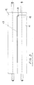
- each station there are at least two pairs of rollers consisting of one Top roller 10 and a bottom roller 11, namely a pair of rollers on the input side the station and another pair of rollers on the exit side of the Station.
- the roller pairs 10, 11 have the task of conveying the printing plates 13, which is why at least one roller can be driven in each pair of rollers.
- she also have the task of guiding the pressure plates 13, which is why the consequence of Nip is in a common flight and the lower roller 11 near her one end has a recess 12 for receiving a folded edge 14 of the pressure plates 13.
- the recesses 12 of the lower rollers are also in one common escape.
- the pair of rollers on the The output side of each station also has the task of the liquid squeeze from the pressure plate.
- the rollers 10, 11 therefore have e.g. one Sheath made of rubber, which is also used for conveying the pressure plates 13 produces the necessary frictional connection with them.
- the top rollers 10 pressed against the lower rollers 11.
- the top rollers 10 be resilient, in such a way that they are raised against spring force can be.
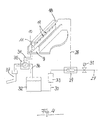
- the last pair of rollers 10, 11 serves in the gumming station 4 for applying a gum liquid to the top of the pressure plate 13.
- the top roller 10 is on the inlet side of the nip Spray tube 18 assigned, which extends parallel to the top roller 10 and from a sequence of nozzles 19 rubber liquid onto a distributor plate 20 sprayed, which rests against the upper roller 10 and the gum liquid as Film 21 distributed on the top roller 10, which it in the nip on the top the pressure plate 13 applies.
- nozzle openings 23 From which air into the outlet side of the nip is blown to prevent gum liquid from flowing through the nip runs through.
- Blowpipes 24 and 25 At a distance from the blowpipe 22 are two more Blowpipes 24 and 25 provided, one above and one below the Pressure plate 13, which has the pressure plate 13 on both sides with nozzle openings Apply cold or warm air to dry them.
- the dried printing plates 13 run on the outlet table 6, from which they can be removed.
- the spray tube and the rollers 10 and 11 must be in front of you every time the system is switched off, otherwise the rubber coating dries, the nozzles 19 of the spray tube clogged and the two rollers 10 and 11 sticks together, which will damage the system when you restart the system Roll cover would lead.
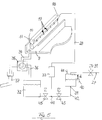
- FIG 4 shows that for the application of the gum liquid and for the subsequent one Rinsing the gum liquid known device.
- the spray pipe 18 is connected via a supply line to an OR valve 29, which on the one hand with the fresh water supply line 27 and on the other hand with a feed line 30 for Gum liquid is connected.
- the OR valve 29 connects the fresh water supply line 27 to the spray tube 18.
- the OR valve 29 connects the Spray tube 18 with a source for the gum liquid, consisting of a Tank 32 and a pump 33, which in the from the tank 32 to the OR valve 29th leading feed line 30 lies.
- the tub 9 has at its bottom an outlet at which a drain line 34 is connected, which leads to a 2/3 way valve 35, which in its one switching position the drain line 34 with a return to the tank 32 Line 36 and in its other switching position, which is shown in Figure 4 is, the drain line 34 connects to a waste water line 37.
- a drain line 34 is connected, which leads to a 2/3 way valve 35, which in its one switching position the drain line 34 with a return to the tank 32 Line 36 and in its other switching position, which is shown in Figure 4 is, the drain line 34 connects to a waste water line 37.
- the pump 33 For rinsing the pump 33 is first switched off and the 2/3 way valve 35 is switched over, so that it connects the drain pipe 34 to the sewage pipe 37, as shown in Figure 4. Then the solenoid valve 31 in the fresh water supply 27 opened and the spray tube 18 and the pair of rollers 10 and 11 rinsed until the gum liquid is washed off the rollers 10, 11. The Mixture of gum liquid and water flows into the waste water line 37.
- the object of the present invention is to show a way in which the sucking back of gum liquid into the fresh water supply line can be prevented without great effort.
- the fresh water supply line no more direct connection to the supply line to the Nozzles through which alternating gum and the essentially Flushing liquid consisting of the fresh water flows.
- the rinsing liquid can consist of pure fresh water. It is also possible, the fresh water additives favoring the rinsing process to add.
- the object of the invention is achieved in a simple and inexpensive manner. It only has to interrupt the fresh water supply and a reservoir be provided for the temporary storage of fresh water.
- the capacity of the storage container can be relatively small because the storage container can be continuously refilled from the fresh water supply.
- To this Purpose can be a level sensor to monitor the highest level and a level sensor to monitor a lower level in the reservoir be provided and these two level sensors can be a solenoid valve Control in the fresh water supply line so that the solenoid valve falls below the predetermined lower level opened and when reaching the predetermined maximum levels is closed.
- shut-off valve in the fresh water supply line a float switch is controlled, which when the highest is reached provided levels the shut-off valve closes and when the The shut-off valve in the fresh water supply line is below the maximum level increasingly opens.
- Another possibility is to use only one in the fresh water supply Shut-off valve, e.g. to provide a solenoid valve and the reservoir for limitation of the water level with an overflow.
- An excess amount of water can flow out through the overflow.
- the water level never reaches the mouth of the fresh water supply.
- the rinsing liquid can be fed from the storage container to the nozzles with a pump become. You could also use the reservoir for the rinsing liquid Arrange high so that the flushing liquid is fed to the nozzles solely by gravity can be. It is particularly preferred for the supply of the gum liquid and to provide the rinsing liquid with a common pump, which optionally with the tank for the gum liquid and with the storage container can be connected for the rinsing liquid. This way it is effective Forced flushing with minimal effort and safe separation of the fresh water network given by the gum liquid.
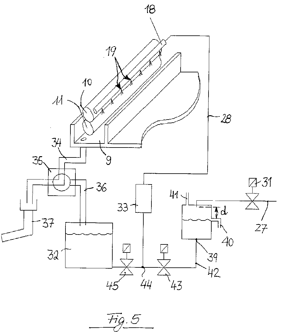
- FIG. 5 shows a schematic representation similar to Figure 4 an embodiment a device according to the invention in a system for which the representations in FIGS. 1 to 3 apply in the same way as examples.
- the device according to the invention differs from the known device in that the fresh water from the fresh water supply line 27 is not direct is fed into the feed line 28 to the spray tube 18, but into a storage container 38, which has an outlet 39 in the floor, at a height above the Bottom has an overflow pipe 40 and a cover with a ventilation opening 41.
- the fresh water supply leads from above into the reservoir 38 and opens at a distance d above the overflow pipe 40.
- the distance d is chosen so that sucking water back into the fresh water supply line 27 among all Circumstances is excluded.
- a line 42 leads from the outlet opening 39 and contains a solenoid valve 43 lies in the feed line 30 leading from the tank 32 to the pump 33, between the mouth 44 of the line 42 into the feed line 30 and the tank 32 is still another solenoid valve 45.
- These two solenoid valves 43 and 45 replace the OR valve 29 of the known device from FIG. 4.
- the device according to the invention agrees with the device in FIG 4 match. Matching parts are therefore with matching reference numbers designated. Instead of the two solenoid valves 43 and 45, one could 2/3 way valve can be used.
- the device according to the invention works as follows:
- the solenoid valves 31 and 43 When gumming, the solenoid valves 31 and 43 are closed, the solenoid valve 45 is open.
- the pump 33 sucks gum liquid from the tank 32 and feeds it into the spray tube 18, from which it emerges through the nozzles 19 and hits the top roller 10.
- the excess of gum liquid is in the Tray 9 collected and leaves through the drain line 34, which is connected to the return line 36 by the 2/3 way valve 35, so that the excess gum liquid is returned to the tank 32.
- the 2/3 way valve 35 is switched over so that the drain line 34 is connected to the sewage line 37.
- the solenoid valve 45 is closed and the solenoid valves 31 and 43 are opened.
- the pump 33 sucks in rinsing liquid, which is essentially fresh water, from the reservoir 38 and feeds it into the spray tube 18 from which it gets onto the rollers 10 and 11 so that they are rinsed off.
- the mixture of rinse water and gum liquid flows through the drain line 34 into the waste water line 37.
- the fresh water supply line 27 fresh water in the reservoir 38 refilled, at most, however the water level reaches the overflow pipe 40.
Landscapes
- Inking, Control Or Cleaning Of Printing Machines (AREA)
- Printing Plates And Materials Therefor (AREA)
Abstract
Description
- Figur 1
- zeigt die wesentlichen Elemente einer Anlage zum Waschen, Gummieren und Trocknen von Druckplatten in einer Schrägansicht ohne Gestell und Verkleidung, wie sie sich aus der EP 0 703 861 B1 ergibt,
- Figur 2
- zeigt als Detail einen Längsschnitt durch ein Walzenpaar in der Gummierstation mit anschließender Trocknungseinrichtung,
- Figur 3
- zeigt die Ansicht des Walzenpaares aus Figur 2 mit einer im Walzenspalt eingeklemmten Druckplatte, und
- Figur 4
- ist eine schematische Darstellung einer bekannten Einrichtung zum Spülen einer solchen Gummierstation.
- 1
- Einlauftisch
- 2
- Waschstation
- 3
- Spülstation
- 4
- Gummierungsstation
- 5
- Trocknungseinrichtung
- 6
- Auslauftisch
- 7
- Wanne
- 8
- Wanne
- 9
- Wanne
- 10
- Oberwalze
- 11
- Unterwalze
- 12
- Einstich
- 13
- Druckplatten
- 14
- Rand
- 15 16 17 18
- Sprührohr
- 19
- Düsen
- 20
- Verteilerblech
- 21
- Film
- 22
- Blasrohr
- 23
- Düsenöffnungen
- 24
- Blasrohr
- 25
- Blasrohr
- 26
- Förderrichtung
- 27
- Frischwasserzuleitung
- 28
- Zuleitung zum Sprührohr
- 29
- ODER - Ventil
- 30
- Speiseleitung
- 31
- Absperrventil (Magnetventil)
- 32
- Tank
- 33
- Pumpe
- 34
- Ablaufleitung
- 35
- 2/3 - Wege - Ventil
- 36
- rückführende Leitung
- 37
- Abwasserleitung
- 38
- Vorratsbehälter
Claims (8)
- Einrichtung zum Spülen einer Gummierstation in einer Anlage zum Waschen, Gummieren und Trocknen von Druckplatten, mit den folgenden Merkmalen:a) In der Gummierstation (4) ist wenigstens ein Paar Walzen (10, 11) vorgesehen, welche mit waagerechter Drehachse übereinander angeordnet sind;b) zwischen den Walzen (10, 11) besteht ein Spalt, durch welchen die Druckplatten (13) hindurchbewegbar sind, wobei die beiden Walzen (10, 11) die Druckplatten (13) an deren Oberseite und Unterseite berühren;c) entlang der oberen Walze (10) sind Düsen (19) angeordnet, durch welche eine Flüssigkeit auf die obere Walze (11) auftragbar ist;d) die Düsen (19) sind wahlweise mit einer Quelle (32, 33) für eine Gummierflüssigkeit und mit einer Quelle (38, 33, 27) für eine im wesentlichen aus Wasser bestehende Spülflüssigkeit verbindbar;e) unter dem Walzenpaar (10, 11) ist eine Wanne (9) angeordnet, welche die von den Walzen (10, 11) und Druckplatten (13) ablaufende Gummierflüssigkeit und Spülflüssigkeit auffängt;f) an die Wanne (9) sind Mittel (34, 35, 36, 37) zum Ableiten der Gummierflüssigkeit und der Spülflüssigkeit angeschlossen; (Oberbegriff)g) die Quelle (38, 33, 27) für die Spülflüssigkeit umfaßt einen Vorratsbehälter (38) vorgesehen, welcher mit Mitteln (40) zum Begrenzen des Niveaus der Spülflüssigkeit vorgesehen ist;h) der Vorratsbehälter (38) hat einen Anschluß (27) für Frischwasser, dessen Mündung über dem höchsten Niveau der Spülflüssigkeit im Vorratsbehälter (38) liegt.
(Kennzeichen) - Einrichtung nach Anspruch 1, dadurch gekennzeichnet, daß der Anschluß (27) für das Frischwasser von den Mitteln zum Begrenzen des Niveaus absperrbar ist.
- Einrichtung nach Anspruch 1 oder 2, dadurch gekennzeichnet, daß als Mittel zum Begrenzen des Niveaus ein Niveausensor vorgesehen ist.
- Einrichtung nach Anspruch 1, 2 oder 3, dadurch gekennzeichnet, daß der Anschluß (27) für das Frischwasser durch Mittel öffenbar ist, welche auf ein Niveau unter dem höchsten Niveau der Spülflüssigkeit ansprechen.
- Einrichtung nach Anspruch 1, 2 oder 3, dadurch gekennzeichnet, daß im Vorratsbehälter (38) ein Schwimmerschalter vorgesehen ist, welcher ein in der Frischwasserzuleitung (27) liegendes Ventil steuert.
- Einrichtung nach Anspruch 1 oder 2, dadurch gekennzeichnet, daß als Mittel zum Begrenzen des Niveaus ein Überlauf (40) vorgesehen ist.
- Einrichtung nach einem der vorstehenden Ansprüche, dadurch gekennzeichnet, daß in der Frischwasserzuleitung (27) ein Magnetventil (31) vorgesehen ist.
- Einrichtung nach einem der vorstehenden Ansprüche, dadurch gekennzeichnet, daß eine Pumpe (33) vorgesehen ist, welche mit ihrer Saugseite wahlweise mit einem Tank (32) für die Gummierflüssigkeit und mit dem Vorratsbehälter (38) für die Spülflüssigkeit verbindbar ist und mit ihrer Druckseite mit den Düsen (19) verbunden ist.
Applications Claiming Priority (2)
| Application Number | Priority Date | Filing Date | Title |
|---|---|---|---|
| DE20001524U DE20001524U1 (de) | 2000-01-28 | 2000-01-28 | Einrichtung zum Spülen einer Gummierstation in einer Anlage zum Waschen, Gummieren und Trocknen von Druckplatten |
| DE20001524U | 2000-01-28 |
Publications (2)
| Publication Number | Publication Date |
|---|---|
| EP1120252A2 true EP1120252A2 (de) | 2001-08-01 |
| EP1120252A3 EP1120252A3 (de) | 2002-09-18 |
Family
ID=7936543
Family Applications (1)
| Application Number | Title | Priority Date | Filing Date |
|---|---|---|---|
| EP01101864A Withdrawn EP1120252A3 (de) | 2000-01-28 | 2001-01-26 | Einrichtung zum Spülen einer Gummierstation in einer Anlage zum Waschen, Gummieren und Trocknen von Druckplatten |
Country Status (2)
| Country | Link |
|---|---|
| EP (1) | EP1120252A3 (de) |
| DE (1) | DE20001524U1 (de) |
Cited By (2)
| Publication number | Priority date | Publication date | Assignee | Title |
|---|---|---|---|---|
| CN1328069C (zh) * | 2001-11-06 | 2007-07-25 | 曼.罗兰.德鲁克马辛伦公司 | 清洗和清除印刷印版和橡胶滚筒的印刷表面的方法 |
| CN105775880A (zh) * | 2014-12-24 | 2016-07-20 | 重庆鑫仕达包装设备有限公司 | 一种复合机 |
Families Citing this family (1)
| Publication number | Priority date | Publication date | Assignee | Title |
|---|---|---|---|---|
| DE102006027768B3 (de) * | 2006-06-16 | 2007-10-11 | Technotrans Ag | Sprühleiste für Waschflüssigkeit |
Family Cites Families (3)
| Publication number | Priority date | Publication date | Assignee | Title |
|---|---|---|---|---|
| US5367982A (en) * | 1993-02-25 | 1994-11-29 | Howard W. DeMoore | Automatic coating circulation and wash-up system for printing presses |
| DE9310649U1 (de) * | 1993-06-18 | 1993-09-16 | Hanosek, Peter, 75236 Kämpfelbach | Vorrichtung zum Waschen und Trocknen von Druckplatten |
| IES960111A2 (en) * | 1996-02-09 | 1996-06-12 | Elsen Ltd | An apparatus for washing printing plates |
-
2000
- 2000-01-28 DE DE20001524U patent/DE20001524U1/de not_active Expired - Lifetime
-
2001
- 2001-01-26 EP EP01101864A patent/EP1120252A3/de not_active Withdrawn
Cited By (3)
| Publication number | Priority date | Publication date | Assignee | Title |
|---|---|---|---|---|
| CN1328069C (zh) * | 2001-11-06 | 2007-07-25 | 曼.罗兰.德鲁克马辛伦公司 | 清洗和清除印刷印版和橡胶滚筒的印刷表面的方法 |
| CN105775880A (zh) * | 2014-12-24 | 2016-07-20 | 重庆鑫仕达包装设备有限公司 | 一种复合机 |
| CN105775880B (zh) * | 2014-12-24 | 2023-06-23 | 重庆鑫仕达包装设备有限公司 | 一种复合机 |
Also Published As
| Publication number | Publication date |
|---|---|
| EP1120252A3 (de) | 2002-09-18 |
| DE20001524U1 (de) | 2000-05-04 |
Similar Documents
| Publication | Publication Date | Title |
|---|---|---|
| EP1474253A1 (de) | Vorrichtung zum trockenhalten von kaltband im auslauf von bandwalzanlagen | |
| DE1617959A1 (de) | Verfahren und Vorrichtung zur aseptischen Entfernung von Fluessigkeit von einem bahnfoermigen Verpackungsmaterial | |
| EP1772093A1 (de) | Vorrichtung zum Befeuchten und Entfeuchten eines Feuchtwischers | |
| DE2745498C3 (de) | Vorrichtung zur Steuerung eines Nachfüllens von Flüssigkeit in eine Reinigungsmischung | |
| DE4132350A1 (de) | Sanitaere vorrichtung | |
| DE60318708T2 (de) | Tragbare oberflächenbehandlungsvorrichtung | |
| EP1120252A2 (de) | Einrichtung zum Spülen einer Gummierstation in einer Anlage zum Waschen, Gummieren und Trocknen von Druckplatten | |
| EP1219224B1 (de) | Vorrichtung zum Befeuchten und Entfeuchten eines Feuchtwischers | |
| EP1198643A1 (de) | Auftragsvorrichtung | |
| DE20011821U1 (de) | Einrichtung zur Befeuchtung von Luft | |
| WO2009059779A2 (de) | Reinigungs-/trocknungsvorrichtung für das reinigen und/oder trocknen von polstern und/oder flächen in einem kraftfahrzeug | |
| DE69906521T2 (de) | Verfahren und vorrichtung in einer trockenreinigungsmaschine | |
| DE202013102761U1 (de) | Vorrichtung zur Oberflächenleimung einer Faserbahn | |
| DE1546211B2 (de) | Vorrichtung zum entfetten von streifenfoermigen material | |
| DE4236123C1 (de) | Vorrichtung zum Separieren und Trocknen von Kunststoffschnitzeln | |
| DE102004044041A1 (de) | Vorrichtung zum Entfeuchten oder Befeuchten eines Feuchtwischers | |
| DE3309636A1 (de) | Reinigungsautomat | |
| DE2638978A1 (de) | Einrichtung zum ausscheiden und wegfuehren ausgewaschener schmutzpartikel aus einer breitwaschmaschine fuer bahnfoermiges material | |
| DE3923460C2 (de) | ||
| DE112006002157T5 (de) | Verfahren und Anordnung zur Verbesserung der Verwendbarkeit einer gleitbeschickten Vorhangstreicheinrichtung und zur Verringerung des Verlustes von Streichwerkstoffen | |
| EP1618965A2 (de) | Vorrichtung für einen Farbwechsel beim Aufbringen eines über die Arbeitsbreite gleichmässig dünnen Flüssigkeitsfilmes auf eine Warenbahn | |
| DE1546211C3 (de) | Vorrichtung zum Entfetten von streifenförmigem Material | |
| DE1966792C2 (de) | Hebevorrichtung für mit Dickstoffen versetzte Abwasser o.dgl | |
| DE60018514T2 (de) | Vorrichtung zur Durchflussregelung in einem Luft-Flüssigkeits-Zentrifugalabscheider | |
| DE102004058570B3 (de) | Vorrichtung zur Zufuhr von Waschmittel |
Legal Events
| Date | Code | Title | Description |
|---|---|---|---|
| PUAI | Public reference made under article 153(3) epc to a published international application that has entered the european phase |
Free format text: ORIGINAL CODE: 0009012 |
|
| AK | Designated contracting states |
Kind code of ref document: A2 Designated state(s): AT BE CH CY DE DK ES FI FR GB GR IE IT LI LU MC NL PT SE TR |
|
| AX | Request for extension of the european patent |
Free format text: AL;LT;LV;MK;RO;SI |
|
| PUAL | Search report despatched |
Free format text: ORIGINAL CODE: 0009013 |
|
| AK | Designated contracting states |
Kind code of ref document: A3 Designated state(s): AT BE CH CY DE DK ES FI FR GB GR IE IT LI LU MC NL PT SE TR |
|
| AX | Request for extension of the european patent |
Free format text: AL;LT;LV;MK;RO;SI |
|
| AKX | Designation fees paid | ||
| REG | Reference to a national code |
Ref country code: DE Ref legal event code: 8566 |
|
| STAA | Information on the status of an ep patent application or granted ep patent |
Free format text: STATUS: THE APPLICATION IS DEEMED TO BE WITHDRAWN |
|
| 18D | Application deemed to be withdrawn |
Effective date: 20030319 |