EP1119411B1 - Impregnation process for catalysts - Google Patents
Impregnation process for catalysts Download PDFInfo
- Publication number
- EP1119411B1 EP1119411B1 EP99944753A EP99944753A EP1119411B1 EP 1119411 B1 EP1119411 B1 EP 1119411B1 EP 99944753 A EP99944753 A EP 99944753A EP 99944753 A EP99944753 A EP 99944753A EP 1119411 B1 EP1119411 B1 EP 1119411B1
- Authority
- EP
- European Patent Office
- Prior art keywords
- loi
- treatment stage
- support
- impregnation step
- slurry
- Prior art date
- Legal status (The legal status is an assumption and is not a legal conclusion. Google has not performed a legal analysis and makes no representation as to the accuracy of the status listed.)
- Expired - Lifetime
Links
Images


Classifications
-
- B—PERFORMING OPERATIONS; TRANSPORTING
- B01—PHYSICAL OR CHEMICAL PROCESSES OR APPARATUS IN GENERAL
- B01J—CHEMICAL OR PHYSICAL PROCESSES, e.g. CATALYSIS OR COLLOID CHEMISTRY; THEIR RELEVANT APPARATUS
- B01J37/00—Processes, in general, for preparing catalysts; Processes, in general, for activation of catalysts
- B01J37/02—Impregnation, coating or precipitation
- B01J37/0201—Impregnation
-
- B—PERFORMING OPERATIONS; TRANSPORTING
- B01—PHYSICAL OR CHEMICAL PROCESSES OR APPARATUS IN GENERAL
- B01J—CHEMICAL OR PHYSICAL PROCESSES, e.g. CATALYSIS OR COLLOID CHEMISTRY; THEIR RELEVANT APPARATUS
- B01J23/00—Catalysts comprising metals or metal oxides or hydroxides, not provided for in group B01J21/00
- B01J23/70—Catalysts comprising metals or metal oxides or hydroxides, not provided for in group B01J21/00 of the iron group metals or copper
- B01J23/74—Iron group metals
- B01J23/75—Cobalt
-
- B—PERFORMING OPERATIONS; TRANSPORTING
- B01—PHYSICAL OR CHEMICAL PROCESSES OR APPARATUS IN GENERAL
- B01J—CHEMICAL OR PHYSICAL PROCESSES, e.g. CATALYSIS OR COLLOID CHEMISTRY; THEIR RELEVANT APPARATUS
- B01J23/00—Catalysts comprising metals or metal oxides or hydroxides, not provided for in group B01J21/00
- B01J23/70—Catalysts comprising metals or metal oxides or hydroxides, not provided for in group B01J21/00 of the iron group metals or copper
- B01J23/89—Catalysts comprising metals or metal oxides or hydroxides, not provided for in group B01J21/00 of the iron group metals or copper combined with noble metals
- B01J23/8913—Cobalt and noble metals
-
- B—PERFORMING OPERATIONS; TRANSPORTING
- B01—PHYSICAL OR CHEMICAL PROCESSES OR APPARATUS IN GENERAL
- B01J—CHEMICAL OR PHYSICAL PROCESSES, e.g. CATALYSIS OR COLLOID CHEMISTRY; THEIR RELEVANT APPARATUS
- B01J37/00—Processes, in general, for preparing catalysts; Processes, in general, for activation of catalysts
- B01J37/02—Impregnation, coating or precipitation
- B01J37/0201—Impregnation
- B01J37/0205—Impregnation in several steps
-
- B—PERFORMING OPERATIONS; TRANSPORTING
- B01—PHYSICAL OR CHEMICAL PROCESSES OR APPARATUS IN GENERAL
- B01J—CHEMICAL OR PHYSICAL PROCESSES, e.g. CATALYSIS OR COLLOID CHEMISTRY; THEIR RELEVANT APPARATUS
- B01J37/00—Processes, in general, for preparing catalysts; Processes, in general, for activation of catalysts
- B01J37/02—Impregnation, coating or precipitation
- B01J37/0236—Drying, e.g. preparing a suspension, adding a soluble salt and drying
-
- B—PERFORMING OPERATIONS; TRANSPORTING
- B01—PHYSICAL OR CHEMICAL PROCESSES OR APPARATUS IN GENERAL
- B01J—CHEMICAL OR PHYSICAL PROCESSES, e.g. CATALYSIS OR COLLOID CHEMISTRY; THEIR RELEVANT APPARATUS
- B01J37/00—Processes, in general, for preparing catalysts; Processes, in general, for activation of catalysts
- B01J37/08—Heat treatment
Definitions
- THIS INVENTION relates to catalysts. It relates in particular to a process for preparing a catalyst precursor.
- a process for preparing a catalyst precursor which process comprises
- the resultant catalyst precursor is, in practice, subjected to reduction, in order to obtain a catalyst.
- the porous oxidic catalyst support may, in particular, be in particulate form.
- any commercially available oxidic catalyst support can be used.
- catalyst supports that can be used are alumina (Al 2 O 3 ) and titania (TiO 2 ).
- the support preferably has an average pore diameter between 8 and 50 nanometers, more preferably between 10 and 15 nanometers.
- the support pore volume may be between 0,1 and 1ml/g, preferably between 0,3 and 0,9ml/g.
- the average particle size may be between 1 and 500 micrometers, preferably between 10 and 250 micrometers, still more preferably between 45 and 200 micrometers.
- Alumina is preferred as the support, and the invention is described further hereunder with reference to alumina as the support.
- the active catalyst component can, at least in principle, be any known Fischer-Tropsch active component such as cobalt (Co), iron (Fe), nickel (Ni) or ruthenium (Ru); however, cobalt (Co) is preferred.
- a cobalt precursor can be used.
- cobalt nitrate Co(NO 3 ) 2 .6H 2 O is preferably used.
- Co(NO 3 ) 2 .6H 2 O may initially be used in the initial treatment stage, where x is the BET pore volume of the alumina support in ml/g, and y is the mass of alumina support to be impregnated, in kg.
- the process may include initially dissolving the Co(NO 3 ) 2 .6H 2 O in the water, which is preferably distilled water. Sufficient water may be used such that the volume of the solution is greater than xyl, and preferably is about 2xyl.
- this solution may be heated to a temperature between 60°C and 95°C, with the support then being added to the solution at atmospheric pressure, to form the slurry.
- the slurry may be mixed, preferably on a continuous basis, eg by means of an internal rotating screw in a conical vacuum drier in which the slurry is held.
- vacuum may then gradually be applied to the slurry, preferably under continuous mixing, eg stirring, thereof, at the temperature T 1 , which may be the same as the temperature to which the solution is initially heated, or different therefrom.
- T 1 the temperature to which the solution is initially heated, or different therefrom.
- the sub-atmospheric pressure or vacuum P 1 that is applied during the initial treatment stage is thus between atmospheric pressure and 20kPa(a).
- the vacuum may be about 20kPa(a) for a slurry temperature of 60°C, and about 83kPa(a) for a slurry temperature of 95°C.
- the initial treatment stage is preferably continued until the loss on ignition ('LOI') of the impregnated alumina support is 1,2 times LOI iw , ie 1,2 times the LOI at the point of incipient wetness ('iw').
- Incipient wetness occurs when all the pores of the support are filled with liquid and there is no excess moisture, over and above the liquid required to fill the pores, present.
- the initial treatment time will be up to 3 hours or more.
- Loss on ignition is defined as the mass % loss observed during complete calcination, ie during decomposition to Co 3 O 4 /Al 2 O 3 , experimentally to be determined as the mass % loss observed during calcination at 400°C, ie at a temperature sufficiently high to ensure quantitative decomposition of cobalt nitrate to Co 3 O 4 , but too low in order to effect the undesired formation of cobalt aluminates.
- the LOI value at the state of incipient wetness can be expressed as a function of the pore volume of the support as well as the amount of catalyst active component to be impregnated.
- the pore volume of the support, prior to impregnation, is as stated hereinbefore, equal to x ml/g.
- the amount of Co(NO 3 ) 2 .6H 2 O to be impregnated is M gram per gram of support material, and will fall within the range: 1,18x to 1,82x gram per gram support material. M is thus determined by the amount of Co(NO 3 ) 2 .6H 2 O initially used.
- Vacuum drying under these specific conditions should be maintained until a clearly defined maximum required LOI value is reached, which value depends on the need to store the dried material for a certain period of time before calcination can be executed, as hereinafter described, and this maximum required LOI value is smaller than, or equal to, 0,90 times LOI iw .
- the calcination of this dried impregnated support may be effected in a fluidized bed, or a rotary kiln, calciner at a temperature from 200°C to 300°C, preferably at about 250°C.
- the process thus involves using a slurry, ie an excess of moisture, to achieve impregnation of the support; thereafter drying the impregnated support in a gradual manner during the initial treatment stage until 1,2 times LOI iw ; whereafter the more forceful drying of the subsequent treatment stage is effected until the maximum required LOI value is attained.
- Sufficient cobalt nitrate may initially be used to obtain a cobalt loading between 5g Co/100g support and 70g Co/100g support, preferably between 20g Co/100g support and 40g Co/100g support, more preferably between 25g Co/100g support and 35g Co/100g support.
- the optimum cobalt loading is defined as the maximum cobalt loading at which the cobalt utilization is still optimum.
- a direct proportionality between cobalt loading and catalyst productivity existed up to a cobalt loading of 30g Co/100gAl 2 O 3 , for a Al 2 O 3 support material with a pore volume of about 0,5ml/g, and an average pore diameter of 12 nanometer.
- the calcined catalyst precursor obtained from the abovementioned initial or first impregnation step (ie 18,4g CO/100gAl 2 O 3 in the case of a support material with a pore volume of 0,5ml/g), must be subjected to a further impregnation, drying and calcination in a second impregnation step.
- the second impregnation step may then comprise
- the catalyst precursor is, in practice, reduced, to obtain a catalyst.
- the amount of Co(NO 3 ) 2 .6H 2 O used during the second impregnation step may be from 1,18x 1 y 1 to 1,82x 1 y 1 kg where x 1 is the BET pore volume of the calcined material from the first impregnation step, in ml/g, and y 1 is the mass of calcined material from the first impregnation step to be impregnated in the second impregnation step, in kg.
- This range of cobalt nitrate allows for a limited flexibility with respect to the cobalt loading of the resultant catalyst to be broadened by support tailoring.
- Table 2 provides the correlation between the pore volume of the starting alumina, ie x ml/g, and the empirically derived maximum attainable cobalt loading in a two-step impregnation procedure as hereinbefore described.
- the starting alumina support must have a pore volume ⁇ 0,43ml/g.
- This amount of cobalt nitrate may initially be dissolved in water, which is preferably distilled water. Sufficient water may be used such that the volume of the solution is >x 1 y 1 l, preferably about 2x 1 y 1 l. This solution may then be heated to a temperature between 60 and 95°C. To this solution, the final inventory of y 1 kg of the first impregnation step material, ie the catalyst precursor of the first impregnation and calcination step, may be added at atmospheric pressure, whilst continuous mixing of the slurry is maintained, eg by means of an internal rotating screw in a conical vacuum drier.
- water which is preferably distilled water.
- Sufficient water may be used such that the volume of the solution is >x 1 y 1 l, preferably about 2x 1 y 1 l.
- This solution may then be heated to a temperature between 60 and 95°C.
- the final inventory of y 1 kg of the first impregnation step material ie
- vacuum may then gradually be applied to the slurry, preferably under continuous mixing, eg stirring, thereof, at the temperature T 1 ', which may be the same as the temperature to which the solution is initially heated, or different therefrom.
- T 1 ' which may be the same as the temperature to which the solution is initially heated, or different therefrom.
- the initial treatment stage of the second impregnation step is preferably continued until the LOI of the impregnated material is reduced to a point where it is 1,2 times LOI iw .
- the initial treatment time will be up to 3 hours or more.
- the sub-atmospheric pressure or vacuum P 1 ' that is applied during the initial treatment stage is thus between atmospheric pressure and 20kPa(a).
- the vacuum may be about 20kPa(a) for a slurry temperature of 60°C and about 83kPa(a) for a slurry temperature of 95°C.
- this gradual drying procedure until the LOI is 1,2 times LOI iw ensures that about 83% of the cobalt nitrate is quantitatively drawn into the pores of the catalyst precursor without the occurrence of localized saturation, which results in premature crystallization of cobalt nitrate.
- aggressive evacuation eg increased vacuum pump suction capacity when a vacuum pump is used, may be applied, in the subsequent treatment stage of the second impregnation step; at the same time, it is ensured that the support temperature is controlled at between 60°C and 95°C.
- a vacuum drier in which the impregnated material is contained in the form of a bed
- an increased setting of the vacuum drier wall temperature is used, thereby ensuring that the bed temperature is controlled between 60°C and 95°C, under continuous mixing, eg stirring.
- maximum vacuum ⁇ 20kPa(a)
- the bed temperature does not drop below 60°C, under continuous mixing. This constitutes the subsequent treatment stage.
- vacuum drying during the subsequent treatment stage preferably proceeds in an uninterrupted fashion, at the conditions: >60°C, but not higher than 95°C, and at the minimum pressure which is attainable, with this pressure being ⁇ 20kPa(a)
- Vacuum drying under these specific conditions should be maintained until a clearly defined maximum LOI value is reached, which value depends on the need to store the dried material for a certain period of time before calcination can be executed, as hereinafter described, and this maximum required LOI value is smaller than, or equal to, 0,90 times LOI iw .
- the calcination of this dried impregnated material may be effected in a fluidized bed, or a rotary kiln, calciner at a temperature from 200°C to 300°C, preferably at about 250°C.
- a water soluble precursor salt of palladium (Pd) or platinum (Pt) may be added, as a dopant capable of enhancing the reducibility of the active component.
- the mass proportion of the palladium or platinum metal to the cobalt metal may be between 0,01:100 to 0,3:100.
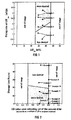
- this may be done by matching the experimental data to an empirical equation, eg y a Inx+b, and calculating the derivative at the point of incipient wetness. After having determined a suitable equation to fit the experimental data, this type of equation should be used exclusively to calculate the drying rate, ie the tangent at the point of incipient wetness, for all drying profiles.
- the impregnation and drying of the catalyst support in the sub-atmospheric environment ie the initial and subsequent treatment stages of the first and second impregnation steps, can be performed in, for example, a conical vacuum drier with rotating screw or a tumbling vacuum drier, preferably a conical vacuum drier.
- the desired drying profile can be achieved by decreasing the sub-atmospheric pressure, by more efficient mixing, by increasing the temperature of the vacuum drier wall, or by the introduction of hot air during the subsequent treatment stage, but preferably is achieved by more efficient mixing.
- the maximum allowable storage time at ambient conditions in a dry environment between the catalyst support impregnation/drying and the catalyst precursor calcination is a direct function of LOI unload , ie the LOI at which the impregnated support drying, ie the subsequent treatment stage, was terminated and the dried impregnated material unloaded from the vacuum drying equipment.
- the maximum allowable storage time before calcination should preferably be less than ((-8,1/LOI iw )LOI unload +26,2) hours, which thus results in a catalyst that has a more desired activity.
- the support may be added to the solution at ambient temperature, whereafter the temperature of the slurry is increased to a minimum of 60°C and a maximum of 95°C prior to evacuation to a vacuum of ⁇ 20kPa(a).
- the temperature may then be increased slowly, to ensure that the gradual treatment, ie without excessive boiling of the slurry, is effected.
- the catalyst obtained is particularly suitable for use as a Fischer-Tropsch catalyst to catalyze the Fischer-Tropsch reaction of a synthesis gas, comprising hydrogen and carbon monoxide, to produce Fischer-Tropsch products.
- An alumina supported cobalt catalyst precursor was prepared according to the process of the invention.
- a solution of 17,4 kg of Co(NO 3 ) 2 .6H 2 O,9,6g of (NH 3 ) 4 Pt(NO 3 ) 2 , and 11 kg of distilled water was mixed with 20,0kg of a gamma alumina support (Puralox SCCa 5/150, pore volume of 0,48ml/g, from Condea Chemie GmbH of Uberseering 40, 22297 Hamburg, Germany) by adding the support to the solution.
- a gamma alumina support Pulox SCCa 5/150, pore volume of 0,48ml/g, from Condea Chemie GmbH of Uberseering 40, 22297 Hamburg, Germany
- the temperature of this slurry was increased to 60°C after which a vacuum of 20kPa(a) was applied. During the first 3 hours of drying, ie during an initial treatment stage, the temperature was increased slowly and reached 95°C after 3 hours.
- the LOI iw was calculated by using Equation 1, and applying 0,48(ml/g) for x and 0,87(g Co(NO 3 ) 2 .6H 2 O per gram alumina) for M. This gives a LOI iw of 35%.
- the LOI values of samples of the impregnated material were determined by calcining a sample, taken from the vacuum drier during the impregnation/drying stage, at 400°C in air for 10 minutes.
- the temperature of this slurry was increased to 60°C after which a vacuum of 20kPa was applied.
- the LOI iw can again be calculated by using Equation 1, and applying 0,36(ml/g) (measured) for x 1 and 0,47(g Co(NO 3 ) 2 .6H 2 O per gram alumina) for M. This results in a LOI iw of 29%.
- the LOI after 3 hours was 37,0%, ie 1,28LOI iw .
- the drying was performed more aggressively, ie the pressure was decreased to 7kPa(a).
- the LOI was 26,8%, ie 0,92LOI iw .
- this subsequent treatment stage was terminated and the resultant dried impregnated material was calcined immediately at 250°C, to obtain a catalyst precursor.
- a catalyst precursor was prepared according to Example 1 except that the dried impregnated material was stored in a dry environment at ambient temperature for 48 hours after each impregnation step, before calcination thereof.
- a catalyst precursor was prepared according to Example 1 except that the dried impregnated material was stored in a dry environment at ambient temperature for 15 hours after each subsequent impregnation step, before calcination thereof.
- catalyst ie properly externally reduced catalyst precursors of Examples 1 to 3, ranging between 38 and 150 micron, were suspended in 300ml molten wax and loaded in a CSTR with an internal volume of 500ml.
- the feed gas consisted of hydrogen and carbon monoxide in a H 2 /CO molar ratio from 1,5/1 to 2,3/1.
- This reactor was electrically heated and sufficiently high stirrer speeds were employed so as to eliminate any gas-liquid mass transfer limitations.
- the feed flow was controlled by means of Brooks mass flow controllers, and space velocities ranging from 2 to 4 m 3 n /(h.kg catalyst) were used.
- GC analyses of the permanent gases as well as the volatile overhead hydrocarbons were used in order to characterize the product spectra.
- All catalyst precursors were reduced prior to synthesis in a tubular reactor at a pure hydrogen space velocity of 2500h -1 and atmospheric pressure.
- the temperature was increased from room temperature to 350°C to 425°C at a rate of 1°C/min, after which isothermal conditions were maintained for 6 to 16 hours.
- Fischer-Tropsch slurry phase synthesis performance results are shown in Table 4. Fischer-Tropsch slurry phase synthesis results
- Example 1 Example 2
- Example 3 run analysis 233$ 242$ 265$ Synthesis conditions Calcined catalyst mass (g) 22,1 21,1 20,7 Reactor temperature (°C) 221 222 220 Reactor pressure (bar) 20,5 20,0 20,3 Time on stream (h) 15,5 15,0 15,3 Feed gas composition: H 2 (vol%) 54,6 54,1 55,5 CO (vol%) 28,5 28,4 27,5 CO 2 (vol%) 0,58 0,56 0,50
- Synthesis performance Conversion % syngas 76,0 67,7 76,8 Relative intrinsic specific
- r FT (k FT P H2 P CO )/(1+KP CO ) 2 the Arrhenius derived pre-exponential factor of k FT was estimated for each of the reported runs.
- the relative intrinsic specific Fischer-Tropsch activity is defined as (pre-exponential factor of catalyst z)/(pre-exponential factor of catalyst of Example 1/2), in which catalyst z can be the catalyst of Example 2/2, 3/2, or 4/2.
- the more desired relative intrinsic Fischer-Tropsch activity is ⁇ 0,93, and subsequently the less desired relative intrinsic Fischer-Tropsch activity is ⁇ 0,93.
- a catalyst precursor was prepared according to Example 1 except that there was no stirring during the first and second impregnation steps.
- a catalyst precursor was prepared according to Example 1, except that the dried impregnated material was unloaded during the first impregnation step at an LOI of 31%, ie 0,89LOI iw . After unloading, the dried impregnated material was calcined immediately at 250°C. During the second impregnation step, the dried impregnated material was unloaded at a LOI of 26%, ie 0,90LOI iw . After unloading, the dried impregnated material was calcined immediately at 250°C.
- An alumina supported cobalt catalyst precursor was prepared according to the process of the invention.
- a solution of 221,13kg of Co(NO 3 ) 2 .6H 2 O, 121,5g of (NH 3 ) 4 Pt(NO 3 ) 2 , and 180,91kg of distilled water was mixed with 270,0kg of a gamma alumina support (Condea SCCa 5/150, pore volume of 0,45ml/g, from Condea Chemie GmbH of Uberseering 40, 22297 Hamburg, Germany) by adding the support to the solution.
- a gamma alumina support Condea SCCa 5/150, pore volume of 0,45ml/g, from Condea Chemie GmbH of Uberseering 40, 22297 Hamburg, Germany
- the temperature of this slurry was increased to 60°C and a vacuum of 20kPa was applied. During the first 3 hours of drying, ie during an initial treatment stage, the temperature was increased slowly and reached 95°C after 3 hours.
- the LOI iw can be calculated by using equation 1, and applying 0,45 (ml/g) for x and 0,82 (g Co(NO 3 ) 2 .6H 2 O per gram alumina) for M. This results in a LOI iw of 33%.
- the LOI value was determined as described in Example 1. The LOI after 3 hours was 41,8%, ie 1,28LOI iw .
- the pressure was decreased to 12kPa(a) and after 8 hours, as determined from the start of the initial treatment stage, the LOI was found to be 30,5%, ie 0,9LOI iw .
- the dried impregnated material was calcined at 250°C after a 1 hour waiting time between terminating the subsequent treatment stage and starting the calcination stage.
- a second impregnation step was performed.
- a solution of 171,24kg of Co(NO 3 ) 2 .6H 2 O, 269,2g of (NH 3 ) 4 Pt(NO 3 ) 2 , and 240,1kg of distilled water was mixed with 330kg of the calcined material from the first impregnation step, by adding the calcined material to the solution.
- the temperature of this slurry was increased to 60°C and a vacuum of 20kPa was applied.
- the LOI iw can again be calculated by using Equation 1, and applying 0,35 (ml/g) for x and 0,52 (g Co(NO 3 ) 2 .6H 2 O per gram alumina) for M. This results in a LOI iw of 28%.
- the temperature was increased slowly and reached 95°C after 3 hours.
- the LOI after 3 hours was 38,5%, ie 1,38 LOI iw .
- the pressure was decreased to 12kPa(a)
- the LOI was found to be 25,0%, ie 0,89LOI iw .
- the dried impregnated material was calcined at 250°C after a 1 hour waiting time between terminating the subsequent treatment stage and starting the calcination.
- a catalyst precursor was prepared according to Example 1 except that the dried impregnated material was stored in a dry environment at ambient temperature for 26 hours after the subsequent treatment stage of the second impregnation step, before calcination thereof.
- An alumina supported cobalt catalyst precursor was prepared according to the process of the invention.
- a solution of 17,4kg of Co(NO 3 ) 2 .6H 2 O, 9,6g of (NH 3 ) 4 Pt(NO 3 ) 2 , and 11kg of distilled water was mixed with 20,0kg of a gamma alumina support (Condea SCCa 5/150, pore volume of 0,48ml/g, from Condea Chemie GmbH of Uberseering 40, 22297 Hamburg, Germany) by adding the support to the solution.
- a gamma alumina support Condea SCCa 5/150, pore volume of 0,48ml/g, from Condea Chemie GmbH of Uberseering 40, 22297 Hamburg, Germany
- the LOI iw can be calculated by using Equation 1, and applying 0,48 (ml/g) for x and 0,87 (g Co(NO 3 ) 2 .6H 2 O per gram alumina) for M. This results in a LOI iw of 35%.
- the LOI after 3 hours was 42,1%, ie 1,20LOI iw .
- the pressure was decreased to 7 kPa(a), and after 7 hours, as determined from the start of the initial treatment stage the LOI was found to be 29,5%, ie 0,84LOI iw .
- the dried impregnated material was calcined immediately at 250°C.
- a second impregnation step was performed.
- a solution of 9,4kg of Co(NO 3 ) 2 .6H 2 O, 15,7g of (NH 3 ) 4 Pt(NO 3 ) 2 , and 15,1kg of distilled water was mixed with 20,0kg of calcined material from the first impregnation step, by adding the calcined material to the solution.
- the temperature of this slurry was increased to 60°C and a vacuum of 20kPa was applied.
- the LOI iw can again be calculated by using Equation 1, and applying 0,36 (ml/g) for x and 0,47 (g Co(NO 3 ) 2 .6H 2 O per gram alumina) for M. This results in a LOI iw of 29%.
- the temperature was increased slowly and reached 95°C after 3 hours.
- the LOI after 3 hours was 37,0%, ie 1,28LOI iw .
- the pressure was decreased to 7kPa(a), and after 7 hours, as determined from the start of the initial treatment stage of the second impregnation step, the LOI was found to be 25,0%, ie 0,86LOI iw .
- the impregnated and dried material was then stored in a dry environment at ambient temperature for 6 hours before calcination thereof.
- a catalyst precursor was prepared according to Example 8 except that the dried impregnated material was stored in a dry environment at ambient temperature for 35 hours after the subsequent treatment stage of the second impregnation step, before calcination thereof.
- a catalyst precursor was prepared according to Example 8 except that the dried impregnated material was stored in a dry environment at ambient temperature for 16 hours after the subsequent treatment stage of the second impregnation step, and before calcination thereof.
- a catalyst precursor was prepared according to Example 8 except that the dried impregnated material was stored in a dry environment at ambient temperature for 22 hours after the subsequent treatment stage of the second impregnation step, and before calcination thereof.
- Fischer-Tropsch synthesis is the conversion of synthesis gas to higher hydrocarbons, eg petrol, diesel, wax.
- Synthesis gas ie a gas mixture with hydrogen and carbon monoxide as the main components, can be produced from natural gas by processes well known to those skilled in the art, for example autothermal reforming or partial oxidation of natural gas.
- the Fischer-Tropsch synthesis process can be performed by using iron, nickel, cobalt, or ruthenium based catalysts.
- the catalysts can be used in fixed, slurry, and fluidized bed Fischer-Tropsch applications. It is known that supported cobalt based slurry phase Fischer-Tropsch catalysts produce a wax product. This wax product can be used as such, or it can, for example, be hydrocracked to petrol and diesel by processes known in the art.
- the Applicant has thus surprisingly found that by optimizing the drying procedure through ensuring that a particular drying profile is met during impregnation and drying and that, if a waiting period was required, the impregnated material is further dried to a set specification and the dried material is calcined within a set period of time, uniform catalysts of acceptable activities can be prepared.
- the present invention thus involves the optimization of a drying procedure for the preparation of a catalyst precursor from which can be obtained a catalyst with excellent Fischer-Tropsch synthesis behaviour and resulting in high activity. More particularly, this invention provides efficient drying of the impregnated material during catalyst precursor preparation, and once dried, the excellent properties of the catalyst introduced during drying are maintained until the calcination thereof.
Landscapes
- Chemical & Material Sciences (AREA)
- Engineering & Computer Science (AREA)
- Materials Engineering (AREA)
- Organic Chemistry (AREA)
- Chemical Kinetics & Catalysis (AREA)
- Physics & Mathematics (AREA)
- Thermal Sciences (AREA)
- Catalysts (AREA)
- Production Of Liquid Hydrocarbon Mixture For Refining Petroleum (AREA)
- Organic Low-Molecular-Weight Compounds And Preparation Thereof (AREA)
Applications Claiming Priority (5)
| Application Number | Priority Date | Filing Date | Title |
|---|---|---|---|
| ZA9809056 | 1998-10-05 | ||
| ZA989056 | 1998-10-05 | ||
| ZA9811334 | 1998-12-10 | ||
| ZA9811334 | 1998-12-10 | ||
| PCT/IB1999/001626 WO2000020116A1 (en) | 1998-10-05 | 1999-10-04 | Impregnation process for catalysts |
Publications (2)
| Publication Number | Publication Date |
|---|---|
| EP1119411A1 EP1119411A1 (en) | 2001-08-01 |
| EP1119411B1 true EP1119411B1 (en) | 2003-06-25 |
Family
ID=69374937
Family Applications (1)
| Application Number | Title | Priority Date | Filing Date |
|---|---|---|---|
| EP99944753A Expired - Lifetime EP1119411B1 (en) | 1998-10-05 | 1999-10-04 | Impregnation process for catalysts |
Country Status (20)
| Country | Link |
|---|---|
| US (1) | US6455462B2 (pt) |
| EP (1) | EP1119411B1 (pt) |
| JP (1) | JP4465114B2 (pt) |
| KR (1) | KR20010080035A (pt) |
| CN (1) | CN1322153A (pt) |
| AR (1) | AR023057A1 (pt) |
| AT (1) | ATE243561T1 (pt) |
| AU (1) | AU747207B2 (pt) |
| BR (1) | BR9915344B1 (pt) |
| CA (1) | CA2346258A1 (pt) |
| CZ (1) | CZ20011201A3 (pt) |
| DE (1) | DE69909112T2 (pt) |
| ES (1) | ES2201768T3 (pt) |
| MY (1) | MY121100A (pt) |
| NO (1) | NO322729B1 (pt) |
| NZ (1) | NZ510952A (pt) |
| PE (1) | PE20001148A1 (pt) |
| PL (1) | PL347129A1 (pt) |
| RU (1) | RU2223821C2 (pt) |
| WO (1) | WO2000020116A1 (pt) |
Families Citing this family (44)
| Publication number | Priority date | Publication date | Assignee | Title |
|---|---|---|---|---|
| RU2252072C2 (ru) * | 1999-12-01 | 2005-05-20 | Сэсол Текнолоджи (Проприетери) Лимитед | Кобальтовые катализаторы |
| AU2001262578B2 (en) * | 2000-06-12 | 2005-03-03 | Sasol Technology (Proprietary) Limited | Cobalt catalysts |
| ATE341396T1 (de) | 2000-07-24 | 2006-10-15 | Sasol Tech Pty Ltd | Verfahren zur herstellung von kohlenwasserstoffen aus einem synthesegas |
| KR100517321B1 (ko) * | 2000-12-27 | 2005-09-27 | 주식회사 효성 | 금속촉매 담지조 |
| US7452844B2 (en) * | 2001-05-08 | 2008-11-18 | Süd-Chemie Inc | High surface area, small crystallite size catalyst for Fischer-Tropsch synthesis |
| AR034912A1 (es) | 2001-07-27 | 2004-03-24 | Sasol Tech Pty Ltd | Produccion de cera obtenida mediante sintesis fischer-tropsch |
| US7592289B2 (en) | 2001-10-25 | 2009-09-22 | Sasol Technology (Proprietary) Limited | Process for activating cobalt catalysts |
| KR100522042B1 (ko) * | 2002-07-15 | 2005-10-18 | 김희정 | 일산화탄소 산화용 촉매의 제조방법 |
| GB0226514D0 (en) * | 2002-11-13 | 2002-12-18 | Statoil Asa | Fischer-tropsch catalysts |
| GB2410449B (en) | 2004-01-28 | 2008-05-21 | Statoil Asa | Fischer-Tropsch catalysts |
| JP2005279508A (ja) * | 2004-03-30 | 2005-10-13 | Matsushita Electric Ind Co Ltd | 三次元構造体の乾燥前処理方法、および排ガス浄化用フィルターとその製造方法 |
| US7365040B2 (en) * | 2004-04-26 | 2008-04-29 | Sasoltechnology (Proprietary) Limited | Catalysts |
| JP4914840B2 (ja) | 2005-01-11 | 2012-04-11 | サソール テクノロジー(プロプライエタリー)リミテッド | フィッシャー・トロプシュ合成用の担持コバルト触媒の製造 |
| ITMI20051410A1 (it) * | 2005-07-22 | 2007-01-23 | Eni Spa | Procedimento per la preparazione di catalizzatori di fischer-tropsch ad alta stabilita' meccanica, termica e chimica |
| RU2456329C2 (ru) * | 2007-05-04 | 2012-07-20 | Сасол Текнолоджи (Проприетери) Лимитед | Способ приготовления нанесенного катализатора синтеза фишера-тропша на основе кобальта |
| UA98644C2 (ru) | 2007-05-11 | 2012-06-11 | Сасол Текнолоджи (Проприетари) Лимитед | Процесс регенерации отработанного катализатора на основе кобальта для синтеза фишера-тропша |
| US8394864B2 (en) | 2008-04-15 | 2013-03-12 | Sasol Technology (Proprietary) Limited | Catalysts |
| DE112010002243T5 (de) | 2009-06-03 | 2012-08-16 | Sasol Technology (Proprietary) Ltd. | Katalysatoren |
| FR2946659B1 (fr) * | 2009-06-10 | 2011-07-01 | Inst Francais Du Petrole | Methode pour optimiser le fonctionnement d'une unite de synthese d'hydrocarbures a partir de gaz de synthese par controle de la pression partielle en co |
| GB2473071B (en) | 2009-09-01 | 2013-09-11 | Gtl F1 Ag | Fischer-tropsch catalysts |
| GB2475492B (en) | 2009-11-18 | 2014-12-31 | Gtl F1 Ag | Fischer-Tropsch synthesis |
| FR2962664B1 (fr) * | 2010-07-16 | 2014-03-14 | IFP Energies Nouvelles | Catalyseur a base de cobalt sur support silice-alumine pour la synthese fischer-tropsch |
| PL2603316T3 (pl) | 2010-08-09 | 2018-02-28 | Gtl. F1 Ag | Katalizatory fischer-tropsch |
| BR112013020246A2 (pt) | 2011-02-09 | 2020-08-04 | Sasol Technology(Proprietary)Limited | catalisadores |
| CN103717289A (zh) | 2011-04-11 | 2014-04-09 | Ada-Es股份有限公司 | 用于气体组分捕集的流化床方法和系统 |
| BR112013032165B8 (pt) | 2011-09-21 | 2019-11-05 | Sasol Tech Pty Ltd | catalisadores |
| EP2790831B1 (en) | 2011-12-14 | 2020-10-28 | Sasol Technology (Proprietary) Limited | Catalysts |
| FR2991198B1 (fr) * | 2012-05-30 | 2015-05-15 | IFP Energies Nouvelles | Procede de preparation d'un catalyseur mettant en oeuvre au moins une etape de sechage rapide et au moins une etape de sechage en lit fluidise et son utilisation pour la synthese fischer-tropsch |
| BR112014032042A2 (pt) | 2012-08-02 | 2017-06-27 | Sasol Tech Pty Ltd | método de preparação de um suporte catalítico modificado, método de preparação de um precursor catalítico, método de preparação de um catalisador e processo de síntese de hidrocarbonetos |
| IN2015DN02082A (pt) | 2012-09-20 | 2015-08-14 | Ada Es Inc | |
| US8999145B2 (en) | 2012-10-15 | 2015-04-07 | Uop Llc | Slurry hydrocracking process |
| AP2015008404A0 (en) | 2012-10-24 | 2015-04-30 | Sasol Tech Pty Ltd | Process for preparing a fischer-tropsch catalyst |
| WO2014140973A1 (en) | 2013-03-14 | 2014-09-18 | Sasol Technology (Pty) Limited | A hydrocarbon synthesis process using a cobalt-based catalyst supported on a silicon carbide comprising support |
| CN104549557B (zh) * | 2013-10-17 | 2018-11-02 | 中国石油化工股份有限公司 | 一种微粒载体的浸渍方法 |
| PE20171664A1 (es) | 2015-02-25 | 2017-11-15 | Sasol Tech (Pty) Limited | Proceso de sintesis de hidrocarburos |
| KR101766906B1 (ko) | 2015-06-24 | 2017-08-09 | 한국화학연구원 | 양극산화 알루미나를 이용한 관형 촉매 시스템의 제조방법 |
| JP6916219B2 (ja) | 2016-08-11 | 2021-08-11 | サソル サウス アフリカ リミティド | コバルト含有触媒組成物 |
| CN107983404B (zh) * | 2016-10-26 | 2020-08-18 | 中国石油化工股份有限公司 | 一种加氢催化剂成型载体 |
| CN108262044B (zh) * | 2016-12-30 | 2021-06-11 | 中国石油化工股份有限公司 | 费托合成催化剂的制备方法及所制备的费托合成催化剂 |
| WO2018213406A1 (en) | 2017-05-17 | 2018-11-22 | Basf Corporation | Bottoms upgrading and low coke fluid catalytic cracking catalyst |
| US20220023837A1 (en) | 2019-09-30 | 2022-01-27 | Lg Chem, Ltd. | Ammoxidation catalyst for propylene, manufacturing method of the same catalyst, ammoxidation method using the same catalyst |
| KR20220101715A (ko) * | 2019-11-26 | 2022-07-19 | 엑손모빌 케미칼 패턴츠 인코포레이티드 | 지지 촉매를 제조하기 위한 시스템 및 방법 |
| CN111498831A (zh) * | 2020-06-02 | 2020-08-07 | 上海交通大学 | 在碳纳米囊中原位空间限制生长二维MoS2纳米片 |
| CN116472113A (zh) * | 2020-09-29 | 2023-07-21 | 株式会社力森诺科 | 乙酸乙酯制造用催化剂的制造方法 |
Family Cites Families (10)
| Publication number | Priority date | Publication date | Assignee | Title |
|---|---|---|---|---|
| JPS57130934A (en) * | 1981-02-07 | 1982-08-13 | Mitsubishi Petrochem Co Ltd | Preparation of 2c compound containing oxygen |
| US4568663A (en) | 1984-06-29 | 1986-02-04 | Exxon Research And Engineering Co. | Cobalt catalysts for the conversion of methanol to hydrocarbons and for Fischer-Tropsch synthesis |
| US4801573A (en) * | 1987-10-23 | 1989-01-31 | 501 Den Norske Stats Oljeslenskap A.S. | Catalyst for production of hydrocarbons |
| US5140050A (en) | 1988-11-23 | 1992-08-18 | Exxon Research And Engineering Co. | Titania catalysts, their preparation, and use in Fischer-Tropsch synthesis |
| US5102851A (en) * | 1988-12-28 | 1992-04-07 | Den Norske Stats Oljeselskap A.S. | Supported catalyst for hydrocarbon synthesis |
| US5424262A (en) * | 1994-02-25 | 1995-06-13 | Energy, Mines And Resources Canada | Fluidized cracking catalyst with in situ metal traps |
| DZ2013A1 (fr) * | 1995-04-07 | 2002-10-23 | Sastech Ltd | Catalyseurs. |
| US5705661A (en) * | 1995-09-25 | 1998-01-06 | Mitsubishi Chemical Corporation | Catalyst for production of ethylene oxide |
| ZA98586B (en) * | 1997-02-20 | 1999-07-23 | Sasol Tech Pty Ltd | "Hydrogenation of hydrocarbons". |
| DZ2724A1 (fr) | 1998-02-20 | 2003-09-01 | Sasol Tech Pty Ltd | Procédé pour la production d'hydrocarbures à partir d'un gaz de synthèse et leurs catalyseurs. |
-
1999
- 1999-10-04 CN CN99811743A patent/CN1322153A/zh active Pending
- 1999-10-04 DE DE69909112T patent/DE69909112T2/de not_active Expired - Lifetime
- 1999-10-04 CA CA002346258A patent/CA2346258A1/en not_active Abandoned
- 1999-10-04 RU RU2001111860/04A patent/RU2223821C2/ru active
- 1999-10-04 PE PE1999001004A patent/PE20001148A1/es not_active Application Discontinuation
- 1999-10-04 AR ARP990105026A patent/AR023057A1/es not_active Application Discontinuation
- 1999-10-04 AU AU57563/99A patent/AU747207B2/en not_active Expired
- 1999-10-04 AT AT99944753T patent/ATE243561T1/de not_active IP Right Cessation
- 1999-10-04 WO PCT/IB1999/001626 patent/WO2000020116A1/en not_active Application Discontinuation
- 1999-10-04 EP EP99944753A patent/EP1119411B1/en not_active Expired - Lifetime
- 1999-10-04 CZ CZ20011201A patent/CZ20011201A3/cs unknown
- 1999-10-04 JP JP2000573470A patent/JP4465114B2/ja not_active Expired - Lifetime
- 1999-10-04 PL PL99347129A patent/PL347129A1/xx unknown
- 1999-10-04 NZ NZ510952A patent/NZ510952A/xx unknown
- 1999-10-04 ES ES99944753T patent/ES2201768T3/es not_active Expired - Lifetime
- 1999-10-04 KR KR1020017004402A patent/KR20010080035A/ko not_active Application Discontinuation
- 1999-10-04 BR BRPI9915344-0A patent/BR9915344B1/pt not_active IP Right Cessation
- 1999-10-05 MY MYPI99004281A patent/MY121100A/en unknown
-
2001
- 2001-03-30 US US09/822,781 patent/US6455462B2/en not_active Expired - Lifetime
- 2001-04-04 NO NO20011699A patent/NO322729B1/no not_active IP Right Cessation
Also Published As
| Publication number | Publication date |
|---|---|
| ATE243561T1 (de) | 2003-07-15 |
| NO322729B1 (no) | 2006-12-04 |
| AU747207B2 (en) | 2002-05-09 |
| JP2002526241A (ja) | 2002-08-20 |
| EP1119411A1 (en) | 2001-08-01 |
| CZ20011201A3 (cs) | 2001-10-17 |
| US20010051589A1 (en) | 2001-12-13 |
| WO2000020116A1 (en) | 2000-04-13 |
| AU5756399A (en) | 2000-04-26 |
| DE69909112D1 (de) | 2003-07-31 |
| CN1322153A (zh) | 2001-11-14 |
| US6455462B2 (en) | 2002-09-24 |
| NO20011699D0 (no) | 2001-04-04 |
| PE20001148A1 (es) | 2000-11-03 |
| KR20010080035A (ko) | 2001-08-22 |
| AR023057A1 (es) | 2002-09-04 |
| ES2201768T3 (es) | 2004-03-16 |
| PL347129A1 (en) | 2002-03-25 |
| RU2223821C2 (ru) | 2004-02-20 |
| NO20011699L (no) | 2001-06-05 |
| CA2346258A1 (en) | 2000-04-13 |
| BR9915344A (pt) | 2001-10-09 |
| MY121100A (en) | 2005-12-30 |
| BR9915344B1 (pt) | 2014-10-21 |
| JP4465114B2 (ja) | 2010-05-19 |
| DE69909112T2 (de) | 2003-12-24 |
| NZ510952A (en) | 2003-04-29 |
Similar Documents
| Publication | Publication Date | Title |
|---|---|---|
| EP1119411B1 (en) | Impregnation process for catalysts | |
| EP1289654B1 (en) | Process for preparing cobalt catalysts | |
| US7592289B2 (en) | Process for activating cobalt catalysts | |
| US8067333B2 (en) | Catalysts | |
| US9539567B2 (en) | Catalysts | |
| AU2001262578A1 (en) | Cobalt catalysts | |
| AU2002363102A1 (en) | Process for activating cobalt catalysts | |
| EP1283746B1 (en) | A catalyst support and a supported metal catalyst, a process for their preparation, and the use of the catalyst | |
| ZA200102782B (en) | Impregnation process for catalysts. | |
| MXPA01003454A (en) | Impregnation process for catalysts | |
| AU2005204343B2 (en) | Methods of making catalysts with high cobalt surface area | |
| DE DK et al. | TRÄNKUNGSVERFAHREN FÜR KATALYSATOREN PROCEDE D’IMPREGNATION POUR CATALYSEURS | |
| ZA200209617B (en) | Cobalt catalysts. |
Legal Events
| Date | Code | Title | Description |
|---|---|---|---|
| PUAI | Public reference made under article 153(3) epc to a published international application that has entered the european phase |
Free format text: ORIGINAL CODE: 0009012 |
|
| 17P | Request for examination filed |
Effective date: 20010504 |
|
| AK | Designated contracting states |
Kind code of ref document: A1 Designated state(s): AT BE CH CY DE DK ES FI FR GB GR IE IT LI LU MC NL PT SE |
|
| 17Q | First examination report despatched |
Effective date: 20020429 |
|
| GRAH | Despatch of communication of intention to grant a patent |
Free format text: ORIGINAL CODE: EPIDOS IGRA |
|
| GRAH | Despatch of communication of intention to grant a patent |
Free format text: ORIGINAL CODE: EPIDOS IGRA |
|
| GRAA | (expected) grant |
Free format text: ORIGINAL CODE: 0009210 |
|
| AK | Designated contracting states |
Designated state(s): AT BE CH CY DE DK ES FI FR GB GR IE IT LI LU MC NL PT SE |
|
| PG25 | Lapsed in a contracting state [announced via postgrant information from national office to epo] |
Ref country code: LI Free format text: LAPSE BECAUSE OF FAILURE TO SUBMIT A TRANSLATION OF THE DESCRIPTION OR TO PAY THE FEE WITHIN THE PRESCRIBED TIME-LIMIT Effective date: 20030625 Ref country code: FI Free format text: LAPSE BECAUSE OF FAILURE TO SUBMIT A TRANSLATION OF THE DESCRIPTION OR TO PAY THE FEE WITHIN THE PRESCRIBED TIME-LIMIT Effective date: 20030625 Ref country code: CH Free format text: LAPSE BECAUSE OF FAILURE TO SUBMIT A TRANSLATION OF THE DESCRIPTION OR TO PAY THE FEE WITHIN THE PRESCRIBED TIME-LIMIT Effective date: 20030625 Ref country code: BE Free format text: LAPSE BECAUSE OF FAILURE TO SUBMIT A TRANSLATION OF THE DESCRIPTION OR TO PAY THE FEE WITHIN THE PRESCRIBED TIME-LIMIT Effective date: 20030625 Ref country code: AT Free format text: LAPSE BECAUSE OF FAILURE TO SUBMIT A TRANSLATION OF THE DESCRIPTION OR TO PAY THE FEE WITHIN THE PRESCRIBED TIME-LIMIT Effective date: 20030625 |
|
| REG | Reference to a national code |
Ref country code: GB Ref legal event code: FG4D |
|
| REG | Reference to a national code |
Ref country code: CH Ref legal event code: EP |
|
| REG | Reference to a national code |
Ref country code: IE Ref legal event code: FG4D |
|
| REF | Corresponds to: |
Ref document number: 69909112 Country of ref document: DE Date of ref document: 20030731 Kind code of ref document: P |
|
| PG25 | Lapsed in a contracting state [announced via postgrant information from national office to epo] |
Ref country code: SE Free format text: LAPSE BECAUSE OF FAILURE TO SUBMIT A TRANSLATION OF THE DESCRIPTION OR TO PAY THE FEE WITHIN THE PRESCRIBED TIME-LIMIT Effective date: 20030925 Ref country code: PT Free format text: LAPSE BECAUSE OF FAILURE TO SUBMIT A TRANSLATION OF THE DESCRIPTION OR TO PAY THE FEE WITHIN THE PRESCRIBED TIME-LIMIT Effective date: 20030925 Ref country code: GR Free format text: LAPSE BECAUSE OF FAILURE TO SUBMIT A TRANSLATION OF THE DESCRIPTION OR TO PAY THE FEE WITHIN THE PRESCRIBED TIME-LIMIT Effective date: 20030925 Ref country code: DK Free format text: LAPSE BECAUSE OF FAILURE TO SUBMIT A TRANSLATION OF THE DESCRIPTION OR TO PAY THE FEE WITHIN THE PRESCRIBED TIME-LIMIT Effective date: 20030925 |
|
| PG25 | Lapsed in a contracting state [announced via postgrant information from national office to epo] |
Ref country code: LU Free format text: LAPSE BECAUSE OF NON-PAYMENT OF DUE FEES Effective date: 20031004 Ref country code: CY Free format text: LAPSE BECAUSE OF FAILURE TO SUBMIT A TRANSLATION OF THE DESCRIPTION OR TO PAY THE FEE WITHIN THE PRESCRIBED TIME-LIMIT Effective date: 20031004 |
|
| PG25 | Lapsed in a contracting state [announced via postgrant information from national office to epo] |
Ref country code: IE Free format text: LAPSE BECAUSE OF NON-PAYMENT OF DUE FEES Effective date: 20031006 |
|
| PG25 | Lapsed in a contracting state [announced via postgrant information from national office to epo] |
Ref country code: MC Free format text: LAPSE BECAUSE OF NON-PAYMENT OF DUE FEES Effective date: 20031031 |
|
| REG | Reference to a national code |
Ref country code: CH Ref legal event code: PL |
|
| REG | Reference to a national code |
Ref country code: ES Ref legal event code: FG2A Ref document number: 2201768 Country of ref document: ES Kind code of ref document: T3 |
|
| ET | Fr: translation filed | ||
| PLBE | No opposition filed within time limit |
Free format text: ORIGINAL CODE: 0009261 |
|
| STAA | Information on the status of an ep patent application or granted ep patent |
Free format text: STATUS: NO OPPOSITION FILED WITHIN TIME LIMIT |
|
| 26N | No opposition filed |
Effective date: 20040326 |
|
| REG | Reference to a national code |
Ref country code: IE Ref legal event code: MM4A |
|
| PGFP | Annual fee paid to national office [announced via postgrant information from national office to epo] |
Ref country code: ES Payment date: 20130927 Year of fee payment: 15 |
|
| PGFP | Annual fee paid to national office [announced via postgrant information from national office to epo] |
Ref country code: IT Payment date: 20131014 Year of fee payment: 15 |
|
| PG25 | Lapsed in a contracting state [announced via postgrant information from national office to epo] |
Ref country code: IT Free format text: LAPSE BECAUSE OF NON-PAYMENT OF DUE FEES Effective date: 20141004 |
|
| REG | Reference to a national code |
Ref country code: FR Ref legal event code: PLFP Year of fee payment: 17 |
|
| REG | Reference to a national code |
Ref country code: ES Ref legal event code: FD2A Effective date: 20160129 |
|
| PG25 | Lapsed in a contracting state [announced via postgrant information from national office to epo] |
Ref country code: ES Free format text: LAPSE BECAUSE OF NON-PAYMENT OF DUE FEES Effective date: 20141005 |
|
| REG | Reference to a national code |
Ref country code: FR Ref legal event code: PLFP Year of fee payment: 18 |
|
| REG | Reference to a national code |
Ref country code: FR Ref legal event code: PLFP Year of fee payment: 19 |
|
| REG | Reference to a national code |
Ref country code: FR Ref legal event code: PLFP Year of fee payment: 20 |
|
| PGFP | Annual fee paid to national office [announced via postgrant information from national office to epo] |
Ref country code: GB Payment date: 20180801 Year of fee payment: 20 |
|
| PGFP | Annual fee paid to national office [announced via postgrant information from national office to epo] |
Ref country code: NL Payment date: 20181022 Year of fee payment: 20 |
|
| PGFP | Annual fee paid to national office [announced via postgrant information from national office to epo] |
Ref country code: DE Payment date: 20181024 Year of fee payment: 20 |
|
| PGFP | Annual fee paid to national office [announced via postgrant information from national office to epo] |
Ref country code: FR Payment date: 20181023 Year of fee payment: 20 |
|
| REG | Reference to a national code |
Ref country code: DE Ref legal event code: R071 Ref document number: 69909112 Country of ref document: DE |
|
| REG | Reference to a national code |
Ref country code: NL Ref legal event code: MK Effective date: 20191003 |
|
| REG | Reference to a national code |
Ref country code: GB Ref legal event code: PE20 Expiry date: 20191003 |
|
| PG25 | Lapsed in a contracting state [announced via postgrant information from national office to epo] |
Ref country code: GB Free format text: LAPSE BECAUSE OF EXPIRATION OF PROTECTION Effective date: 20191003 |