EP1118861A2 - Waschvorrichtung einer Analysenvorrichtung und Antriebsvorrichtung hierfür - Google Patents
Waschvorrichtung einer Analysenvorrichtung und Antriebsvorrichtung hierfür Download PDFInfo
- Publication number
- EP1118861A2 EP1118861A2 EP01100717A EP01100717A EP1118861A2 EP 1118861 A2 EP1118861 A2 EP 1118861A2 EP 01100717 A EP01100717 A EP 01100717A EP 01100717 A EP01100717 A EP 01100717A EP 1118861 A2 EP1118861 A2 EP 1118861A2
- Authority
- EP
- European Patent Office
- Prior art keywords
- washing
- ring
- holder
- nozzles
- washing ring
- Prior art date
- Legal status (The legal status is an assumption and is not a legal conclusion. Google has not performed a legal analysis and makes no representation as to the accuracy of the status listed.)
- Granted
Links
- 238000005406 washing Methods 0.000 title claims abstract description 149
- 238000004458 analytical method Methods 0.000 claims abstract description 13
- 239000007788 liquid Substances 0.000 claims description 30
- 238000009826 distribution Methods 0.000 claims description 20
- 238000005259 measurement Methods 0.000 claims description 12
- 239000011521 glass Substances 0.000 description 12
- 239000000523 sample Substances 0.000 description 12
- 238000010276 construction Methods 0.000 description 5
- XLYOFNOQVPJJNP-UHFFFAOYSA-N water Substances O XLYOFNOQVPJJNP-UHFFFAOYSA-N 0.000 description 5
- 238000000034 method Methods 0.000 description 4
- 239000007921 spray Substances 0.000 description 4
- 238000005507 spraying Methods 0.000 description 4
- 238000013461 design Methods 0.000 description 3
- 230000000694 effects Effects 0.000 description 3
- 230000008569 process Effects 0.000 description 3
- 238000011109 contamination Methods 0.000 description 2
- 238000004519 manufacturing process Methods 0.000 description 2
- 238000004448 titration Methods 0.000 description 2
- 230000001960 triggered effect Effects 0.000 description 2
- 206010010774 Constipation Diseases 0.000 description 1
- 240000008415 Lactuca sativa Species 0.000 description 1
- 230000004308 accommodation Effects 0.000 description 1
- 239000000654 additive Substances 0.000 description 1
- 230000000996 additive effect Effects 0.000 description 1
- 238000013459 approach Methods 0.000 description 1
- 230000008901 benefit Effects 0.000 description 1
- 230000002308 calcification Effects 0.000 description 1
- 230000000295 complement effect Effects 0.000 description 1
- 238000011161 development Methods 0.000 description 1
- 238000005516 engineering process Methods 0.000 description 1
- 238000011156 evaluation Methods 0.000 description 1
- 230000002349 favourable effect Effects 0.000 description 1
- 239000012530 fluid Substances 0.000 description 1
- 230000006870 function Effects 0.000 description 1
- 230000003993 interaction Effects 0.000 description 1
- 238000012544 monitoring process Methods 0.000 description 1
- 210000002445 nipple Anatomy 0.000 description 1
- 230000000149 penetrating effect Effects 0.000 description 1
- 238000003825 pressing Methods 0.000 description 1
- 230000009467 reduction Effects 0.000 description 1
- 235000012045 salad Nutrition 0.000 description 1
- 238000007789 sealing Methods 0.000 description 1
- 239000007787 solid Substances 0.000 description 1
- 230000006641 stabilisation Effects 0.000 description 1
- 238000011105 stabilization Methods 0.000 description 1
- 238000012549 training Methods 0.000 description 1
- 238000012546 transfer Methods 0.000 description 1
Images




Classifications
-
- G—PHYSICS
- G01—MEASURING; TESTING
- G01N—INVESTIGATING OR ANALYSING MATERIALS BY DETERMINING THEIR CHEMICAL OR PHYSICAL PROPERTIES
- G01N35/00—Automatic analysis not limited to methods or materials provided for in any single one of groups G01N1/00 - G01N33/00; Handling materials therefor
- G01N35/10—Devices for transferring samples or any liquids to, in, or from, the analysis apparatus, e.g. suction devices, injection devices
- G01N35/1004—Cleaning sample transfer devices
-
- B—PERFORMING OPERATIONS; TRANSPORTING
- B01—PHYSICAL OR CHEMICAL PROCESSES OR APPARATUS IN GENERAL
- B01L—CHEMICAL OR PHYSICAL LABORATORY APPARATUS FOR GENERAL USE
- B01L13/00—Cleaning or rinsing apparatus
- B01L13/02—Cleaning or rinsing apparatus for receptacle or instruments
-
- G—PHYSICS
- G01—MEASURING; TESTING
- G01N—INVESTIGATING OR ANALYSING MATERIALS BY DETERMINING THEIR CHEMICAL OR PHYSICAL PROPERTIES
- G01N31/00—Investigating or analysing non-biological materials by the use of the chemical methods specified in the subgroup; Apparatus specially adapted for such methods
- G01N31/16—Investigating or analysing non-biological materials by the use of the chemical methods specified in the subgroup; Apparatus specially adapted for such methods using titration
-
- B—PERFORMING OPERATIONS; TRANSPORTING
- B01—PHYSICAL OR CHEMICAL PROCESSES OR APPARATUS IN GENERAL
- B01L—CHEMICAL OR PHYSICAL LABORATORY APPARATUS FOR GENERAL USE
- B01L3/00—Containers or dishes for laboratory use, e.g. laboratory glassware; Droppers
- B01L3/02—Burettes; Pipettes
- B01L3/021—Pipettes, i.e. with only one conduit for withdrawing and redistributing liquids
Definitions
- the invention relates to an analysis device according to the preamble of the claim 1.
- analysis devices are generally used for titrations carried out, but the invention is not limited to such, but extends generally to those analytical devices in which at least one, in particular elongated device, such as a tube for adding an additive or for aspirating one Sample, but especially the device, are washed after the analysis has been carried out got to. If we are talking about an elongated device, it can include one different form, but to be understood on an elongated support.
- Such analysis devices are on the market in various types. With one of these Devices is a nozzle ring in the form of an approximately centrally located Segnerian Water wheels are provided, which spray the washing liquid while rotating to the outside. This allows several devices to be used relatively intensively and in different areas are sprayed, but it can hardly be avoided that washing liquid also over the device gets out and then leads to contamination outside of a measuring glass could; therefore such washes are always within a sample liquid containing measuring glass performed, but only a part of the liquid in this immersed device, such as in particular at least one measuring electrode, cleaned can be.
- the device holder itself with several push-through holes for elongated devices of the type explained above and in each push-through hole to arrange a washing nozzle. But this is a spraying of different surface areas of the device is no longer possible, rather the washing liquid only ever arrives a circumferential point of the total circumference of the device, from where the washing liquid runs downwards in the axial direction, so that when the elongated devices are pulled out, theirs too full length, but only over a limited circumferential area can.
- washing liquid must go to the individual push-through holes be introduced, and this diminishes, on the already limited available anyway Space, the possibility of making such through holes and thus the Number of devices that may be housed.
- the invention is therefore based on the object of an analysis device at the outset of the type mentioned so that on the one hand an effective washing can take place, and that on the other hand the risk of spraying washing liquid outside of a Measuring glass is not given.
- this object is achieved in that the washing device on a separate from the device holder and movable relative to it, the washing ring encircling the respective device held by the device holder with at least one against the respective device that penetrates an opening of the washing ring Directed washing nozzle is arranged.
- the fact that the device holder and washer are now two separate parts can be similar the well-known solution with the Segner water wheel, an intensive wash be performed.
- the wash ring itself does not necessarily need a closed one Ring over 360 °, although this is preferred within the scope of the invention.
- at least one against the respective, penetrating an opening of the washing ring Device-directed washing nozzle on the washing ring surrounding the device, i.e. at least one radially inward washing nozzle is provided, spraying the washing liquid to the outside and no longer any undesirable contamination to fear, and the wash can therefore also outside of a measuring glass, and thus take place even more intensively, possibly in a shorter time.
- the device holder and washer are two separate according to the invention Parts are. These separate parts could also be separate within the scope of the invention Have guides to be movable relative to each other. However, it is preferred if the washing ring is also guided on the vertical guide of the device holder, because it takes up less space and also simplifies construction.
- washing ring in the plane with nozzles pointing obliquely downwards the device holder or even slightly above it.
- the preferred solution is but that the washer is located below the device holder.
- the nozzles on the washing ring have an angular distance of at least 10 ° and have less than 180 °, preferably from 15 to 20 °.
- the nozzles on the washing ring have an angular distance of at least 10 ° and have less than 180 °, preferably from 15 to 20 °.
- the washing nozzle has the problem that the jet of washing liquid practically cannot expand and therefore relatively concentrated on one Circumferential point emerges and flows downwards in the axial direction of the device.
- This problem is solved according to the invention in that the at least one washing nozzle of the Wash ring on a diameter exceeding the opening penetrated by the device is arranged.
- the respective washing nozzle sprays from a certain distance on the device, which is not just a widening of the beam and thus a better one Allows washing effect, but at the same time also a sharper jet (higher Pressure) without the risk of spraying and contaminating surfaces should not actually come into contact with the washing liquid.
- the latter can but can also be avoided if additionally or alternatively the at least one Wash nozzle of the wash ring not only radially inwards, but also around a predetermined Angle is directed downwards.
- washing nozzles have conflicting requirements. On the one hand they should be as fine as possible in order to spread a fine jet, well distributed, over the respective device bring to. On the other hand, there is the risk of constipation from calcification and pollution the larger the smaller the nozzle cross-section. According to the invention found that an optimal compromise is obtained if the at least one Washer nozzle of the washer a minimum diameter of 0.3 mm, preferably of 0.5 mm, in particular a diameter of 0.5 to 0.8 mm, has.
- Such a distribution channel is particularly simple to manufacture if it has a uniform cross section over its length.
- the pressure to individual nozzles can be influenced if the cross section is different over the length.
- the washing nozzles provided at the end of the distribution channel are supplied with the same pressure as those at the beginning, ie close to the feed line.
- the average cross section of the distribution channel is larger than that of the at least one nozzle, preferably in a ratio of at least 5: 1, in particular in a ratio range of 10: 1 to 50: 1 .
- the supply of washing liquid from a washing liquid supply can be arbitrary respectively.
- the washer could have a radially protruding nipple or small one Have nozzles to which a supply hose can be attached. This likes but may mean a radial pull.
- the device holder by means of a drive is movable along the vertical guide.
- the washing ring could be a separate one Have drive, since it will be cheap anyway, these two parts different Impress movements.
- the washing ring can be moved vertically by means of the same drive.
- a motor that can be switched with respect to the direction of rotation could also be used in opposite directions
- Directional one-way clutches can be provided so that it drives the device holder in one direction and the washing ring in the other direction.
- the device holder and washer with each other by at least one a driver permitting relative movement are connected, which is a particular simple version for issuing different movements, especially relative to each other, is.
- the invention therefore also relates to a drive device, in particular for a device according to one of the preceding claims, which thereby is characterized in that it has at least one from a program control device controlled motor.
- a sensor can be provided for this, e.g. a memory, a computer or processor is provided, which monitors the completion of a measurement and after Carrying out step b) emits a signal for triggering step c).
- FIG. 1 shows an analysis device 1 which has a vertical guide in the form of a guide column 2 in the area of a sample surface 3 and a foot 4 projecting on the underside any design for stabilization, if necessary also for parking devices and / or samples.
- the guide column 2 is approximately parallel to one another extending stand 8 held. There is a between the stand 8 and the guide column 2 Longitudinal slot 9.
- a device holder 5 can be moved up and down along the vertical guide column 2.
- This Device holder 5 has a retaining ring 6 and a protruding against the guide column 2, the guide column 2 comprising a semi-ring-shaped bracket part 7.
- the bracket part 7 has freely ending bracket arms, which embrace the guide column on either side, that with each other at the back of the guide column 2 by a flat cross bracket 10 are connected.
- This crossbar 10 is, for example, at the ends of the fork-like Arms of the bracket part 7 screwed.
- the crossbar 10 has at least one nut 11 connected.
- this nut is one within the guide column 2 in not shown Way, but stored in the position shown, e.g. over half the height of the guide column 2 reaching drive screw 12 screwed in by a merely schematically indicated Motor 13, optionally with a reduction, not shown, can be driven is.
- the motor 13 may be any motor in itself, such as a DC motor but preferably a stepper motor.
- the structure of the drive for lifting and lowering the device holder 5 and washing ring 14 to the most varied Can be solved, for example by means of a vertical cable or chain drive, a linear motor, especially a linear stepper motor, a ratchet drive, etc.
- washing ring 14 along the guide column 2 movable.
- the structure of the washing ring will be explained later using the preferred exemplary embodiment 3 and 4 described in detail.
- Fig. 1 - roughly speaking - it is constructed in a similar manner in a bow-like manner with bow arms 7 ' is how the device holder 5.
- the two parts 5, 14 are arranged on the same vertical guide 2 are, and in fact it would also be possible to use a separate, to provide, for example, vertical guidance extending parallel to the column 2.
- this may result in Synchronization problems with themselves and an additional one anyway Space requirement, which can also impair visibility.
- a similar drive arrangement as for the device holder 5 is for the washing ring 14 provided, i.e. a spindle 12 'which can be driven by a motor 13'.
- a spindle 12 ' which can be driven by a motor 13'.
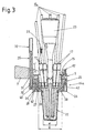
- a cup-shaped retaining ring 15 (Fig. 2, 3) Push-through holes 16 with the help of one on the retaining ring 15 in the one shown in FIGS. 3 and 4 Way, in particular in the center, attached handle button 23 can be used, in which different elongated devices, in the present case eight tubes 17, but possibly pipettes or measuring electrodes can also be used.
- the retaining ring 15 is by means of Fastening screws 15 'on the part of the device holder 5 surrounding the opening 6 screwed into a recess 5 '. 3 shows, this cup-shaped retaining ring protrudes 15 below the lower level of the device holder 5.
- the measurement signals of the measurement electrodes 17th are sent to an evaluating computer 19 (FIG. 1) via at least one cable 18, that forwards the signals from individual electrode cables 17a (FIG. 3). It understands that the measuring electrodes or tubes 17 also by other holding devices could be held in place, however, the use of a retaining ring 15 proven.
- This computer 19 possibly together with a microprocessor ⁇ controls the Sequence of a measuring program described later, which contains m in a memory and its process in a variety of ways, such as with position sensors for the respective position of the sample, washing ring 14 and / or device holder 5, but preferably as a function of time can be controlled via a clock generator 20.
- the output signal of the Microprocessor ⁇ is then a control stage 21 for the motor 13 and a control stage 21 'for the motor 13', which drives a spindle 12 '.
- a single spindle 12 or 12 ' e.g. with opposite threads for the different mentioned above and each one in the opposite To drive senses to the other acting one-way clutch. After all, one could only spindle in interaction with those that can optionally be coupled into their threads Counter threads, for example a thread that engages in a thread, can be removed Leaf spring to be provided.
- Fig. 3 shows device holder 5 and washing ring 14 in the measuring position on a sample glass 22, the contains a liquid to be titrated.
- the invention is by no means for this application limited if it is also preferably used for titration devices. It would be about possible, the moisture content of solid samples using appropriate sensors or with the help of measuring electrodes.
- a pressure pin for hardness determination about the Vickers hardness.
- the washing ring 14a differs differs from that of Fig. 1 in that the bracket arms 7 'are missing.
- the feed ring 24 is essentially parallel to the vertical direction of movement extended supply channel 29 for washing liquid connected to his Top a thickened end 30 for the connection of a leading the washing liquid hose (not shown).
- the feed channel 29 passes through a bore 31 the device holder 5 in the area of the approach of one of the bracket arms 7 (see FIG. 2).
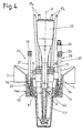
- driver part is only in FIG. 3 as driver 33 can be seen as a hint, but can clearly be seen in FIG. 4.
- the drivers 33 (at least one is provided, but is preferred) several are distributed at equal angular intervals over the respective ring) and screwed into the nozzle ring 25 on the underside.
- Conical lower stops 34 penetrate in the lower position of the device holder 5, which he during Measurement takes in complementary cone holes 35 as a stop and counter-stop on.
- the drivers 33 carry stop heads 36, which if necessary can be screwed adjustably onto a rod section 37.
- this rod section 37 the relative movement between the device holder 5 and washer 14a until either the centering cone stops 34 in the conical holes 35 penetrate and a further relative movement of the device holder 5 prevent downwards or - in the opposite direction - the stop heads 36 on the top of the cup-shaped retaining ring 15 inserted into the opening 5 ' and then take the washing ring 14a upwards. So this is a separate drive not necessary for the washing ring 14a. It is understood that the centering of the opening of the washing ring 14a to the opening 6 of the device holder 5 also differently, and in particular through separate centering pins and holes, but that in view the limited space, the use of the driver 33 especially for this purpose is cheap.
- washing nozzles 41 are therefore in a certain range Distance to the measuring electrodes inserted through the push-through opening 38 (FIG. 3) or tubes 17 and other elongate measuring probes 17 'shown in FIG. 4, so that the jet of the washing nozzles 41 expand over this distance and so one Spray larger surface area of the devices 17, 17 'summarized in the middle can.
- each, washing nozzle 41 of the washing ring 14a sits on one opening 38 penetrated by the device and its diameter d exceeding its diameter D.
- the increase in diameter from d to D also leaves the accommodation to a larger number of washing nozzles 41.
- the Nozzles 41 on the washing ring have an angular distance of at least 10 ° and less than 180 °, preferably from 15 to 20 °.
- the training is advantageously made so that at least two Wash nozzles 41 are substantially opposite one another.
- each washing nozzle 41 of the washing ring 14a is not only radially inward, but also by a predetermined angle ⁇ to the vertical axis V (the the axis of movement is also directed downwards.
- the angle ⁇ is preferably approximately 15 ° to 40 °, in particular 20 ° to 30 °. There are several reasons for this. On the one hand extended this extends the distance to the devices 17, 17 'in which the wash jet expands can The rim of the washing nozzles 41 can then be attached to a larger one Diameter D can be arranged, since the conical surface 39 also has a certain height needed to expand.
- the rim of the washing nozzles 41 already reaches one of them Height with respect to the devices 17, 17 ', in the level of which washing is no longer useful, because, as the course of the dash-dotted axis A of the washing nozzles 41 shows in FIG. 4, the wash jet reaches just below that in the push-through openings 16 Heads of devices 17, 17 ', i.e. to actually touch the sample to be tested coming shaft parts of the same.
- the slightly downward Wash jet any dirt can be solved better and driven downwards.
- the washing nozzles 41 from the inner Funnel surface 40 extend outwards from a distribution channel 42.
- This distribution channel 42 stands with the feed channel 29 according to FIG. 3 via at least one (preferably only a) Cross channel 43 in connection and leads over 360 ° around the nozzle ring 25 thus advantageously designed as an annular channel 42.
- Distribution channel 42 - starting from the opening of the cross channel 43 - in two arms to run over less than 180 ° in each case. However, this is from manufacturing Not preferred for reasons.
- the distribution channel 42 could have different cross-sectional areas over its length, since the pressure to the Nozzles 41 away from the mouth of the transverse channel 43 as a result of those arranged there first washing nozzles 41 flowing washing liquid to the opposite Washing nozzles will decrease more or less continuously.
- This pressure drop is but not significant in practice, which is why the distribution channel 42 is expediently included runs uniform cross-section over its length.
- the cross section of the distribution channel 42 is compared to that of the washing nozzles 41 relatively large in order to be able to supply a large number of washing nozzles 41. It has been shown that the average cross section of the distribution channel 42 opposite that of the nozzles 41 should be larger even if only one, for example around the Axis V rotating washer would be provided. For such a rotation of the nozzle ring 25 compared to the feed ring 24 would be the seal, which here by mere O-rings 27, 28 is given, make it more expensive, which would result in the cost of the drive.
- the ratio of the cross section of the distribution channel 42 to that of the Wash nozzles 41 at least 5: 1 and is in particular in a ratio range of 10: 1 to 50: 1. It was mentioned above why the diameter of the washing nozzles 41 advantageously at least 0.3 mm, preferably 0.5 mm and in particular 0.5 to 0.8 mm should be.
- the program memory shown in FIG. 1 m contains a program that is now - assuming it is appropriate 2 to 4, only a single, common drive motor 13 provided - to be described with reference to FIG. 5.
- the wash would be feasible in various ways, for example in the case of FIG. 1, by the device holder 5 is lowered into a sample and then moves up. The washing ring 14 could then also drive upwards while doing so and possibly in an upward and downward movement spray the devices 17, 17 'several times. However, this is preferred following procedure.
- the device holder 5 is first lowered and washer 14a together to a desired height, which by the Height of an underlying sample glass 22 is given.
- This position is in Fig. 5 b) shown.
- the desired height for the device holder 5 is - after the support of the washing ring 14a at the upper edge of the glass 22 - located somewhat lower, i.e. the Device holder moves downwards until its measuring electrodes 17 in the glass 22 and Immerse the liquid sample to be tested in it.
- This position is from Fig. 5 c) evident.
- the driver rods 33 are pushed through those shown in FIG. 4 Openings in connection to the cone openings 35 upwards.
- the feed channel 29 moves upwards in its bore 31 in the device holder 5.
- the measurement is then carried out. This is expediently from the computer 19 (Fig. 1) on the signal collecting cable 18 (Fig. 1 and 2) triggered the measurement signals from Computer registered and evaluated and finally a signal "end of measurement” issued. This signal runs over an output line 44 to the microprocessor, which Concerned about the movement of the device holder 5 and the washing ring 14a, whereas the computer 19 exclusively for the monitoring, implementation and evaluation of the Measurement is responsible. However, it is understood that both processors 19 and ⁇ in one can be executed and then the microprocessor ⁇ is part of the computer 19.
- the devices 17, 17 'move vertically relative to the washing ring 14a has the microprocessor ⁇ , controlled by the program of the program memory m, the simultaneous supply of washing liquid via the channel 29 from a not shown Washer fluid supply and via a connected to the feed channel 29 (also not shown) hose triggered.
- the glass 22 could then be removed by hand while lifting the washing ring 14a, but it is cheaper if device holder 5 and washing ring 14a according to the position of Fig. 5 b), in particular together, can be lifted into a predetermined starting position according to FIG. 5 a), so that there is more space for handling the sample glass 22.
- FIG. 6 an embodiment according to FIG. 6 with (at least) two washing rings 14 ', 14 "are provided.
- the feed channel 29 penetrates, as in the case of Fig. 3, the bore 31 of the device holder 5.
- the feed channel 29 also penetrates one narrow bore 31 'in an outer feed ring 24a, in which it with the help of two seals, how O-rings, 45, 46 are sealed.
- the feed channel 29 opens into the Feed ring 24c of the further washing ring 14 ".
- the washing rings 14 ', 14 can move relative to one another by a small amount s.
- This dimension s is due to the length of at least one, advantageously several, guide screws 47 predefined, which for adjustment may be more or less in one Screw hole 48 of an inner feed ring 24b can be screwed.
- the outer feed ring 24a screwed on As can be seen on the outside of the inner feed ring 24b is the outer feed ring 24a screwed on.
- the directions 45, 46 can be designed so that they both act against the feed channel 29 and also between the two rings 24a, 24b, otherwise, separate seals can also be provided.
- the outer feed ring 24a has, as in FIG. 3, the axially extending chamber 49, from which a radial channel 43 'leads via the distribution channel 42 to the nozzles 41'.
- the chamber 49 is connected to a radial outlet opening 50 of the feed channel 29 and is dimensioned so that this opening 50 in any relative position along the path s in the Chamber 49 opens.
- nozzles 41 "of the lower washing ring 14" in the illustrated embodiment directed obliquely upwards so that the liquid jets of the row of nozzles 41 ' and 41 "in the case of closely spaced washer rings 14 ', 14" approximately on the same or one another near neighboring locations.
- the top one Wash ring 14 ' has a taper 51 which widens towards the bottom.
- washing rings 14 ', 14 " different designs are conceivable.
- each washing ring could have a feed channel assigned only to it 29, so that, for example, each washing ring has a different washing liquid sprayed.
- the nozzle rings 41 'and 42 "could with respect to a vertical plane be offset against each other so that they are (with respect to the vertical plane) on gap. In this way, the liquid jets can be more narrow around the devices and their Outer circumference.
- it is not necessary to the two Wash jets of nozzles 41 'and nozzles 41 "against each other, and it is possibly also possible that approximately both rows of nozzles are directed downwards.
- each washer instead of a single one Wreath of nozzles 41 emanating from the distribution channel 42, also having several of them could, for example, an upper row of nozzles up, a lower row are directed downwards from nozzles.
Landscapes
- Health & Medical Sciences (AREA)
- Chemical & Material Sciences (AREA)
- Life Sciences & Earth Sciences (AREA)
- General Health & Medical Sciences (AREA)
- Analytical Chemistry (AREA)
- Biochemistry (AREA)
- Physics & Mathematics (AREA)
- General Physics & Mathematics (AREA)
- Immunology (AREA)
- Pathology (AREA)
- Clinical Laboratory Science (AREA)
- Chemical Kinetics & Catalysis (AREA)
- Molecular Biology (AREA)
- Automatic Analysis And Handling Materials Therefor (AREA)
- Cleaning By Liquid Or Steam (AREA)
Abstract
Description
- Fig. 1
- eine perspektivische Darstellung eines ersten Ausführungsbeispieles einer erfindungsgemäßen Analysenvorrichtung ohne längliche Geräte;
- Fig. 2
- eine Draufsicht auf eine bevorzugte Ausführung der erfindungsgemäßen Analysenvorrichtung im Sinne des Pfeiles II der Fig. 1 mit eingesetzten Geräten;
- Fig. 3
- einen Schnitt nach der Linie III-III der Fig. 2;
- Fig. 4
- einen Schnitt nach der Linie IV-IV der Fig. 2;
- Fig. 5
- den Bewegungsablauf zur Veranschaulichung der einzelnen Programmschritte in Schritten a), b) und c) bei einer Schnittführung durch die Vorrichtung entsprechend der Linie V-V der Fig. 2; und
- Fig. 6
- einen Schnitt ähnlich Fig. 3, jedoch eine Ausführungsvariante mit zwei Waschringen darstellend.
Claims (28)
- Analysenvorrichtung mit einer Vertikalführung (2), einem daran geführten Gerätehalter (5) und mindestens einer Wascheinrichtung für wenigstens ein vom Gerätehalter (5) gehaltenes Gerät (17, 17'), welche mindestens eine Waschdüse (41) aufweist, durch welche eine über eine Zufuhreinrichtung (24, 29, 42, 43) zugeführte Waschflüssigkeit auf das jeweilige Gerät (17, 17') sprühbar ist, dadurch gekennzeichnet, daß die Wascheinrichtung an mindestens einem vom Gerätehalter (5) gesonderten und relativ zu ihm bewegbaren, das jeweilige vom Gerätehalter (5) gehaltene Gerät (17, 17') umrundenden Waschring (14; 14a; 14', 14") mit mindestens einer gegen das jeweilige, eine Öffnung (38) des jeweiligen Waschringes (14; 14a; 14', 14") durchsetzende Gerät (17, 17') gerichteter Waschdüse (41) angeordnet ist.
- Vorrichtung nach Anspruch 1, dadurch gekennzeichnet, daß der jeweilige Waschring (14; 14a; 14', 14") über 360° verläuft und so das jeweilige, Gerät (17, 17') vollständig umgibt.
- Vorrichtung nach Anspruch 1 oder 2, dadurch gekennzeichnet, daß der jeweilige Waschring (14; 14a; 14', 14") ebenfalls an der Vertikalführung (2) geführt ist.
- Vorrichtung nach einem der vorhergehenden Ansprüche, dadurch gekennzeichnet, daß der jeweilige Waschring (14; 14a; 14', 14") unterhalb des Gerätehalters (5) angeordnet ist.
- Vorrichtung nach einem der vorhergehenden Ansprüche, dadurch gekennzeichnet, daß der jeweilige Waschring (14; 14a; 14', 14") mit mindestens zwei über seinen Umfang verteilten Waschdüsen (41) versehen ist.
- Vorrichtung nach Anspruch 5, dadurch gekennzeichnet, daß mindestens zwei Waschdüsen (41) voneinander einen im wesentlichen gleichen Winkelabstand besitzen.
- Vorrichtung nach Anspruch 5 oder 6, dadurch gekennzeichnet, daß mindestens zwei Waschdüsen (41) einander im wesentlichen gegenüberliegen.
- Vorrichtung nach einem der vorhergehenden Ansprüche, dadurch gekennzeichnet, daß die Düsen (41) am jeweiligen Waschring (14; 14a) einen Winkelabstand von mindestens 10° und weniger als 180°, vorzugsweise von 15 bis 20°, besitzen.
- Vorrichtung nach einem der vorhergehenden Ansprüche, dadurch gekennzeichnet, daß die mindestens eine Waschdüse (41) mindestens eines Waschringes (14a) an einem die vom Gerät durchsetzte Öffnung (38) übersteigenden Durchmesser (D) angeordnet ist.
- Vorrichtung nach einem der vorhergehenden Ansprüche, dadurch gekennzeichnet, daß mindestens ein Waschring (14a) eine allen Geräten (17, 17') gemeinsame Durchstecköffnung (38) besitzt.
- Vorrichtung nach einem der vorhergehenden Ansprüche, dadurch gekennzeichnet, daß die mindestens eine Waschdüse (41) des jeweiligen Waschringes (14; 14a; 14', 14") einen Mindestdurchmesser von 0,3 mm, vorzugsweise von 0,5 mm, insbesondere einen Durchmesser von 0,5 bis 0,8 mm, besitzt.
- Vorrichtung nach einem der vorhergehenden Ansprüche, dadurch gekennzeichnet, daß die mindestens eine Waschdüse (41) mindestens eines Waschringes (14; 14a; 14', 14") nicht nur radial einwärts, sondern auch um einen vorbestimmten Winkel (α) abwärts gerichtet ist.
- Vorrichtung nach Anspruch 12, dadurch gekennzeichnet, daß der vorbestimmte Winkel (α) etwa 15° bis 40°, insbesondere 20° bis 30°, beträgt.
- Vorrichtung nach einem der vorhergehenden Ansprüche, dadurch gekennzeichnet, daß der jeweilige Waschring (14; 14a; 14', 14") mit mindestens einem, seinem Umfang entlang laufenden, an die Zufuhreinrichtung (29) angeschlossenen Verteilkanal (42) für die Waschflüssigkeit versehen ist.
- Vorrichtung nach Anspruch 14, dadurch gekennzeichnet, daß der durchschnittliche Querschnitt des Verteilkanals (42) gegenüber dem der mindestens einen Düse (41) größer ist, vorzugsweise in einem Verhältnis von wenigstens 5:1, insbesondere in einem Verhältnisbereich von 10:1 bis 50:1.
- Vorrichtung nach einem der vorhergehenden Ansprüche, dadurch gekennzeichnet, daß mindestens zwei untereinander liegende Reihen von Düsen (41', 41") vorgesehen sind (Fig. 6).
- Vorrichtung nach Anspruch 16, dadurch gekennzeichnet, daß die Reihen von Düsen jeweils auf unterschiedlichen Waschringen (14', 14") angeordnet sind.
- Vorrichtung nach Anspruch 17, dadurch gekennzeichnet, daß die Waschringe (14', 14") relativ zueinander bewegbar sind.
- Vorrichtung nach einem der vorhergehenden Ansprüche, dadurch gekennzeichnet, daß die Zufuhreinrichtung einen mindestens teilweise etwa parallel zur vertikalen Bewegungsrichtung (V) erstreckten Zufuhrkanal (29) aufweist.
- Vorrichtung nach einem der vorhergehenden Ansprüche, dadurch gekennzeichnet, daß der Gerätehalter (5) Halter (15) für wenigstens zwei Geräte (17, 17') aufweist, die der jeweilige Waschring (14; 14a) gemeinsam umgibt.
- Vorrichtung nach einem der vorhergehenden Ansprüche, dadurch gekennzeichnet, daß eine Zentriereinrichtung (34, 35) zwischen Gerätehalter (5) und Waschring(en) (14a) vorgesehen ist (Fig. 4).
- Vorrichtung nach einem der vorhergehenden Ansprüche, dadurch gekennzeichnet, daß der Gerätehalter (5) mittels eines Antriebes (12, 13) entlang der Vertikalführung (2) bewegbar ist, und daß der jeweilige Waschring (14; 14a) vorzugsweise mittels desselben Antriebes (12, 13) vertikal bewegbar ist.
- Vorrichtung nach Anspruch 22, dadurch gekennzeichnet, daß Gerätehalter (5) und Waschring(e) (14; 14a) untereinander durch wenigstens einen eine Relativbewegung zulassenden Mitnehmer (33) verbunden sind.
- Antriebsvorrichtung, insbesondere für eine Vorrichtung nach einem der vorhergehenden Ansprüche, dadurch gekennzeichnet, daß sie mindestens einen von einer Programmsteuereinrichtung (m, µ) gesteuerten Motor (13, 13')aufweist.
- Vorrichtung nach Anspruch 24, dadurch gekennzeichnet, daß die Programmsteuereinrichtung (m, µ) einen Programmspeicher (m) für die Durchführung wenigstens folgender Schritte aufweist:a) Absenken von Gerätehalter (5) und Waschring (14; 14a; 14', 14") bis zu einer jeweils gewünschten Höhe;b) Durchführung der Messung;c) vertikales Relativbewegen des mindestens einen Gerätes (17, 17') am Gerätehalter (5) gegenüber dem Waschring (14; 14a; 14', 14") bei gleichzeitiger Zuführung von Waschflüssigkeit.
- Vorrichtung nach Anspruch 25, dadurch gekennzeichnet, daß ein Meßwertaufnehmer, z.B. ein Speicher, ein Computer (19) oder Prozessor, vorgesehen ist, der den Abschluß der Messung überwacht und nach Durchführung des Schrittes b) ein Signal zur Auslösung des Schrittes c) abgibt.
- Vorrichtung nach Anspruch 25 oder 26, dadurch gekennzeichnet, daß im Schritt
a) der Waschring (14; 14a; 14', 14") bis zu einer ersten vorbestimmten Höhe führbar ist, wogegen sich der Gerätehalter (5) bis zu einer zweiten vorbestimmten Höhe absenkt. - Vorrichtung nach einem der Ansprüche 25 bis 27, dadurch gekennzeichnet, daß Gerätehalter (5) und Waschring (14; 14a; 14', 14") nach dem Schritt c), insbesondere gemeinsam, in eine vorbestimmte Ausgangslage hebbar sind (Fig. 5a)).
Applications Claiming Priority (2)
| Application Number | Priority Date | Filing Date | Title |
|---|---|---|---|
| DE10001895A DE10001895A1 (de) | 2000-01-19 | 2000-01-19 | Analysenvorrichtung und Antriebsvorrichtung hierfür |
| DE10001895 | 2000-01-19 |
Publications (3)
| Publication Number | Publication Date |
|---|---|
| EP1118861A2 true EP1118861A2 (de) | 2001-07-25 |
| EP1118861A3 EP1118861A3 (de) | 2004-01-14 |
| EP1118861B1 EP1118861B1 (de) | 2005-08-10 |
Family
ID=7627869
Family Applications (1)
| Application Number | Title | Priority Date | Filing Date |
|---|---|---|---|
| EP01100717A Expired - Lifetime EP1118861B1 (de) | 2000-01-19 | 2001-01-12 | Analysenvorrichtung mit vertikal bewegbarer Wascheinrichtung |
Country Status (5)
| Country | Link |
|---|---|
| US (1) | US7862774B2 (de) |
| EP (1) | EP1118861B1 (de) |
| JP (1) | JP2001249138A (de) |
| AT (1) | ATE301498T1 (de) |
| DE (2) | DE10001895A1 (de) |
Cited By (1)
| Publication number | Priority date | Publication date | Assignee | Title |
|---|---|---|---|---|
| WO2006121789A3 (en) * | 2005-05-06 | 2007-01-25 | Instrumentation Lab Co | Telescoping closed-tube sampling assembly |
Families Citing this family (7)
| Publication number | Priority date | Publication date | Assignee | Title |
|---|---|---|---|---|
| US20080099057A1 (en) * | 2006-10-27 | 2008-05-01 | Dade Behring Inc. | Method and Device for Cleaning a Liquid Aspiration and Dispense Probe |
| GB201101872D0 (en) * | 2011-02-03 | 2011-03-23 | Majeed Ali W | Instrument cleaning assembly and apparatus |
| JP5850786B2 (ja) * | 2012-04-04 | 2016-02-03 | 京都電子工業株式会社 | 自動滴定装置 |
| CN104487819B (zh) * | 2012-06-22 | 2017-10-27 | 生物辐射实验室股份有限公司 | 两站式样本及洗涤系统 |
| EP3133401A1 (de) * | 2015-08-18 | 2017-02-22 | Siemens Healthcare Diagnostics Products GmbH | Verfahren zur reinigung einer pipettiernadel in einem automatischen analysegerät |
| US10697881B2 (en) | 2016-02-18 | 2020-06-30 | Bio-Rad Laboratories, Inc. | Crash protected sampler for flow cytometer |
| CN117451924B (zh) * | 2023-12-26 | 2024-03-15 | 山东煜可医疗科技有限公司 | 一种药品检验用分析滴定装置 |
Family Cites Families (18)
| Publication number | Priority date | Publication date | Assignee | Title |
|---|---|---|---|---|
| US3266322A (en) * | 1964-06-15 | 1966-08-16 | Technicon Instr | Automatic liquid sample supply and wash apparatus for automatic analysis system |
| SE336241B (de) * | 1967-12-06 | 1971-06-28 | Linson Instr Ab | |
| AT354162B (de) * | 1977-06-13 | 1979-12-27 | Waagner Biro Ag | Einrichtung zur selbsttaetigen reinigung von messelektroden |
| US4318885A (en) * | 1979-09-10 | 1982-03-09 | Olympus Optical Co., Ltd. | Liquid treating device for chemical analysis apparatus |
| US4338280A (en) * | 1981-04-02 | 1982-07-06 | Instrumentation Laboratory Inc. | Fluid sampling |
| DE3405234A1 (de) * | 1984-02-15 | 1985-08-29 | Friedrich Wilhelm Dipl.-Ing. 6100 Darmstadt Siepmann | Verfahren und vorrichtung zum reinigen einer umstroemten membran |
| DE3405962A1 (de) * | 1984-02-18 | 1985-08-22 | Dieter van 2808 Syke Züren | Sonde zur fuellstandsmessung |
| GR871619B (en) * | 1986-10-31 | 1988-03-03 | Genetic Systems Corp | Automated patient sample analysis instrument |
| JPH0640100B2 (ja) * | 1987-11-27 | 1994-05-25 | 株式会社日立製作所 | 自動分析装置のサンプル分注方法 |
| US5408891A (en) * | 1992-12-17 | 1995-04-25 | Beckman Instruments, Inc. | Fluid probe washing apparatus and method |
| CA2167471A1 (en) * | 1995-01-31 | 1996-08-01 | Johnson & Johnson Clinical Diagnostics, Inc. | Probe wash device |
| DE19511037C2 (de) * | 1995-03-28 | 1997-05-07 | Karl Schad | Verfahren und Gerät zum Reinigen und/oder Desinfizieren von chirurgischen Instrumenten |
| JPH08338849A (ja) * | 1995-04-11 | 1996-12-24 | Precision Syst Sci Kk | 液体の吸引判別方法およびこの方法により駆動制御される分注装置 |
| DE19610607A1 (de) * | 1996-03-18 | 1997-09-25 | Boehringer Mannheim Gmbh | Vorrichtung zur Reinigung von Pipettiernadeln oder Rührern |
| JP3572792B2 (ja) * | 1996-04-04 | 2004-10-06 | 東ソー株式会社 | 前処理装置 |
| JP3448436B2 (ja) * | 1996-08-21 | 2003-09-22 | 日本電子株式会社 | 生化学自動分析装置における洗浄装置 |
| DE10018876A1 (de) * | 2000-04-14 | 2001-10-25 | Mettler Toledo Gmbh | Analysenvorrichtung und Analysiereinrichtung |
| DE10241834A1 (de) * | 2002-09-09 | 2004-03-25 | Mettler-Toledo Gmbh | Spülvorrichtung für einen Sensor |
-
2000
- 2000-01-19 DE DE10001895A patent/DE10001895A1/de not_active Withdrawn
-
2001
- 2001-01-12 AT AT01100717T patent/ATE301498T1/de not_active IP Right Cessation
- 2001-01-12 DE DE50107006T patent/DE50107006D1/de not_active Expired - Lifetime
- 2001-01-12 EP EP01100717A patent/EP1118861B1/de not_active Expired - Lifetime
- 2001-01-18 US US09/765,112 patent/US7862774B2/en active Active
- 2001-01-18 JP JP2001010502A patent/JP2001249138A/ja active Pending
Cited By (3)
| Publication number | Priority date | Publication date | Assignee | Title |
|---|---|---|---|---|
| WO2006121789A3 (en) * | 2005-05-06 | 2007-01-25 | Instrumentation Lab Co | Telescoping closed-tube sampling assembly |
| US8758702B2 (en) | 2005-05-06 | 2014-06-24 | Instrumentation Laboratory Company | Telescoping closed-tube sampling assembly |
| US9817010B2 (en) | 2005-05-06 | 2017-11-14 | Instrumentation Laboratory Company | Telescoping closed-tube sampling assembly |
Also Published As
| Publication number | Publication date |
|---|---|
| ATE301498T1 (de) | 2005-08-15 |
| EP1118861B1 (de) | 2005-08-10 |
| US20010021354A1 (en) | 2001-09-13 |
| EP1118861A3 (de) | 2004-01-14 |
| US7862774B2 (en) | 2011-01-04 |
| DE50107006D1 (de) | 2005-09-15 |
| DE10001895A1 (de) | 2001-07-26 |
| JP2001249138A (ja) | 2001-09-14 |
Similar Documents
| Publication | Publication Date | Title |
|---|---|---|
| EP0888553B1 (de) | Vorrichtung zur reinigung von pipettiernadeln oder rührern | |
| DE2947608C2 (de) | Gerät zum Abreinigen eines Endoskopes | |
| EP0416371B1 (de) | Endoskopoptik | |
| EP2693188B1 (de) | Festphasenmikroextraktion | |
| EP1118861B1 (de) | Analysenvorrichtung mit vertikal bewegbarer Wascheinrichtung | |
| EP3112859B1 (de) | Probenhalter einer analyseeinrichtung für die elementaranalyse und analyseeinrichtung für die elementaranalyse | |
| EP1354211A1 (de) | Pipettiervorrichtung | |
| DE8218000U1 (de) | Vorrichtung zum waschen von gemuese, fruechten oder aehnlichen produkten | |
| DE60225968T2 (de) | Vorrichtung und Verfahren zur Bereitstellung von Bodenproben | |
| DE2754636A1 (de) | Reinigungsvorrichtung fuer werkzeugspannkegel | |
| EP0589363B1 (de) | Verfahren und Vorrichtung zum berührungslosen automatischen Mischen eines Reaktionsgemisches in enem Analysegerät | |
| DE3634137A1 (de) | Verfahren und vorrichtung zum diskontinuierlichen aufbringen eines aushaertenden stoffes auf einen gegenstand | |
| EP2034300B1 (de) | Vorrichtung zur Messung eines Strömungspotentials | |
| DE202006008820U1 (de) | Homogenisator-Vorrichtung mit horizotal gelagerten Zahnkränzen | |
| EP0367917A2 (de) | Vorrichtung zur wahlweisen Durchführung von Wasserpunktur oder Hydro-Ionisation | |
| EP2347268B1 (de) | Automatisierte analysevorrichtung mit einer automatischen pipettiervorrichtung und mit einer pipettiernadelspülstation | |
| DE2550617B2 (de) | Vorrichtung zur Herstellung von metallenen Ringrohlingen | |
| EP0521475A2 (de) | Füllelement | |
| DE2707231B2 (de) | Halter für Küvetten | |
| DE10008982A1 (de) | Vorrichtung zum Reinigen von Behältern | |
| DE2304768C2 (de) | Aufsatz für Reaktionskolben | |
| DE102007043094B4 (de) | Vorrichtung zur Messung eines Strömungspotentials | |
| DE377117C (de) | Presse zum Zusammensetzen von Knoepfen | |
| DE3315868C2 (de) | Vorrichtung zum Reinigen von scheibenförmingen Analysencuvetten | |
| DE2247107A1 (de) | Vorrichtung und verfahren zur herstellung von gradienten |
Legal Events
| Date | Code | Title | Description |
|---|---|---|---|
| PUAI | Public reference made under article 153(3) epc to a published international application that has entered the european phase |
Free format text: ORIGINAL CODE: 0009012 |
|
| AK | Designated contracting states |
Kind code of ref document: A2 Designated state(s): AT BE CH CY DE DK ES FI FR GB GR IE IT LI LU MC NL PT SE TR |
|
| AX | Request for extension of the european patent |
Free format text: AL;LT;LV;MK;RO;SI |
|
| PUAL | Search report despatched |
Free format text: ORIGINAL CODE: 0009013 |
|
| AK | Designated contracting states |
Kind code of ref document: A3 Designated state(s): AT BE CH CY DE DK ES FI FR GB GR IE IT LI LU MC NL PT SE TR |
|
| AX | Request for extension of the european patent |
Extension state: AL LT LV MK RO SI |
|
| RIC1 | Information provided on ipc code assigned before grant |
Ipc: 7B 01L 11/00 A Ipc: 7G 01N 35/10 B |
|
| 17P | Request for examination filed |
Effective date: 20040713 |
|
| AKX | Designation fees paid |
Designated state(s): AT BE CH CY DE DK ES FI FR GB GR IE IT LI LU MC NL PT SE TR |
|
| 17Q | First examination report despatched |
Effective date: 20040928 |
|
| GRAP | Despatch of communication of intention to grant a patent |
Free format text: ORIGINAL CODE: EPIDOSNIGR1 |
|
| GRAJ | Information related to disapproval of communication of intention to grant by the applicant or resumption of examination proceedings by the epo deleted |
Free format text: ORIGINAL CODE: EPIDOSDIGR1 |
|
| GRAP | Despatch of communication of intention to grant a patent |
Free format text: ORIGINAL CODE: EPIDOSNIGR1 |
|
| RTI1 | Title (correction) |
Free format text: ANALYSIS DEVICE WITH VERTICALLY MOVABLE WASHING APPARATUS |
|
| GRAS | Grant fee paid |
Free format text: ORIGINAL CODE: EPIDOSNIGR3 |
|
| GRAA | (expected) grant |
Free format text: ORIGINAL CODE: 0009210 |
|
| AK | Designated contracting states |
Kind code of ref document: B1 Designated state(s): AT BE CH CY DE DK ES FI FR GB GR IE IT LI LU MC NL PT SE TR |
|
| PG25 | Lapsed in a contracting state [announced via postgrant information from national office to epo] |
Ref country code: IT Free format text: LAPSE BECAUSE OF FAILURE TO SUBMIT A TRANSLATION OF THE DESCRIPTION OR TO PAY THE FEE WITHIN THE PRESCRIBED TIME-LIMIT;WARNING: LAPSES OF ITALIAN PATENTS WITH EFFECTIVE DATE BEFORE 2007 MAY HAVE OCCURRED AT ANY TIME BEFORE 2007. THE CORRECT EFFECTIVE DATE MAY BE DIFFERENT FROM THE ONE RECORDED. Effective date: 20050810 Ref country code: FI Free format text: LAPSE BECAUSE OF FAILURE TO SUBMIT A TRANSLATION OF THE DESCRIPTION OR TO PAY THE FEE WITHIN THE PRESCRIBED TIME-LIMIT Effective date: 20050810 Ref country code: IE Free format text: LAPSE BECAUSE OF FAILURE TO SUBMIT A TRANSLATION OF THE DESCRIPTION OR TO PAY THE FEE WITHIN THE PRESCRIBED TIME-LIMIT Effective date: 20050810 Ref country code: NL Free format text: LAPSE BECAUSE OF FAILURE TO SUBMIT A TRANSLATION OF THE DESCRIPTION OR TO PAY THE FEE WITHIN THE PRESCRIBED TIME-LIMIT Effective date: 20050810 Ref country code: TR Free format text: LAPSE BECAUSE OF FAILURE TO SUBMIT A TRANSLATION OF THE DESCRIPTION OR TO PAY THE FEE WITHIN THE PRESCRIBED TIME-LIMIT Effective date: 20050810 |
|
| REG | Reference to a national code |
Ref country code: GB Ref legal event code: FG4D Free format text: NOT ENGLISH |
|
| REG | Reference to a national code |
Ref country code: CH Ref legal event code: EP |
|
| REG | Reference to a national code |
Ref country code: IE Ref legal event code: FG4D Free format text: LANGUAGE OF EP DOCUMENT: GERMAN |
|
| REF | Corresponds to: |
Ref document number: 50107006 Country of ref document: DE Date of ref document: 20050915 Kind code of ref document: P |
|
| PG25 | Lapsed in a contracting state [announced via postgrant information from national office to epo] |
Ref country code: DK Free format text: LAPSE BECAUSE OF FAILURE TO SUBMIT A TRANSLATION OF THE DESCRIPTION OR TO PAY THE FEE WITHIN THE PRESCRIBED TIME-LIMIT Effective date: 20051110 Ref country code: SE Free format text: LAPSE BECAUSE OF FAILURE TO SUBMIT A TRANSLATION OF THE DESCRIPTION OR TO PAY THE FEE WITHIN THE PRESCRIBED TIME-LIMIT Effective date: 20051110 Ref country code: GR Free format text: LAPSE BECAUSE OF FAILURE TO SUBMIT A TRANSLATION OF THE DESCRIPTION OR TO PAY THE FEE WITHIN THE PRESCRIBED TIME-LIMIT Effective date: 20051110 |
|
| GBT | Gb: translation of ep patent filed (gb section 77(6)(a)/1977) |
Effective date: 20051021 |
|
| PG25 | Lapsed in a contracting state [announced via postgrant information from national office to epo] |
Ref country code: ES Free format text: LAPSE BECAUSE OF FAILURE TO SUBMIT A TRANSLATION OF THE DESCRIPTION OR TO PAY THE FEE WITHIN THE PRESCRIBED TIME-LIMIT Effective date: 20051121 |
|
| PG25 | Lapsed in a contracting state [announced via postgrant information from national office to epo] |
Ref country code: PT Free format text: LAPSE BECAUSE OF FAILURE TO SUBMIT A TRANSLATION OF THE DESCRIPTION OR TO PAY THE FEE WITHIN THE PRESCRIBED TIME-LIMIT Effective date: 20060110 |
|
| PG25 | Lapsed in a contracting state [announced via postgrant information from national office to epo] |
Ref country code: AT Free format text: LAPSE BECAUSE OF NON-PAYMENT OF DUE FEES Effective date: 20060112 |
|
| PG25 | Lapsed in a contracting state [announced via postgrant information from national office to epo] |
Ref country code: LU Free format text: LAPSE BECAUSE OF NON-PAYMENT OF DUE FEES Effective date: 20060131 Ref country code: BE Free format text: LAPSE BECAUSE OF NON-PAYMENT OF DUE FEES Effective date: 20060131 Ref country code: MC Free format text: LAPSE BECAUSE OF NON-PAYMENT OF DUE FEES Effective date: 20060131 |
|
| NLV1 | Nl: lapsed or annulled due to failure to fulfill the requirements of art. 29p and 29m of the patents act | ||
| REG | Reference to a national code |
Ref country code: IE Ref legal event code: FD4D |
|
| ET | Fr: translation filed | ||
| PLBE | No opposition filed within time limit |
Free format text: ORIGINAL CODE: 0009261 |
|
| STAA | Information on the status of an ep patent application or granted ep patent |
Free format text: STATUS: NO OPPOSITION FILED WITHIN TIME LIMIT |
|
| 26N | No opposition filed |
Effective date: 20060511 |
|
| REG | Reference to a national code |
Ref country code: CH Ref legal event code: PFA Owner name: METTLER-TOLEDO AG Free format text: METTLER-TOLEDO GMBH#IM LANGACHER#8606 GREIFENSEE (CH) -TRANSFER TO- METTLER-TOLEDO AG#IM LANGACHER#8606 GREIFENSEE (CH) |
|
| REG | Reference to a national code |
Ref country code: FR Ref legal event code: CD Ref country code: FR Ref legal event code: CJ |
|
| BERE | Be: lapsed |
Owner name: METTLER-TOLEDO GMBH Effective date: 20060131 |
|
| PG25 | Lapsed in a contracting state [announced via postgrant information from national office to epo] |
Ref country code: CY Free format text: LAPSE BECAUSE OF FAILURE TO SUBMIT A TRANSLATION OF THE DESCRIPTION OR TO PAY THE FEE WITHIN THE PRESCRIBED TIME-LIMIT Effective date: 20050810 |
|
| REG | Reference to a national code |
Ref country code: CH Ref legal event code: PCOW Free format text: NEW ADDRESS: IM LANGACHER 44, 8606 GREIFENSEE (CH) |
|
| REG | Reference to a national code |
Ref country code: FR Ref legal event code: PLFP Year of fee payment: 16 |
|
| REG | Reference to a national code |
Ref country code: CH Ref legal event code: PFA Owner name: METTLER-TOLEDO GMBH, CH Free format text: FORMER OWNER: METTLER-TOLEDO AG, CH |
|
| REG | Reference to a national code |
Ref country code: FR Ref legal event code: PLFP Year of fee payment: 17 |
|
| PGFP | Annual fee paid to national office [announced via postgrant information from national office to epo] |
Ref country code: GB Payment date: 20161228 Year of fee payment: 17 |
|
| PGFP | Annual fee paid to national office [announced via postgrant information from national office to epo] |
Ref country code: FR Payment date: 20170103 Year of fee payment: 17 |
|
| REG | Reference to a national code |
Ref country code: DE Ref legal event code: R082 Ref document number: 50107006 Country of ref document: DE Representative=s name: LEINWEBER & ZIMMERMANN PATENTANWALTS-PARTG MBB, DE Ref country code: DE Ref legal event code: R082 Ref document number: 50107006 Country of ref document: DE Representative=s name: LEINWEBER & ZIMMERMANN, DE Ref country code: DE Ref legal event code: R081 Ref document number: 50107006 Country of ref document: DE Owner name: METTLER-TOLEDO GMBH, CH Free format text: FORMER OWNER: METTLER-TOLEDO AG, GREIFENSEE, CH |
|
| REG | Reference to a national code |
Ref country code: FR Ref legal event code: CJ Effective date: 20180409 |
|
| GBPC | Gb: european patent ceased through non-payment of renewal fee |
Effective date: 20180112 |
|
| PG25 | Lapsed in a contracting state [announced via postgrant information from national office to epo] |
Ref country code: FR Free format text: LAPSE BECAUSE OF NON-PAYMENT OF DUE FEES Effective date: 20180131 |
|
| REG | Reference to a national code |
Ref country code: FR Ref legal event code: ST Effective date: 20180928 |
|
| PG25 | Lapsed in a contracting state [announced via postgrant information from national office to epo] |
Ref country code: GB Free format text: LAPSE BECAUSE OF NON-PAYMENT OF DUE FEES Effective date: 20180112 |
|
| PGFP | Annual fee paid to national office [announced via postgrant information from national office to epo] |
Ref country code: DE Payment date: 20191218 Year of fee payment: 20 |
|
| PGFP | Annual fee paid to national office [announced via postgrant information from national office to epo] |
Ref country code: CH Payment date: 20200106 Year of fee payment: 20 |
|
| REG | Reference to a national code |
Ref country code: DE Ref legal event code: R071 Ref document number: 50107006 Country of ref document: DE |
|
| REG | Reference to a national code |
Ref country code: CH Ref legal event code: PL |