EP3112859B1 - Probenhalter einer analyseeinrichtung für die elementaranalyse und analyseeinrichtung für die elementaranalyse - Google Patents
Probenhalter einer analyseeinrichtung für die elementaranalyse und analyseeinrichtung für die elementaranalyse Download PDFInfo
- Publication number
- EP3112859B1 EP3112859B1 EP16175981.6A EP16175981A EP3112859B1 EP 3112859 B1 EP3112859 B1 EP 3112859B1 EP 16175981 A EP16175981 A EP 16175981A EP 3112859 B1 EP3112859 B1 EP 3112859B1
- Authority
- EP
- European Patent Office
- Prior art keywords
- plate
- hole
- perforated
- sample
- field plate
- Prior art date
- Legal status (The legal status is an assumption and is not a legal conclusion. Google has not performed a legal analysis and makes no representation as to the accuracy of the status listed.)
- Active
Links
- 238000000921 elemental analysis Methods 0.000 title description 9
- 238000004458 analytical method Methods 0.000 claims description 19
- 238000007084 catalytic combustion reaction Methods 0.000 claims description 8
- 239000011261 inert gas Substances 0.000 claims description 7
- QVGXLLKOCUKJST-UHFFFAOYSA-N atomic oxygen Chemical compound [O] QVGXLLKOCUKJST-UHFFFAOYSA-N 0.000 claims description 6
- 239000001301 oxygen Substances 0.000 claims description 6
- 229910052760 oxygen Inorganic materials 0.000 claims description 6
- 238000007789 sealing Methods 0.000 claims description 2
- 239000007789 gas Substances 0.000 description 10
- IJGRMHOSHXDMSA-UHFFFAOYSA-N Atomic nitrogen Chemical compound N#N IJGRMHOSHXDMSA-UHFFFAOYSA-N 0.000 description 6
- XLYOFNOQVPJJNP-UHFFFAOYSA-N water Substances O XLYOFNOQVPJJNP-UHFFFAOYSA-N 0.000 description 5
- 239000012080 ambient air Substances 0.000 description 3
- 239000000567 combustion gas Substances 0.000 description 3
- 229910052757 nitrogen Inorganic materials 0.000 description 3
- 230000008929 regeneration Effects 0.000 description 3
- 238000011069 regeneration method Methods 0.000 description 3
- CURLTUGMZLYLDI-UHFFFAOYSA-N Carbon dioxide Chemical compound O=C=O CURLTUGMZLYLDI-UHFFFAOYSA-N 0.000 description 2
- 241000698776 Duma Species 0.000 description 2
- 238000003795 desorption Methods 0.000 description 2
- 230000018109 developmental process Effects 0.000 description 2
- 230000005484 gravity Effects 0.000 description 2
- 239000001307 helium Substances 0.000 description 2
- 229910052734 helium Inorganic materials 0.000 description 2
- SWQJXJOGLNCZEY-UHFFFAOYSA-N helium atom Chemical compound [He] SWQJXJOGLNCZEY-UHFFFAOYSA-N 0.000 description 2
- MYMOFIZGZYHOMD-UHFFFAOYSA-N Dioxygen Chemical compound O=O MYMOFIZGZYHOMD-UHFFFAOYSA-N 0.000 description 1
- 239000006096 absorbing agent Substances 0.000 description 1
- 239000003570 air Substances 0.000 description 1
- 230000015572 biosynthetic process Effects 0.000 description 1
- 229910002092 carbon dioxide Inorganic materials 0.000 description 1
- 239000001569 carbon dioxide Substances 0.000 description 1
- 238000002485 combustion reaction Methods 0.000 description 1
- 229910001882 dioxygen Inorganic materials 0.000 description 1
- 238000007599 discharging Methods 0.000 description 1
- 230000000694 effects Effects 0.000 description 1
- 239000004615 ingredient Substances 0.000 description 1
- 230000001404 mediated effect Effects 0.000 description 1
- 230000002093 peripheral effect Effects 0.000 description 1
- 238000000926 separation method Methods 0.000 description 1
- 239000000126 substance Substances 0.000 description 1
- 239000000758 substrate Substances 0.000 description 1
Images


Classifications
-
- G—PHYSICS
- G01—MEASURING; TESTING
- G01N—INVESTIGATING OR ANALYSING MATERIALS BY DETERMINING THEIR CHEMICAL OR PHYSICAL PROPERTIES
- G01N31/00—Investigating or analysing non-biological materials by the use of the chemical methods specified in the subgroup; Apparatus specially adapted for such methods
- G01N31/12—Investigating or analysing non-biological materials by the use of the chemical methods specified in the subgroup; Apparatus specially adapted for such methods using combustion
-
- G—PHYSICS
- G01—MEASURING; TESTING
- G01N—INVESTIGATING OR ANALYSING MATERIALS BY DETERMINING THEIR CHEMICAL OR PHYSICAL PROPERTIES
- G01N25/00—Investigating or analyzing materials by the use of thermal means
- G01N25/20—Investigating or analyzing materials by the use of thermal means by investigating the development of heat, i.e. calorimetry, e.g. by measuring specific heat, by measuring thermal conductivity
- G01N25/22—Investigating or analyzing materials by the use of thermal means by investigating the development of heat, i.e. calorimetry, e.g. by measuring specific heat, by measuring thermal conductivity on combustion or catalytic oxidation, e.g. of components of gas mixtures
-
- B—PERFORMING OPERATIONS; TRANSPORTING
- B01—PHYSICAL OR CHEMICAL PROCESSES OR APPARATUS IN GENERAL
- B01L—CHEMICAL OR PHYSICAL LABORATORY APPARATUS FOR GENERAL USE
- B01L3/00—Containers or dishes for laboratory use, e.g. laboratory glassware; Droppers
- B01L3/50—Containers for the purpose of retaining a material to be analysed, e.g. test tubes
- B01L3/502—Containers for the purpose of retaining a material to be analysed, e.g. test tubes with fluid transport, e.g. in multi-compartment structures
-
- B—PERFORMING OPERATIONS; TRANSPORTING
- B01—PHYSICAL OR CHEMICAL PROCESSES OR APPARATUS IN GENERAL
- B01L—CHEMICAL OR PHYSICAL LABORATORY APPARATUS FOR GENERAL USE
- B01L3/00—Containers or dishes for laboratory use, e.g. laboratory glassware; Droppers
- B01L3/50—Containers for the purpose of retaining a material to be analysed, e.g. test tubes
- B01L3/508—Containers for the purpose of retaining a material to be analysed, e.g. test tubes rigid containers not provided for above
- B01L3/5085—Containers for the purpose of retaining a material to be analysed, e.g. test tubes rigid containers not provided for above for multiple samples, e.g. microtitration plates
-
- G—PHYSICS
- G01—MEASURING; TESTING
- G01N—INVESTIGATING OR ANALYSING MATERIALS BY DETERMINING THEIR CHEMICAL OR PHYSICAL PROPERTIES
- G01N35/00—Automatic analysis not limited to methods or materials provided for in any single one of groups G01N1/00 - G01N33/00; Handling materials therefor
- G01N35/00029—Automatic analysis not limited to methods or materials provided for in any single one of groups G01N1/00 - G01N33/00; Handling materials therefor provided with flat sample substrates, e.g. slides
-
- G—PHYSICS
- G01—MEASURING; TESTING
- G01N—INVESTIGATING OR ANALYSING MATERIALS BY DETERMINING THEIR CHEMICAL OR PHYSICAL PROPERTIES
- G01N35/00—Automatic analysis not limited to methods or materials provided for in any single one of groups G01N1/00 - G01N33/00; Handling materials therefor
- G01N35/00584—Control arrangements for automatic analysers
- G01N35/00722—Communications; Identification
-
- G—PHYSICS
- G01—MEASURING; TESTING
- G01N—INVESTIGATING OR ANALYSING MATERIALS BY DETERMINING THEIR CHEMICAL OR PHYSICAL PROPERTIES
- G01N35/00—Automatic analysis not limited to methods or materials provided for in any single one of groups G01N1/00 - G01N33/00; Handling materials therefor
- G01N35/02—Automatic analysis not limited to methods or materials provided for in any single one of groups G01N1/00 - G01N33/00; Handling materials therefor using a plurality of sample containers moved by a conveyor system past one or more treatment or analysis stations
- G01N35/026—Automatic analysis not limited to methods or materials provided for in any single one of groups G01N1/00 - G01N33/00; Handling materials therefor using a plurality of sample containers moved by a conveyor system past one or more treatment or analysis stations having blocks or racks of reaction cells or cuvettes
-
- G—PHYSICS
- G01—MEASURING; TESTING
- G01N—INVESTIGATING OR ANALYSING MATERIALS BY DETERMINING THEIR CHEMICAL OR PHYSICAL PROPERTIES
- G01N35/00—Automatic analysis not limited to methods or materials provided for in any single one of groups G01N1/00 - G01N33/00; Handling materials therefor
- G01N35/02—Automatic analysis not limited to methods or materials provided for in any single one of groups G01N1/00 - G01N33/00; Handling materials therefor using a plurality of sample containers moved by a conveyor system past one or more treatment or analysis stations
- G01N35/04—Details of the conveyor system
-
- G—PHYSICS
- G01—MEASURING; TESTING
- G01N—INVESTIGATING OR ANALYSING MATERIALS BY DETERMINING THEIR CHEMICAL OR PHYSICAL PROPERTIES
- G01N35/00—Automatic analysis not limited to methods or materials provided for in any single one of groups G01N1/00 - G01N33/00; Handling materials therefor
- G01N35/10—Devices for transferring samples or any liquids to, in, or from, the analysis apparatus, e.g. suction devices, injection devices
- G01N35/1081—Devices for transferring samples or any liquids to, in, or from, the analysis apparatus, e.g. suction devices, injection devices characterised by the means for relatively moving the transfer device and the containers in an horizontal plane
- G01N35/109—Devices for transferring samples or any liquids to, in, or from, the analysis apparatus, e.g. suction devices, injection devices characterised by the means for relatively moving the transfer device and the containers in an horizontal plane with two horizontal degrees of freedom
-
- B—PERFORMING OPERATIONS; TRANSPORTING
- B01—PHYSICAL OR CHEMICAL PROCESSES OR APPARATUS IN GENERAL
- B01L—CHEMICAL OR PHYSICAL LABORATORY APPARATUS FOR GENERAL USE
- B01L2200/00—Solutions for specific problems relating to chemical or physical laboratory apparatus
- B01L2200/02—Adapting objects or devices to another
- B01L2200/025—Align devices or objects to ensure defined positions relative to each other
-
- B—PERFORMING OPERATIONS; TRANSPORTING
- B01—PHYSICAL OR CHEMICAL PROCESSES OR APPARATUS IN GENERAL
- B01L—CHEMICAL OR PHYSICAL LABORATORY APPARATUS FOR GENERAL USE
- B01L2200/00—Solutions for specific problems relating to chemical or physical laboratory apparatus
- B01L2200/02—Adapting objects or devices to another
- B01L2200/026—Fluid interfacing between devices or objects, e.g. connectors, inlet details
-
- B—PERFORMING OPERATIONS; TRANSPORTING
- B01—PHYSICAL OR CHEMICAL PROCESSES OR APPARATUS IN GENERAL
- B01L—CHEMICAL OR PHYSICAL LABORATORY APPARATUS FOR GENERAL USE
- B01L2200/00—Solutions for specific problems relating to chemical or physical laboratory apparatus
- B01L2200/14—Process control and prevention of errors
-
- B—PERFORMING OPERATIONS; TRANSPORTING
- B01—PHYSICAL OR CHEMICAL PROCESSES OR APPARATUS IN GENERAL
- B01L—CHEMICAL OR PHYSICAL LABORATORY APPARATUS FOR GENERAL USE
- B01L2300/00—Additional constructional details
- B01L2300/06—Auxiliary integrated devices, integrated components
- B01L2300/0627—Sensor or part of a sensor is integrated
-
- B—PERFORMING OPERATIONS; TRANSPORTING
- B01—PHYSICAL OR CHEMICAL PROCESSES OR APPARATUS IN GENERAL
- B01L—CHEMICAL OR PHYSICAL LABORATORY APPARATUS FOR GENERAL USE
- B01L2300/00—Additional constructional details
- B01L2300/06—Auxiliary integrated devices, integrated components
- B01L2300/069—Absorbents; Gels to retain a fluid
-
- B—PERFORMING OPERATIONS; TRANSPORTING
- B01—PHYSICAL OR CHEMICAL PROCESSES OR APPARATUS IN GENERAL
- B01L—CHEMICAL OR PHYSICAL LABORATORY APPARATUS FOR GENERAL USE
- B01L2300/00—Additional constructional details
- B01L2300/08—Geometry, shape and general structure
- B01L2300/0809—Geometry, shape and general structure rectangular shaped
-
- G—PHYSICS
- G01—MEASURING; TESTING
- G01N—INVESTIGATING OR ANALYSING MATERIALS BY DETERMINING THEIR CHEMICAL OR PHYSICAL PROPERTIES
- G01N35/00—Automatic analysis not limited to methods or materials provided for in any single one of groups G01N1/00 - G01N33/00; Handling materials therefor
- G01N35/00029—Automatic analysis not limited to methods or materials provided for in any single one of groups G01N1/00 - G01N33/00; Handling materials therefor provided with flat sample substrates, e.g. slides
- G01N2035/00099—Characterised by type of test elements
-
- G—PHYSICS
- G01—MEASURING; TESTING
- G01N—INVESTIGATING OR ANALYSING MATERIALS BY DETERMINING THEIR CHEMICAL OR PHYSICAL PROPERTIES
- G01N35/00—Automatic analysis not limited to methods or materials provided for in any single one of groups G01N1/00 - G01N33/00; Handling materials therefor
- G01N35/02—Automatic analysis not limited to methods or materials provided for in any single one of groups G01N1/00 - G01N33/00; Handling materials therefor using a plurality of sample containers moved by a conveyor system past one or more treatment or analysis stations
- G01N35/04—Details of the conveyor system
- G01N2035/0401—Sample carriers, cuvettes or reaction vessels
- G01N2035/0418—Plate elements with several rows of samples
- G01N2035/0422—Plate elements with several rows of samples carried on a linear conveyor
- G01N2035/0424—Two or more linear conveyors
-
- G—PHYSICS
- G01—MEASURING; TESTING
- G01N—INVESTIGATING OR ANALYSING MATERIALS BY DETERMINING THEIR CHEMICAL OR PHYSICAL PROPERTIES
- G01N31/00—Investigating or analysing non-biological materials by the use of the chemical methods specified in the subgroup; Apparatus specially adapted for such methods
- G01N31/005—Investigating or analysing non-biological materials by the use of the chemical methods specified in the subgroup; Apparatus specially adapted for such methods investigating the presence of an element by oxidation
Definitions
- the following invention relates to a sample holder of an analysis device for elemental analysis, as for example from the DE 31 16 049 A1 is known.
- the present invention relates to an analytical device for quantitative elemental analysis with such a sample holder.
- it wants to specify an analysis device for elemental analysis for determining the nitrogen content in a sample.
- the DE 31 16 049 A1 discloses a sample holder having a rail with recesses for samples to be inserted.
- This rail rests on a base, which has an ejection opening.
- the rail is bordered on its longitudinal sides by the base, whereby a guide is formed.
- a pneumatic motor moves the rail along this guide and a respective recess is brought into coincidence with the ejection opening.
- the sample then falls through the ejection port and is fed to an analyzer.
- An analysis device for the elemental analysis is for example from the EP 1 586 895 A1 known.
- This analyzer has a sample holder formed by a rotating wheel having a plurality of holes of equal radius distributed around the circumference, which are brought one behind the other via a discharge opening to make the sample accessible for analysis.
- the sample falls from there into a reactor for catalytic combustion.
- oxygen is introduced for the time of combustion.
- the amount of oxygen is automatically calculated according to the weight used and the nature of the sample, it is accordingly stoichiometric.
- a reduction reactor is provided, which serves to reduce the sample.
- an adsorber is provided, which is followed by a detector to determine the content of the elements to be analyzed in the gas stream.
- the detector cooperates with a logic unit, which transmits the data collected by the detector in order to generate a quantitative assessment of the sample with regard to the elementary content based on this data.
- a water trap and / or one or more self-regenerable water absorbers may be provided downstream of the reduction reactor, which carries out water from the gas.
- the gas stream may be provided a device for the regeneration of adsorber elements, which can be removed cyclically from the gas stream and fed to the desorption. This regeneration may be provided outside a housing of an analysis device contained in the elements mentioned in claim 5.
- the regeneration means can also be provided within the housing and adapted for automated desorption, as for example with EP 1 586 895 A1 is taught.
- the present invention aims to further develop the known sample holder of an elemental analysis analyzer. In particular, it wants to improve the sample delivery for the analysis and to specify an improved analysis device.
- Such a sample holder comprises a perforated field plate.
- the perforated field plate has a plurality of holes, usually provided in a predetermined grid to each other.
- the holes are usually formed continuously through the perforated field plate, so as through holes. They are usually cylindrical.
- the grid leads to a formation of an at least first perforated field, in which the holes are usually provided with a constant transverse and longitudinal spacing relative to each other.
- This perforated field plate is movable on a base which is provided with a Abwerfö réelle for discharging a certain sample from a hole of the perforated field plate.
- the ejection opening usually has a diameter which corresponds in terms of shape and size to the diameter of the holes of the perforated field.
- the perforated field plate is translationally free on the pad in a Cartesian X-Y coordinate system movable to spend individual holes of the perforated field plate on the ejection opening and drop the sample there.
- the solution according to the invention makes it possible to fill the perforated field plate with samples from the side opposite the base.
- the solution according to the invention provides a more flexible way of dropping samples into the analytical device for elemental analysis.
- the pad and the mobility of the perforated field plate and the dimension of the perforated field plate can be coordinated so that the perforated field plate can be moved outside the Abwerfö réelle on the substrate, ie, the individual holes of the perforated field plate can be moved past the ejection opening.
- the perforated field plate has a first perforated field and a second perforated field, which are separated from each other by a widened web.
- the first hole field usually has a grid with several adjacent rows of holes. This first hole field is the usual recording of the analyzed Sample.
- the second hole field may comprise few or only a single hole. If a few holes are provided, these holes of the second hole field can be provided with the same longitudinal or transverse distance to each other as the holes of the grid of the first hole field. However, only a single row of holes can form the second hole field.
- the perforated field plate is brought with its web to cover with the Abwerfö réelle and moved along the bridge over the Abwerfö réelle until that position of the second hole field is reached, containing the preferred sample to be analyzed. The hole located at this position is then brought to the Abwerfö réelle to cover.
- the widened ridge usually extends parallel to two mutually parallel rows of holes, one row being associated with the first hole box and the other row being associated with the second hole box.
- the widened web passes from one edge surface to the other edge surface of the perforated field plate.
- the land is broadened, which means that this land is wider than the land between two adjacent rows of holes, for example, the first hole field.
- the web is usually formed so wide that it can completely cover the ejection opening.
- a particularly simple embodiment of the analysis device is specified in accordance with a preferred development of the present invention in that the perforated field plate is held on a traverse, which is movable in a first direction relative to the base.
- the pad is formed in accordance with this preferred embodiment by a base plate which is encompassed by the traverse.
- a drive is preferably provided, which mediates the movement of the perforated field plate by the movement of the traverse in the first direction.
- This drive may for example be a motor that meshes with a rack, which is provided on a base plate engaging around the guide web of the traverse.
- Under the pad usually guide elements are provided which guide the movement of the cross member in the first direction.
- the crosshead also preferably has a self-contained drive which cooperates with a holder for the perforated field plate and moves the perforated field plate along the traverse in a second direction.
- This second direction is the longitudinal direction of the traverse and usually extends transversely to the first direction.
- the movement in the second direction is usually mediated by a gear of a drive and a parallel to the plane of the perforated field plate extending and coupled to the perforated field plate rack.
- a transfer plate is proposed according to a preferred embodiment of the present invention, which is provided with a first at least the first hole field corresponding first transfer hole field.
- This transfer plate is associated with a sliding plate for the underside closure of the transfer plate.
- the slide plate is usually held in a sliding guide of the transfer plate and secured against falling out in the direction of the transfer holes formed on the transfer plate, but slidable in a direction perpendicular thereto.
- the sliding plate closes off the transfer holes recessed in the transfer plate on the underside.
- the transfer plate can first be equipped with samples.
- the transfer plate has interlocking means or other positioning aids to bring the mutual hole fields of transfer plate on the one hand and perforated field plate on the other to overlap.
- the holes of the perforated field plate are usually coded, wherein the coding is preferably provided on the sliding plate, so that the individual positions within the perforated field plate are readable with inserted sliding plate. This facilitates the assignment of the sample to a position within the perforated field plate.
- the transfer plate usually has the same dimensions as the perforated field plate, so that an aligned arrangement of the holes can be effected by simply covering the edges of the mutual perforated plates. Thereafter, the sliding plate between the perforated field plate and the transfer plate is usually pulled out of the sliding guide, so that the samples fall down into the holes of the perforated field plate.
- the analyzer is usually oriented so that the holes of the perforated field plate extend in the vertical direction, so that both the transfer from the transfer plate to the perforated field plate as well as the ejection of the sample in the direction of the reactor Gravity can be done. Contrary to this direction of movement, gas usually also flows out through the ejection opening, so that it is reliably prevented that ambient air with the sample reaches the reactor for the catalytic combustion and falsifies the sample result there.
- the analyzer usually has a valve to switch between an oxygen flow in the line and an inert gas flow, so that sample can be discarded impurity-free with inert gas and then switched to oxygen gas to effect residue-free catalytic combustion.
- the transfer plate can have a perforated field corresponding to the first and the second perforated field and in each case aligned therewith, so that after placement of the transfer plate both samples to be processed in the usual sequence and also samples having higher priority can be charged.
- a sliding piston is provided on the underside of the pad, which is sealingly guided in a Ausschiebezylinder.
- the spool has a receiving bore that regularly has the same axial orientation as the ejection port.
- This receiving bore is cyclically reciprocable between a first position and a second position. In the first position, the receiving bore is aligned with the ejection opening. In the second position, the receiving bore is aligned with a conduit section of the inert gas line, in particular helium, and the oxygen, which usually leads in strictly vertical extent directly to the catalytic combustion reactor.
- the sample ejected from the pad into the ejection port can pass directly to the reactor.
- the sliding piston is usually kept sealed in the Ausschiebezylinder.
- grooves are preferably recessed on the sliding piston immediately adjacent to the receiving bore, hold the sealing rings, which cooperate with the inner peripheral surface of the Ausschiebezylinders.
- the Ausschiebezylinder is usually connected to a source at least for the inert gas to prevent unwanted entry of atmospheric air into the analysis device through the Abwerfö réelle.
- the said ejection cylinder forms a sluice with the slide piston accommodated therein.
- the pad has a shop window.
- This shop window allows the view through the pad on the receiving bore in the second position.
- the shop window seals off the area above the receiving bore, so that an entry of ambient air through the shop window into the receiving bore and to the reactor is avoided.
- the shop window is usually flush with the surface of the pad without heels, so that samples can also be moved over the shop window without parts of the samples getting caught in the area of the shop window.
- a camera is provided, which is directed to the ejection opening and / or the shop window.
- the camera is usually connected to a central logic unit and visually monitors the ejection of the sample through the ejection opening or the transfer of the sample in the second position of the receiving bore in the line section.
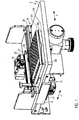
- the Fig. 1 and 2 let recognize the essential parts of the embodiment.
- This comprises a base plate 2, which forms a flat base 4 and the top side carries a traverse 6, which is movable in the direction of the directional arrow X and connected to the base plate 2.
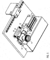
- the cross member has 6 lateral legs 8, which surround the base plate 2 (see. Fig. 2 ).
- There longitudinal guides 10 and a first drive 12 are provided, which meshes via a gear with a first rack 14 which is fixed to one of the legs 8. This is the result Possibility created to move the traverse 6 in a first direction, ie the X-direction relative to the base 4.
- the traverse 6 has a cover 16 which covers a second drive 18 which meshes via a gear with a second rack 20, which is connected to a holder 22 for a perforated field plate 24.
- the traverse 6 forms a transverse guide 26, via which the holder 22 in the second direction, ie the in Fig. 1 drawn Y-direction is movable.
- the two drives 12, 18 are coupled in terms of control with a logic unit which controls the two drives 12, 18 such that the perforated field plate 24 is held or arranged at a predetermined position.
- Fig. 2 shows a designated by reference numeral 28 lock for introducing a sample. Details of this lock 28 are the Fig. 5 refer to.
- the lock 28 has (see. Fig. 5 ) a movable sliding piston 30 which is penetrated by a receiving bore 32 and held displaceably in a Ausschiebezylinder 34.
- the discharge cylinder 34 has an introduction port 36 which is in alignment with a discharge opening 38 recessed in the base plate 2, and a discharge port 40 which is in alignment with a conduit section 42 connected to the discharge cylinder 34 and for sealingly bolting a catalytic combustion reactor, not shown adapted trained.
- the perforated field plate 24 shown has a first perforated field 44 with a plurality of equidistantly spaced rows of holes 46 and a second perforated field 48 formed by a single row of holes 46. Between the two hole fields 44, 48 a widened web 50 is provided.
- the Fig. 4 can also see in the line of sight behind the perforated plate 24, the ejection opening 38 and a marked with reference numeral 52 showcase, which allows the view of the receiving bore 32 in the second position of the sliding piston 30 through the wall of the Ausschiebezylinders 34, in which the receiving bore 32 with the line section 42 is aligned.
- the web 50 has a relation to the intermediate webs between rows of the first hole field 44 greater width.
- the width of the web 50 is chosen so that it slightly surmounted the diameter of the Abwerfö réelle 38 and thus is suitable to cover the Abwerfö réelle 38.
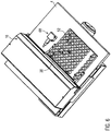
- the Fig. 1 and 3 show the first embodiment together with a transfer plate 54 which is placed in the said figures on the perforated field plate 24.
- the transfer plate 54 has the same dimensions as the perforated field plate 24.
- the transfer plate 54 has first and second transfer hole fields 56, 58, the holes of which are the same pitch as the holes of the first and second hole fields 44, 48 of the perforated field plate 24.
- the perforated field plate 24 holding and connected to the second toothed rail 20 holding arms 60 and a perpendicular thereto extending carrier 62, which are connected to the second drive 18, with a height corresponding to the height of the perforated plate 24 and the transfer plate 54 height provided above the pad 4.
- Fig. 1 further discloses a slide plate 64 provided above the perforated field plate 24 and slidably supported on the transfer plate 54 in a slide guide 66 recessed on the transfer plate 54.
- the sliding plate 64 closes off the holes of the transfer hole fields 56, 58 on the underside.
- the transfer plate 54 may initially be charged at a laboratory location and then placed with the slide plate 64 in position over the perforated field plate 24 and aligned therewith. Thereafter, the slide plate 64 is pulled, whereby the samples each fall from the holes of the transfer plate 54 into the corresponding holes 46 of the hole field plate 24.
- Fig. 3 64 sample positions are inscribed on the upper side of the sliding plate, so that each individual hole of the transfer plate 54 and thus of each individual hole of the perforated field plate 24 are assigned sample positions.
- the sample positions 1 to 64 correspond to the positions of the first hole field.
- These holes 46 have constant transverse and longitudinal spacings, ie constant distances in both the X and Y directions.
- the holes AH are holes of the second hole field 2, which are provided only in the X direction one behind the other, but there with the spacing of the holes 46 of the first hole field 44th
- the transfer plate 54 is lifted up to feed it again while performing the automated analysis by the embodiment.
- the drives 12 and 18 are operated in a controlled manner in order to bring the perforated field plate 24 with a selected hole 46 via the ejection opening 38. This will eject the sample from the corresponding hole 46, in the receiving bore 32 of the spool 30, which is in the first position.
- the sliding piston 30 is displaced in the Ausschiebezylinder 34, so that the receiving bore 32 is aligned with the line section 42. Due to gravity, the sample is thus dropped through the discharge opening 40 in the line section 42 and thus the reactor for the catalytic combustion.
- the sample is burned in a conventional manner with the addition of oxygen.
- the combustion gases are treated to separate, for example, water. Thereafter, the combustion gases are supplied to the adsorber, so that the ingredients of interest for the analysis can be separated and measured by the detector.
- the Fig. 6 shows an alternative embodiment with a camera 68, which is provided above the pad 4 and in the field of view, both the ejection opening 38 as well as the shop window 52 is located.
- the camera 68 is usually provided in the axial extension of the axis of the shop window 52 and thus can also detect the line section 42 optically.
- the camera 68 is connected to the central logic unit. It can detect both the ejection of the sample from the perforated field plate 24 through the ejection opening 38, as well as the ejection of the sample from the receiving bore 32 in the line section 42nd
- a gas line is connected, through which inert gas, such as helium, can be introduced into the interior of the Ausschiebezylinders 34.
- inert gas such as helium
- the further path of the sample from the conduit section 42 is in Fig. 7 shown schematically.
- the sample falls into a reactor UR for catalytic combustion.
- the resulting gases are fed to a reduction reactor RR.
- water contained in the combustion gas H 2 O is adsorbed.
- CO 2 contained in the gas is then removed from the gas.
- the nitrogen content is measured (at WLD) and the measured value is analyzed and output via a computer (PC).
- the in Fig. 7 The frame marked with reference numeral 70 illustrates those elements of the analysis device that are located within a housing, wherein on the top of the housing 70 of the Ausschiebezylinder 34 with the previously with reference to the FIGS. 1 to 6 is provided sample holder described, wherein the sample holder is only schematically indicated by a perforated disc (72).
Landscapes
- Chemical & Material Sciences (AREA)
- Health & Medical Sciences (AREA)
- General Health & Medical Sciences (AREA)
- Analytical Chemistry (AREA)
- Life Sciences & Earth Sciences (AREA)
- Immunology (AREA)
- Biochemistry (AREA)
- General Physics & Mathematics (AREA)
- Physics & Mathematics (AREA)
- Pathology (AREA)
- Chemical Kinetics & Catalysis (AREA)
- Engineering & Computer Science (AREA)
- Combustion & Propulsion (AREA)
- Hematology (AREA)
- Clinical Laboratory Science (AREA)
- Molecular Biology (AREA)
- Investigating Or Analyzing Non-Biological Materials By The Use Of Chemical Means (AREA)
Description
- Die folgende Erfindung betrifft einen Probenhalter einer Analyseeinrichtung für die Elementaranalyse, wie er beispielsweise aus der
DE 31 16 049 A1 bekannt ist. Die vorliegende Erfindung betrifft insbesondere eine Analyseeinrichtung zur quantitativen Elementaranalyse mit einem solchen Probenhalter. Sie will dabei insbesondere eine Analyseeinrichtung für die Elementaranalyse zur Bestimmung des Stickstoffgehaltes in einer Probe angeben. - Die
DE 31 16 049 A1 offenbart einen Probenhalter, der eine Schiene mit Ausnehmungen für einzusetzende Proben aufweist. Diese Schiene liegt auf einer Unterlage auf, die eine Auswurföffnung aufweist. Die Schiene ist an ihren Längsseiten von der Unterlage eingefasst, wodurch eine Führung gebildet wird. Ein Pneumatikmotor bewegt die Schiene entlang dieser Führung und jeweils eine Ausnehmung wird in Überdeckung mit der Auswurföffnung gebracht. Die Probe fällt dann durch die Auswurföffnung und wird einer Analyseeinrichtung zugeführt. - Eine Analyseeinrichtung für die Elementaranalyse ist beispielsweise aus der
EP 1 586 895 A1 bekannt. Diese Analyseeinrichtung hat einen Probenhalter, der durch ein rotierendes Rad mit einer Vielzahl auf dem Umfang mit gleichem Radius verteilt angeordneten Bohrungen gebildet ist, die hintereinander über eine Abwerföffnung gebracht werden, um die Probe der Analyse zugänglich zu machen. Die Probe fällt von dort in einen Reaktor für die katalytische Verbrennung. Hierzu wird für die Zeit der Verbrennung Sauerstoff eingeleitet. Die Menge an Sauerstoff wird gemäß der verwendeten Einwaage und der Art der Probe automatisch berechnet, sie erfolgt demgemäß stöchiometrisch. Stromabwärts des Reaktors ist ein Reduktionsreaktor vorgesehen, der der Reduktion der Probe dient. Stromabwärts des Reduktionsreaktors ist ein Adsorber vorgesehen, dem ein Detektor nachgeschaltet ist, um den Gehalt der zu analysierenden Elemente in den Gasstrom zu ermitteln. Der Detektor wirkt mit einer Logikeinheit zusammen, der die von dem Detektor erfassten Daten übermittelt werden, um anhand dieser Daten eine in der Regel quantitative Beurteilung der Probe hinsichtlich des Elementargehaltes zu erstellen. - Soweit vorstehend im Strömungsweg des Gases hintereinander angeordnete Bauelemente vorgestellt wurden, bedeutet dies nicht, dass nach der vorliegenden Erfindung nicht weitere Elemente innerhalb der Analyseeinrichtung dazwischen oder dahinter geschaltet sein können. So kann - wie aus dem Stand der Technik bekannt - hinter dem Reduktionsreaktor eine Wasserfalle und/oder ein oder mehrere selbstregenerierbare Wasserabsorber vorgesehen sein, der aus dem Gas Wasser ausführt. Des Weiteren kann für die Abtrennung des Kohlendioxids aus dem Gasstrom eine Vorrichtung zur Regeneration von Adsorberelementen vorgesehen sein, welche zyklisch aus dem Gasstrom entnommen und der Desorption zugeführt werden können. Diese Regeneration kann außerhalb eines die in Anspruch 5 genannten Elemente enthaltenen Gehäuses einer Analysevorrichtung vorgesehen sein. Ebenso gut können die Regenerationsmittel auch innerhalb des Gehäuses vorgesehen und zur automatisierten Desorption angepasst ausgebildet sein, wie dies beispielsweise mit
EP 1 586 895 A1 gelehrt wird. - Die vorliegende Erfindung will den an sich bekannten Probenhalter einer Analyseeinrichtung für die Elementaranalyse weiterbilden. Sie will dabei insbesondere die Probenzuführung für die Analyse verbessern und eine verbesserte Analyseeinrichtung angeben.
- Zur Lösung dieses Problems wird mit der vorliegenden Erfindung ein Probenhalter mit den Merkmalen von Anspruch 1 vorgeschlagen. Ein solcher Probenhalter umfasst eine Lochfeldplatte. Die Lochfeldplatte hat eine Vielzahl von, üblicherweise in einem vorbestimmten Raster zueinander vorgesehene Löcher. Die Löcher sind üblicherweise durch die Lochfeldplatte durchgehend ausgebildet, also als Durchgangsbohrungen. Sie sind üblicherweise zylindrisch. Das Raster führt zu einer Ausbildung eines zumindest ersten Lochfeldes, in dem die Löcher üblicherweise mit konstantem Quer- und Längsabstand relativ zueinander vorgesehen sind. Diese Lochfeldplatte ist auf einer Unterlage beweglich, die mit einer Abwerföffnung zum Abwerfen einer bestimmten Probe aus einem Loch der Lochfeldplatte versehen ist. Die Abwerföffnung hat hierzu üblicherweise einen Durchmesser, der hinsichtlich Form und Größe dem Durchmesser der Löcher des Lochfeldes entspricht. Die Lochfeldplatte ist translatorisch frei auf der Unterlage in einem kartesischen X-Y-Koordinatensystem beweglich, um einzelne Löcher der Lochfeldplatte über die Abwerföffnung zu verbringen und die Probe dort abzuwerfen.
- Die erfindungsgemäße Lösung erlaubt es, die Lochfeldplatte von der der Unterlage gegenüberliegenden Seite mit Proben zu befüllen. Gegenüber den vorbekannten Lösungen, bei denen die Lochfeldplatte entweder eindimensional verschoben oder mit einem rotierenden Rad gedreht wird, stellt die erfindungsgemäße Lösung eine flexiblere Möglichkeit bereit, Proben in die Analyseeinrichtung für die Elementaranalyse abzuwerfen. So können beispielsweise die Unterlage und die Beweglichkeit der Lochfeldplatte sowie die Abmessung der Lochfeldplatte so aufeinander abgestimmt sein, dass die Lochfeldplatte auch außerhalb der Abwerföffnung auf der Unterlage bewegt werden kann, d. h., die einzelnen Löcher der Lochfeldplatte an der Abwerföffnung vorbeigeführt werden können. Dadurch können unterschiedlich zueinander positionierte Lochfelder der Lochfeldplatte hintereinander der Abwerföffnung zugeführt und mit dieser zur Überdeckung gebracht werden. Durch die Anordnung der Löcher und das Einbringen der Proben in vorbestimmten Löcher der Lochfeldplatte ist damit nicht notwendigerweise auch die Reihenfolge für die Probenanalyse der einzelnen Proben in den Löchern vorgegeben. Des Weiteren besteht die Möglichkeit, die Löcher in einem vorbestimmten Raster vorzugsweise gebildet durch mehrere parallele Reihen von Löchern mit bevorzugt identischen Längs- und Querabständen in der Lochfeldplatte auszusparen, wodurch die Beschickung der Lochfeldplatte mit Proben deutlich vereinfacht wird.
- Gemäß einer bevorzugten Weiterbildung der vorliegenden Erfindung hat die Lochfeldplatte ein erstes Lochfeld und ein zweites Lochfeld, die über einen verbreiterten Steg voneinander getrennt sind. Das erste Lochfeld hat üblicherweise ein Raster mit mehreren nebeneinanderliegenden Reihen von Löchern. Dieses erste Lochfeld dient der üblichen Aufnahme der zu analysierenden Probe. Das zweite Lochfeld kann wenige oder lediglich ein einziges Loch umfassen. Sofern wenige Löcher vorgesehen sind, können diese Löcher des zweiten Lochfeldes mit dem gleichen Längs- oder Querabstand zueinander vorgesehen sein wie die Löcher des Rasters des ersten Lochfeldes. Allerdings kann auch nur eine einzige Reihe von Löchern das zweite Lochfeld ausbilden.
- Durch diese Ausgestaltung besteht die Möglichkeit, vorrangige Proben in das zweite Lochfeld einzubringen und die Steuerung zum Bewegen der Lochfeldplatte relativ zu der Unterlage so vorzunehmen, dass eine bevorzugte Probe außer der Reihe angefahren wird. Hierzu wird die Lochfeldplatte mit ihrem Steg zur Überdeckung mit der Abwerföffnung gebracht und entlang des Steges über die Abwerföffnung verfahren, bis diejenige Position des zweiten Lochfeldes erreicht ist, die die bevorzugt zu analysierende Probe enthält. Das an dieser Position befindliche Loch wird dann mit der Abwerföffnung zur Überdeckung gebracht.
- Es versteht sich von selbst, dass die Bewegung der Unterlage relativ zu der Abwerföffnung automatisiert über Antriebe erfolgen kann, bevorzugt computergesteuert über eine Logikeinheit. Diese Logikeinheit ist üblicherweise einheitlich mit der Logikeinheit zur Verarbeitung der von dem Detektor übermittelten Daten verknüpft, so dass die Identität der jeweils abgeworfenen Probe unmittelbar an die Logikeinheit zur Verarbeitung der von dem Detektor übermittelten Daten weitergegeben werden kann.
- Der verbreiterte Steg erstreckt sich üblicherweise parallel zu zwei sich parallel zueinander erstreckenden Reihen von Löchern, wobei die eine Reihe dem ersten Lochfeld und die andere Reihe dem zweiten Lochfeld zugeordnet ist. Üblicherweise geht der verbreiterte Steg von einer Randfläche zu der anderen Randfläche der Lochfeldplatte durch. Der Steg ist verbreitert, was bedeutet, dass dieser Steg breiter als derjenige Steg zwischen zwei benachbarten Reihen von Löchern beispielsweise des ersten Lochfeldes ist. Der Steg ist üblicherweise so breit ausgebildet, dass er die Abwerföffnung vollständig überdecken kann. So kann die Lochfeldplatte über die Abwerföffnung verfahren werden, ohne das diese auch nur teilweise freigegeben wir, um die priorisierte Probe des zweiten Lochfeldes anzufahren und aus dem zweiten Lochfeld abzuwerfen.
- Eine besonders einfache Ausgestaltung der Analyseeinrichtung wird gemäß einer bevorzugten Weiterbildung der vorliegenden Erfindung dadurch angegeben, dass die Lochfeldplatte an einer Traverse gehalten ist, die in einer ersten Richtung relativ zu der Unterlage beweglich ist. Die Unterlage wird gemäß dieser bevorzugten Ausgestaltung durch eine Grundplatte ausgeformt, die von der Traverse umgriffen ist. Unterhalb der Unterlage ist vorzugsweise ein Antrieb vorgesehen, der die Bewegung der Lochfeldplatte durch die Bewegung der Traverse in die erste Richtung vermittelt. Dieser Antrieb kann beispielsweise ein Motor sein, der mit einer Zahnstange kämmt, die an einem die Grundplatte umgreifenden Führungssteg der Traverse vorgesehen ist. Unter der Unterlage sind üblicherweise Führungselemente vorgesehen, die die Bewegung der Traverse in der ersten Richtung führen. Die Traverse hat ferner vorzugsweise einen eigenständigen Antrieb, der mit einer Halterung für die Lochfeldplatte zusammenwirkt und die Lochfeldplatte entlang der Traverse in einer zweiten Richtung bewegt. Diese zweite Richtung ist die Längsrichtung der Traverse und erstreckt sich üblicherweise quer zu der ersten Richtung. Durch die so ausgebildete Traverse kann die Lochfeldplatte dementsprechend im X-Y-Koordinatensystem auf der Ebene der Unterlage bewegt werden. Auch die Bewegung in der zweiten Richtung wird üblicherweise durch ein Zahnrad eines Antriebs und eine sich parallel zu der Ebene der Lochfeldplatte erstreckende und mit der Lochfeldplatte gekoppelte Zahnstange vermittelt.
- Zur leichteren Beschickung der Lochfeldplatte wird gemäß einer bevorzugten Weiterbildung der vorliegenden Erfindung eine Transferplatte vorgeschlagen, die mit einem zumindest dem ersten Lochfeld entsprechenden ersten Transferlochfeld versehen ist. Dieser Transferplatte ist eine Schiebeplatte zum unterseitigen Verschluss der Transferplatte zugeordnet. Die Schiebeplatte ist üblicherweise in einer Schiebeführung der Transferplatte gehalten und gegen Herausfallen in Richtung der an der Transferplatte ausgeformten Transferlöcher gesichert, indes in einer Richtung rechtwinklig hierzu verschieblich. Die Schiebeplatte schließt die in der Transferplatte ausgesparten Transferlöcher unterseitig ab. So kann die Transferplatte zunächst mit Proben bestückt werden. Die Transferplatte hat Formschlussmittel oder andere Positionierhilfen, um die beiderseitigen Lochfelder von Transferplatte einerseits und Lochfeldplatte andererseits zur Überdeckung zu bringen. Die Löcher der Lochfeldplatte sind dabei üblicherweise kodiert, wobei die Kodierung bevorzugt auf der Schiebeplatte vorgesehen ist, so dass die einzelnen Positionen innerhalb der Lochfeldplatte bei eingebrachter Schiebeplatte lesbar sind. Dies erleichtert das Zuordnen der Probe zu einer Position innerhalb der Lochfeldplatte. Die Transferplatte hat üblicherweise die gleichen Abmessungen wie die Lochfeldplatte, so dass eine fluchtende Anordnung der Löcher durch einfaches Überdecken der Ränder der beiderseitigen Lochplatten bewirkt werden kann. Danach wird die Schiebeplatte zwischen der Lochfeldplatte und der Transferplatte üblicherweise aus der Schiebeführung herausgezogen, so dass die Proben in die Löcher der Lochfeldplatte herunterfallen.
- Die Analyseeinrichtung ist üblicherweise so ausgerichtet, dass die Löcher der Lochfeldplatte sich in der vertikalen Richtung erstrecken, so dass sowohl das Überführen von der Transferplatte auf die Lochfeldplatte wie auch das Abwerfen der Probe in Richtung auf den Reaktor mittels Schwerkraft erfolgen kann. Entgegen dieser Bewegungsrichtung strömt üblicherweise Gas auch durch die Abwerföffnung aus, so dass sicher verhindert wird, dass Umgebungsluft mit der Probe in den Reaktor für die katalytische Verbrennung gelangt und dort das Probenergebnis verfälscht. Die Analyseeinrichtung hat üblicherweise ein Ventil, um zwischen einer Sauerstoffströmung in der Leitung und einer Inertgasströmung zu schalten, so dass verunreinigungsfrei bei Inertgas die Probe abgeworfen und danach auf Sauerstoffgas umgestellt werden kann, um eine rückstandsfreie katalytische Verbrennung zu bewirken.
- Die Transferplatte kann ein dem ersten und dem zweiten Lochfeld entsprechend ausgebildetes und jeweils mit diesem fluchtendes Lochfeld haben, so dass nach Aufsetzen der Transferplatte sowohl in üblicher Reihenfolge abzuarbeitende Proben wie auch Proben mit höherer Priorität beschickt werden können.
- Gemäß einer bevorzugten Weiterbildung der vorliegenden Erfindung ist auf der Unterseite der Unterlage ein Schiebekolben vorgesehen, der dichtend in einem Ausschiebezylinder geführt ist. Der Schiebekolben hat eine Aufnahmebohrung, die regelmäßig die gleiche axiale Ausrichtung wie die Abwerföffnung hat. Diese Aufnahmebohrung ist zwischen einer ersten Stellung und einer zweiten Stellung zyklisch hin- und her beweglich. In der ersten Stellung fluchtet die Aufnahmebohrung mit der Abwerföffnung. In der zweiten Stellung fluchtet die Aufnahmebohrung mit einem Leitungsabschnitt der Leitung für das Inertgas, insbesondere das Helium, und den Sauerstoff, der üblicherweise in streng vertikaler Erstreckung unmittelbar zu dem Reaktor für die katalytische Verbrennung führt.
- So kann die von der Unterlage in die Abwerföffnung abgeschobene Probe unmittelbar zu dem Reaktor gelangen. Der Schiebekolben ist üblicherweise in dem Ausschiebezylinder dichtend gehalten. Dazu sind üblicherweise unmittelbar benachbart zu der Aufnahmebohrung Nuten an dem Schiebekolben ausgespart, die Dichtringe halten, die mit der Innenumfangsfläche des Ausschiebezylinders zusammenwirken. Bereits der Ausschiebezylinder wird üblicherweise mit einer Quelle zumindest für das Inertgas verbunden, um einen unerwünschten Eintritt von atmosphärischer Luft in die Analyseeinrichtung durch die Abwerföffnung zu unterbinden. So bildet der besagte Ausschiebezylinder mit dem darin aufgenommen Schiebekolben eine Schleuse aus.
- Gemäß einer bevorzugten Weiterbildung der vorliegenden Erfindung hat die Unterlage ein Schaufenster. Dieses Schaufenster erlaubt den Blick durch die Unterlage auf die Aufnahmebohrung in der zweiten Stellung. Damit kann beobachtet werden, dass die Probe tatsächlich in den Leitungsabschnitt der Leitung abgeworfen wird (worden ist), wenn sich die Aufnahmebohrung in der zweiten Stellung befindet. Das Schaufenster dichtet dabei den Bereich oberhalb der Aufnahmebohrung ab, so dass ein Eintritt von Umgebungsluft durch das Schaufenster in die Aufnahmebohrung und zu dem Reaktor vermieden wird. Das Schaufenster ist üblicherweise bündig und absatzfrei mit der Oberfläche der Unterlage vorgesehen, so dass auch Proben über das Schaufenster verschoben werden können, ohne dass Teile der Proben im Bereich des Schaufensters hängenbleiben.
- Gemäß einer bevorzugten Weiterbildung der vorliegenden Erfindung ist eine Kamera vorgesehen, die auf die Abwerföffnung und/oder das Schaufenster gerichtet ist. Die Kamera ist üblicherweise mit einer zentralen Logikeinheit verbunden und überwacht optisch das Abwerfen der Probe durch die Abwerföffnung bzw. das Überführen der Probe in der zweiten Position der Aufnahmebohrung in den Leitungsabschnitt.
- Weitere Einzelheiten und Vorteile der vorliegenden Erfindung geben das nachfolgende Ausführungsbeispiel in Verbindung mit der Zeichnung. In dieser Zeichnung ist:
- Fig. 1
- eine perspektivische Seitenansicht auf die Oberseite des Ausführungsbeispiels;
- Fig.2
- eine perspektivische Ansicht auf die Unterseite des Ausführungsbeispiels;
- Fig. 3
- eine perspektivische Draufsicht auf die Oberseite des Ausführungsbeispiels;
- Fig. 4
- eine Draufsicht auf das Ausführungsbeispiel bei abgenommener Transferplatte;
- Fig. 5
- eine perspektivische Unteransicht des Ausführungsbeispiels, wobei Teile des Ausschiebezylinders transparent gezeichnet sind;
- Fig. 6
- eine perspektivische Draufsicht auf die Oberseite eines leicht abgewandelten zweiten Ausführungsbeispiels, und
- Fig. 7
- eine schematische Darstellung der wesentlichen Komponenten einer Elementaranalyse nach Dumas.
- Die
Fig. 1 und2 lassen die wesentlichen Teile des Ausführungsbeispiels erkennen. Dieses umfasst eine Grundplatte 2, die eine ebene Unterlage 4 ausbildet und oberseitig eine Traverse 6 führt, die in der Richtung des Richtungspfeils X beweglich und mit der Grundplatte 2 verbunden ist. Hierzu hat die Traverse 6 seitliche Schenkel 8, die die Grundplatte 2 umgreifen (vgl.Fig. 2 ). Dort sind Längsführungen 10 sowie ein erster Antrieb 12 vorgesehen, der über ein Zahnrad mit einer ersten Zahnstange 14 kämmt, die an einem der Schenkel 8 befestigt ist. Dadurch ist die Möglichkeit geschaffen, die Traverse 6 in einer ersten Richtung, d. h. der X-Richtung relativ zu der Unterlage 4 zu bewegen. - Die Traverse 6 hat eine Abdeckung 16, die einen zweiten Antrieb 18 abdeckt, der über ein Zahnrad mit einer zweiten Zahnstange 20 kämmt, die mit einer Halterung 22 für eine Lochfeldplatte 24 verbunden ist. Die Traverse 6 bildet eine Querführung 26 aus, über welche die Halterung 22 in der zweiten Richtung, d. h. der in
Fig. 1 eingezeichneten Y-Richtung beweglich ist. Die beiden Antriebe 12, 18 sind mit einer Logikeinheit steuerungsmäßig gekoppelt, die die beiden Antriebe 12, 18 so steuert, dass die Lochfeldplatte 24 an einer vorbestimmten Position gehalten bzw. angeordnet wird. -
Fig. 2 zeigt eine mit Bezugszeichen 28 gekennzeichnete Schleuse zum Einbringen einer Probe. Details dieser Schleuse 28 sind derFig. 5 zu entnehmen. Die Schleuse 28 hat (vgl.Fig. 5 ) einen beweglichen Schiebekolben 30, der von einer Aufnahmebohrung 32 durchsetzt und in einem Ausschiebezylinder 34 verschieblich gehalten ist. Der Ausschiebezylinder 34 hat eine Einbringöffnung 36, die mit einer in der Grundplatte 2 ausgesparten Abwerföffnung 38 fluchtet, und eine Ausbringöffnung 40, die mit einem Leitungsabschnitt 42 fluchtet, der mit dem Ausschiebezylinder 34 verbunden und zum abgedichteten Verschrauben eines nicht gezeigten Reaktors für die katalytische Verbrennung angepasst ausgebildet ist. - Die weiteren, die Analyseeinrichtung als solches bildenden Bestandteile sind vorwiegend nicht gezeigt. Insofern wird auf die
EP 1 586 895 A1 verwiesen, die die wesentlichen Komponenten für eine Analyseeinrichtung, insbesondere eine Analyseeinrichtung für die Analyse von Stickstoff in Proben, offenbart. Auf diese Offenbarung wird insofern verwiesen. - Die in
Fig. 4 gezeigte Lochfeldplatte 24 hat ein erstes Lochfeld 44 mit mehreren, in gleichmäßigen Abständen relativ zueinander vorgesehenen Reihen von Löchern 46 und ein zweites Lochfeld 48, welches durch eine einzige Reihe von Löchern 46 gebildet ist. Zwischen den beiden Lochfeldern 44, 48 ist ein verbreiterter Steg 50 vorgesehen. - Die
Fig. 4 lässt ferner in Blickrichtung hinter der Lochfeldplatte 24 die Abwerföffnung 38 sowie ein mit Bezugszeichen 52 gekennzeichnetes Schaufenster erkennen, welches durch die Wandung des Ausschiebezylinders 34 den Blick auf die Aufnahmebohrung 32 in der zweiten Stellung des Schiebekolbens 30 erlaubt, in welcher die Aufnahmebohrung 32 mit dem Leitungsabschnitt 42 fluchtet. - Wie
Fig. 4 vermittelt, hat der Steg 50 eine gegenüber den Zwischenstegen zwischen Reihen des ersten Lochfeldes 44 größere Breite. Die Breite des Steges 50 ist dabei so gewählt, dass sie den Durchmesser der Abwerföffnung 38 geringfügig überragt und damit geeignet ist, die Abwerföffnung 38 abzudecken. - Die
Fig. 1 und3 zeigen das erste Ausführungsbeispiel zusammen mit einer Transferplatte 54, die in den besagten Figuren auf die Lochfeldplatte 24 aufgelegt ist. Die Transferplatte 54 hat die gleichen Abmessungen wie die Lochfeldplatte 24. Auch hat die Transferplatte 54 erste und zweite Transferlochfelder 56, 58, deren Löcher mit gleichem Abstand bzw. Raster wie die Löcher des ersten und zweiten Lochfeldes 44, 48 der Lochfeldplatte 24 vorgesehen sind. Zur leichteren Positionierung sind die Lochfeldplatte 24 haltende und mit der zweiten Zahnschiene 20 verbundene Haltearme 60 sowie ein sich rechtwinklig hierzu erstreckender Träger 62, die mit dem zweiten Antrieb 18 verbunden sind, mit einer in etwa der Höhe der Lochfeldplatte 24 und der Transferplatte 54 entsprechenden Höhe über der Unterlage 4 vorgesehen. Dadurch wird eine Aufnahmeöffnung geschaffen, in welche die Transferplatte 54 zur genauen Überdeckung der beiderseitigen Löcher der Lochfeldplatte 24 und der Transferplatte 54 durch Anordnen der Platten 24, 54 übereinander eingebracht werden kann.Fig. 1 lässt ferner eine Schiebeplatte 64 erkennen, die oberhalb der Lochfeldplatte 24 vorgesehen ist und in einer Schiebeführung 66, die an der Transferplatte 54 ausgespart ist, verschieblich an der Transferplatte 54 gehalten ist. Die Schiebeplatte 64 verschließt die Löcher der Transferlochfelder 56, 58 unterseitig ab. So kann die Transferplatte 54 an einem Laborplatz zunächst beschickt und danach mit der Schiebeplatte 64 in Position über der Lochfeldplatte 24 angeordnet und daran ausgerichtet werden. Danach wird die Schiebeplatte 64 gezogen, wodurch die Proben jeweils von den Löchern der Transferplatte 54 in die entsprechenden Löcher 46 der Lochfeldplatte 24 fallen. - Wie insbesondere
Fig. 3 erkennen lässt, sind an der Oberseite der Schiebeplatte 64 Probenpositionen eingeschrieben, so dass jedem einzelnen Loch der Transferplatte 54 und damit jedem einzelnen Loch der Lochfeldplatte 24 Probenpositionen zugeordnet sind. Dabei entsprechen die Probenpositionen 1 bis 64 den Positionen des ersten Lochfeldes. Diese Löcher 46 haben konstante Quer- und Längsabstände, d. h. konstante Abstände sowohl in X- als auch in Y-Richtung. Die Löcher A-H sind Löcher des zweiten Lochfeldes 2, die lediglich in X-Richtung hintereinander vorgesehen sind, allerdings dort mit dem Abstand der Löcher 46 des ersten Lochfeldes 44. - Nach dem Beschicken der Lochfeldplatte 24 durch Ziehen der Schiebeplatte 64 wird die Transferplatte 54 abgehoben, um diese erneut zu beschicken, während die automatisierte Analyse durch das Ausführungsbeispiel durchgeführt wird. Dazu werden die Antriebe 12 und 18 gesteuert betrieben, um die Lochfeldplatte 24 mit einem ausgewählten Loch 46 über die Abwerföffnung 38 zu bringen. Dadurch wird die Probe aus dem entsprechenden Loch 46 abgeworfen, und zwar in die Aufnahmebohrung 32 des Schiebekolbens 30, der sich in der ersten Position befindet. Danach wird der Schiebekolben 30 in dem Ausschiebezylinder 34 verschoben, so dass die Aufnahmebohrung 32 mit dem Leitungsabschnitt 42 fluchtet. Aufgrund der Schwerkraft wird die Probe somit durch die Ausbringöffnung 40 in den Leitungsabschnitt 42 und damit den Reaktor für die katalytische Verbrennung abgeworfen. Die Probe wird in an sich bekannter Weise unter Zugabe von Sauerstoff verbrannt. Die Verbrennungsgase werden behandelt, um beispielsweise Wasser abzutrennen. Danach werden die Verbrennungsgase dem Adsorber zugeführt, so dass die für die Analyse interessierenden Inhaltstoffe abgetrennt und über den Detektor gemessen werden können.
- Die
Fig. 6 zeigt ein alternatives Ausführungsbeispiel mit einer Kamera 68, die oberhalb der Unterlage 4 vorgesehen ist und in deren Blickfeld sich sowohl die Abwerföffnung 38 wie auch das Schaufenster 52 befindet. Die Kamera 68 ist üblicherweise in axialer Verlängerung der Achse des Schaufensters 52 vorgesehen und kann somit auch den Leitungsabschnitt 42 optisch erfassen. Die Kamera 68 ist mit der zentralen Logikeinheit verbunden. Sie kann sowohl das Abwerfen der Probe aus der Lochfeldplatte 24 durch die Abwerföffnung 38 erkennen, wie auch das Abwerfen der Probe aus der Aufnahmebohrung 32 in den Leitungsabschnitt 42. - An den Ausschiebezylinder 34 ist eine Gasleitung angeschlossen, durch welche Inertgas, beispielsweise Helium, in das Innere des Ausschiebezylinders 34 eingebracht werden kann. Dadurch ist es möglich, in dem Ausschiebezylinder 34 zunächst originär enthaltene Umgebungsluft vor der Analyse durch die Abwerföffnung 38 auszutreiben, um innerhalb der Analyseeinrichtung eine Inertgasatmosphäre zu schaffen, die den zu messenden Stoff/das zu ermittelnde Element der Probe nicht enthält.
- Der weitere Weg der Probe von dem Leitungsabschnitt 42 ist in
Fig. 7 schematisch dargestellt. Die Probe fällt in einen Reaktor UR für eine katalytische Verbrennung. Die dabei entstehenden Gase werden einem Reduktionsreaktor RR zugeführt. Danach wird in dem Verbrennungsgas enthaltenes Wasser H2O adsorbiert. In dem Gas enthaltenes CO2 wird danach aus dem Gas entfernt. Schließlich wird der Stickstoffgehalt gemessen (bei WLD) und der gemessene Wert über einen Rechner (PC) analysiert und ausgegeben. Der inFig. 7 mit Bezugszeichen 70 gekennzeichnete Rahmen verdeutlicht dabei diejenigen Elemente der Analyseeinrichtung, die sich innerhalb eines Gehäuses befinden, wobei auf der Oberseite des Gehäuses 70 der Ausschiebezylinder 34 mit dem zuvor unter Bezugnahme auf dieFiguren 1 bis 6 beschriebenen Probenhalter vorgesehen ist, wobei der Probenhalter lediglich schematisch durch eine Lochscheibe (72) angedeutet ist. -
- 2
- Grundplatte
- 4
- Unterlage
- 6
- Traverse
- 8
- Schenkel
- 10
- Längsführung
- 12
- erster Antrieb
- 14
- erste Zahnstange
- 16
- Abdeckung
- 18
- zweiter Antrieb
- 20
- zweite Zahnstange
- 22
- Halterung
- 24
- Lochfeldplatte
- 26
- Querführung
- 28
- Schleuse
- 30
- Schiebekolben
- 32
- Aufnahmebohrung
- 34
- Ausschiebezylinder
- 36
- Einbringöffnung
- 38
- Abwerföffnung
- 40
- Ausbringöffnung
- 42
- Leitungsabschnitt
- 44
- erstes Lochfeld
- 46
- Loch
- 48
- zweites Lochfeld
- 50
- verbreiterter Steg
- 52
- Schaufenster
- 54
- Transferplatte
- 56
- erstes Transferlochfeld
- 58
- zweites Transferlochfeld
- 60
- Haltearme
- 62
- Träger
- 64
- Schiebeplatte
- 66
- Schiebeführung
- 68
- Kamera
- 70
- Rahmen
- 72
- Lochscheibe
Claims (8)
- Probenhalter einer Analyseeinrichtung für die Elementaranalyse, mit einer Lochfeldplatte (24), die mittels eines Antriebes (12, 18) auf einer Unterlage (4) beweglich ist, die mit einer Abwerföffnung (38) zum Abwerfen einer Probe versehen ist, dadurch gekennzeichnet, dass die Lochfeldplatte (24) translatorisch frei auf der Unterlage (4) in einem kartesischen X-Y-Koordinatensystem beweglich ist.
- Probenhalter nach Anspruch 1, dadurch gekennzeichnet, dass die Lochfeldplatte (24) ein erstes Lochfeld (44) und ein zweites Lochfeld (48) umfasst, die über einen Steg (50) voneinander getrennt sind, der breiter ist als ein Steg zwischen zwei benachbarten Reihen von Löchern des ersten Lochfelds (44).
- Probenhalter nach Anspruch 1 oder 2, dadurch gekennzeichnet, dass die Lochfeldplatte (24) an einer in einer ersten Richtung (X) relativ zu einer die Unterlage (4) ausbildenden Grundplatte (2) beweglichen und die Grundplatte (2) umgreifenden Traverse (6) gehalten ist und in Längsrichtung der Traverse (6) zu dieser verschieblich gehalten ist.
- Probenhalter nach Anspruch 2, gekennzeichnet durch eine Transferplatte (54), die mit einem zumindest dem ersten Lochfeld (44) entsprechenden ersten Transferlochfeld (56, 58) versehen ist, der eine Schiebeplatte (64) zum unterseitigen Verschluss der Transferplatte (54) zugeordnet ist, die nach dem Aufsetzen der Transferplatte (54) auf die Lochfeldplatte (24) zwischen der Lochfeldplatte und der Transferplatte herausziehbar ist.
- Analyseeinrichtung für die Elementaranalyse mit einem Probenhalter nach einem der vorherigen Ansprüche, einer Leitung (70) für Sauerstoff und Inertgas, einem Reaktor für die katalytische Verbrennung einer Probe, einem stromabwärts des Reaktors vorgesehenen Reduktionsreaktor, einem stromabwärts des Reduktionsreaktors vorgesehenen Adsorber, einem stromabwärts des Adsorbers vorgesehenen Detektor und einer Logikeinheit zur Verarbeitung der von dem Detektor übermittelten Daten.
- Analyseeinrichtung nach Anspruch 5, gekennzeichnet durch einen auf der Unterseite der Unterlage (4) vorgesehenen, dichtend in einem Ausschiebezylinder (34) geführten Schiebekolben (30) mit einer Aufnahmebohrung (32), die zwischen einer ersten Stellung, in der die Aufnahmebohrung (32) fluchtend zu der Abwerföffnung (38) angeordnet ist, und einer zweiten Stellung, der die Aufnahmebohrung (32) fluchtend zu einem zu dem Reaktor führenden Leitungsabschnitt (42) der Leitung angeordnet ist, zyklisch beweglich ist.
- Analyseeinrichtung nach Anspruch 6, gekennzeichnet durch ein in der Unterlage (4) ausgespartes Schaufenster (52) zur Überprüfung der Position der Aufnahmebohrung (32) in der zweiten Stellung.
- Analyseeinrichtung nach einem der Ansprüche 5 bis 7, gekennzeichnet durch eine auf die Abwerföffnung (38) und/oder das Schaufenster (52) gerichtete Kamera (68).
Applications Claiming Priority (1)
| Application Number | Priority Date | Filing Date | Title |
|---|---|---|---|
| DE202015004524.3U DE202015004524U1 (de) | 2015-06-24 | 2015-06-24 | Analyseeinrichtung für die Elementaranalyse |
Publications (2)
| Publication Number | Publication Date |
|---|---|
| EP3112859A1 EP3112859A1 (de) | 2017-01-04 |
| EP3112859B1 true EP3112859B1 (de) | 2018-01-24 |
Family
ID=56551124
Family Applications (1)
| Application Number | Title | Priority Date | Filing Date |
|---|---|---|---|
| EP16175981.6A Active EP3112859B1 (de) | 2015-06-24 | 2016-06-23 | Probenhalter einer analyseeinrichtung für die elementaranalyse und analyseeinrichtung für die elementaranalyse |
Country Status (5)
| Country | Link |
|---|---|
| US (1) | US10274442B2 (de) |
| EP (1) | EP3112859B1 (de) |
| JP (1) | JP6312747B2 (de) |
| DE (1) | DE202015004524U1 (de) |
| DK (1) | DK3112859T3 (de) |
Cited By (2)
| Publication number | Priority date | Publication date | Assignee | Title |
|---|---|---|---|---|
| EP4276458A1 (de) | 2022-05-12 | 2023-11-15 | C. Gerhardt GmbH & Co. KG | Analyseeinrichtung für die elementaranalyse |
| EP4276340A1 (de) | 2022-05-12 | 2023-11-15 | C. Gerhardt GmbH & Co. KG | Analyseeinrichtung für die elementaranalyse |
Families Citing this family (3)
| Publication number | Priority date | Publication date | Assignee | Title |
|---|---|---|---|---|
| WO2019147274A1 (en) | 2018-01-26 | 2019-08-01 | Hewlett-Packard Development Company, L.P. | Dispenser platforms |
| RU184021U1 (ru) * | 2018-07-31 | 2018-10-11 | Леонид Владимирович Илясов | Термохимический детектор газов |
| CN110164748A (zh) * | 2019-06-21 | 2019-08-23 | 中国科学技术大学 | 一种进样装置 |
Family Cites Families (15)
| Publication number | Priority date | Publication date | Assignee | Title |
|---|---|---|---|---|
| JPS597069B2 (ja) | 1976-02-16 | 1984-02-16 | 日立金属株式会社 | バタフライ弁 |
| DE2730214A1 (de) * | 1977-07-04 | 1979-01-11 | Franz Liebl | Mehrfachprobenstaender fuer labor- untersuchungen |
| IT1122396B (it) | 1979-08-02 | 1986-04-23 | Erba Strumentazione | Campionatore per sistemi analitici di rilevazione |
| DE3116049A1 (de) * | 1981-04-22 | 1982-11-11 | Antek Instruments GmbH, 4000 Düsseldorf | Verbrennungsapparat fuer die elementaranalyse |
| FR2560686B1 (fr) * | 1984-03-05 | 1986-11-07 | Rhone Poulenc Rech | Appareil de mineralisation pour le traitement individuel, de facon automatique, d'echantillons de produits places dans des recipients |
| US4731335A (en) * | 1985-09-13 | 1988-03-15 | Fisher Scientific Company | Method for treating thin samples on a surface employing capillary flow |
| JP2529725B2 (ja) | 1988-10-05 | 1996-09-04 | 倉敷紡績株式会社 | テ―ブル移動装置 |
| JP2949501B2 (ja) | 1989-03-29 | 1999-09-13 | 株式会社 堀場製作所 | 試料の分析用ガス抽出装置 |
| IT1256356B (it) | 1992-08-31 | 1995-12-01 | Dispositivo per l'alimentazione di campioni ad apparecchiature di analisi elementare | |
| IT1256355B (it) | 1992-08-31 | 1995-12-01 | Procedimento e apparecchiatura per la determinazione dell'azoto totale mediante analisi elementare | |
| US5314662A (en) * | 1993-03-08 | 1994-05-24 | Leco Corporation | Sample autoloader for use with an analytical combustion furnace |
| US5866072A (en) * | 1996-02-26 | 1999-02-02 | Cds Analytical, Inc. | Analytical pyrolysis autosampler |
| JP3062952U (ja) | 1999-04-09 | 1999-10-15 | 有限会社光信理化学製作所 | ガス発生抽出装置 |
| JP3878667B2 (ja) | 2002-09-17 | 2007-02-07 | シーケーディ株式会社 | 分注システム |
| ITMI20040740A1 (it) | 2004-04-15 | 2004-07-15 | Ecoenergetics S R L | Analizzatore automatico per la rilevazione di azoto proveniente da composti organici |
-
2015
- 2015-06-24 DE DE202015004524.3U patent/DE202015004524U1/de active Active
-
2016
- 2016-06-23 DK DK16175981.6T patent/DK3112859T3/en active
- 2016-06-23 EP EP16175981.6A patent/EP3112859B1/de active Active
- 2016-06-24 JP JP2016125289A patent/JP6312747B2/ja active Active
- 2016-06-24 US US15/191,926 patent/US10274442B2/en active Active
Non-Patent Citations (1)
| Title |
|---|
| None * |
Cited By (2)
| Publication number | Priority date | Publication date | Assignee | Title |
|---|---|---|---|---|
| EP4276458A1 (de) | 2022-05-12 | 2023-11-15 | C. Gerhardt GmbH & Co. KG | Analyseeinrichtung für die elementaranalyse |
| EP4276340A1 (de) | 2022-05-12 | 2023-11-15 | C. Gerhardt GmbH & Co. KG | Analyseeinrichtung für die elementaranalyse |
Also Published As
| Publication number | Publication date |
|---|---|
| US20160377563A1 (en) | 2016-12-29 |
| DK3112859T3 (en) | 2018-04-30 |
| DE202015004524U1 (de) | 2016-09-29 |
| JP6312747B2 (ja) | 2018-04-18 |
| US10274442B2 (en) | 2019-04-30 |
| JP2017009613A (ja) | 2017-01-12 |
| EP3112859A1 (de) | 2017-01-04 |
Similar Documents
| Publication | Publication Date | Title |
|---|---|---|
| EP3112859B1 (de) | Probenhalter einer analyseeinrichtung für die elementaranalyse und analyseeinrichtung für die elementaranalyse | |
| DE69308957T2 (de) | Verfahren und Vorrichtung zur Handhabung von Proben | |
| EP1628894B1 (de) | Foerderstrecke mit verstellbarem gelaender sowie stellantrieb | |
| DE3042915A1 (de) | Verfahren und vorrichtung zur automatischen analyse von fluidproben | |
| WO2006000115A1 (de) | Vorrichtung und verfahren zum anordnen von pipetten- oder dispenser-spitzen in einem system zum manipulieren von flüssigkeitsproben | |
| DE102006015535A1 (de) | Verfahren und Vorrichtung zur Analyse von Isotopenverhältnissen | |
| DE2245711A1 (de) | Verfahren und vorrichtung zum ruehren eines probenmaterials | |
| DE2224987A1 (de) | Verfahren und Gerät zum Einbringen einer Flüssigkeit oder eines Gases in ein | |
| DE3047265C2 (de) | Einrichtung zur Überführung von Probengefäßen in Auffanggefäße | |
| DE3835207C1 (de) | ||
| DE10043345C2 (de) | Vorrichtung zur vollautomatischen Festphasenextraktion | |
| DE60225968T2 (de) | Vorrichtung und Verfahren zur Bereitstellung von Bodenproben | |
| DE3028818C2 (de) | ||
| DE4009993C2 (de) | ||
| DE102011000891A1 (de) | Verfahren und Vorrichtung zum Bestimmen mindestens einer Veränderlichen | |
| DE2543012C3 (de) | ||
| DE602005002881T2 (de) | Vorrichtung und Verfahren zum Ordnen von Kugeln | |
| EP1814700B1 (de) | Vorrichtung zum ankoppeln einer zusatzeinrichtung | |
| DE2357062C2 (de) | Verfahren und Vorrichtung zum Entnehmen einer Probe aus einer Förderleitung | |
| DE2406357C3 (de) | Vorrichtung zum Einfuhren von Konturenstäben in Doppelgewebe zur Herstellung von Röhrchentaschen für Akkumulatorelektroden | |
| EP3673263B1 (de) | Verfahren zur bereitstellung einer substanzmenge | |
| DE19826244C2 (de) | Gerät zur Aufnahme und Übertragung biologischer Proben | |
| DE2950407C2 (de) | Vorrichtung zum Verschieben einer in einem Probenhalter angeordneten radioaktiven Probe in eine strahlungsgeschirmte Meßkammer eines automatischen Gammastrahlungszählgerätes | |
| DE10310311A1 (de) | Probenehmer und Anordnung zur Probenahme für Analysen zur Bestimmung von Kontaminationen | |
| DE927659C (de) | Vorrichtung zum Nachweis von Gasen oder Schwebstoffen in Luft |
Legal Events
| Date | Code | Title | Description |
|---|---|---|---|
| PUAI | Public reference made under article 153(3) epc to a published international application that has entered the european phase |
Free format text: ORIGINAL CODE: 0009012 |
|
| AK | Designated contracting states |
Kind code of ref document: A1 Designated state(s): AL AT BE BG CH CY CZ DE DK EE ES FI FR GB GR HR HU IE IS IT LI LT LU LV MC MK MT NL NO PL PT RO RS SE SI SK SM TR |
|
| AX | Request for extension of the european patent |
Extension state: BA ME |
|
| 17P | Request for examination filed |
Effective date: 20170222 |
|
| RBV | Designated contracting states (corrected) |
Designated state(s): AL AT BE BG CH CY CZ DE DK EE ES FI FR GB GR HR HU IE IS IT LI LT LU LV MC MK MT NL NO PL PT RO RS SE SI SK SM TR |
|
| GRAP | Despatch of communication of intention to grant a patent |
Free format text: ORIGINAL CODE: EPIDOSNIGR1 |
|
| RIC1 | Information provided on ipc code assigned before grant |
Ipc: G01N 35/02 20060101ALI20170630BHEP Ipc: G01N 31/12 20060101AFI20170630BHEP Ipc: G01N 35/04 20060101ALN20170630BHEP Ipc: G01N 31/00 20060101ALN20170630BHEP |
|
| RIC1 | Information provided on ipc code assigned before grant |
Ipc: G01N 31/12 20060101AFI20170712BHEP Ipc: G01N 35/02 20060101ALI20170712BHEP Ipc: G01N 31/00 20060101ALN20170712BHEP Ipc: G01N 35/04 20060101ALI20170712BHEP |
|
| INTG | Intention to grant announced |
Effective date: 20170810 |
|
| GRAS | Grant fee paid |
Free format text: ORIGINAL CODE: EPIDOSNIGR3 |
|
| GRAA | (expected) grant |
Free format text: ORIGINAL CODE: 0009210 |
|
| AK | Designated contracting states |
Kind code of ref document: B1 Designated state(s): AL AT BE BG CH CY CZ DE DK EE ES FI FR GB GR HR HU IE IS IT LI LT LU LV MC MK MT NL NO PL PT RO RS SE SI SK SM TR |
|
| REG | Reference to a national code |
Ref country code: GB Ref legal event code: FG4D Free format text: NOT ENGLISH |
|
| REG | Reference to a national code |
Ref country code: CH Ref legal event code: EP |
|
| REG | Reference to a national code |
Ref country code: AT Ref legal event code: REF Ref document number: 966065 Country of ref document: AT Kind code of ref document: T Effective date: 20180215 |
|
| REG | Reference to a national code |
Ref country code: IE Ref legal event code: FG4D Free format text: LANGUAGE OF EP DOCUMENT: GERMAN |
|
| REG | Reference to a national code |
Ref country code: DE Ref legal event code: R096 Ref document number: 502016000490 Country of ref document: DE |
|
| REG | Reference to a national code |
Ref country code: DK Ref legal event code: T3 Effective date: 20180423 |
|
| REG | Reference to a national code |
Ref country code: NL Ref legal event code: MP Effective date: 20180124 |
|
| REG | Reference to a national code |
Ref country code: LT Ref legal event code: MG4D |
|
| REG | Reference to a national code |
Ref country code: EE Ref legal event code: FG4A Ref document number: E015392 Country of ref document: EE Effective date: 20180423 |
|
| REG | Reference to a national code |
Ref country code: FR Ref legal event code: PLFP Year of fee payment: 3 |
|
| PG25 | Lapsed in a contracting state [announced via postgrant information from national office to epo] |
Ref country code: NL Free format text: LAPSE BECAUSE OF FAILURE TO SUBMIT A TRANSLATION OF THE DESCRIPTION OR TO PAY THE FEE WITHIN THE PRESCRIBED TIME-LIMIT Effective date: 20180124 |
|
| PG25 | Lapsed in a contracting state [announced via postgrant information from national office to epo] |
Ref country code: ES Free format text: LAPSE BECAUSE OF FAILURE TO SUBMIT A TRANSLATION OF THE DESCRIPTION OR TO PAY THE FEE WITHIN THE PRESCRIBED TIME-LIMIT Effective date: 20180124 Ref country code: CY Free format text: LAPSE BECAUSE OF FAILURE TO SUBMIT A TRANSLATION OF THE DESCRIPTION OR TO PAY THE FEE WITHIN THE PRESCRIBED TIME-LIMIT Effective date: 20180124 Ref country code: FI Free format text: LAPSE BECAUSE OF FAILURE TO SUBMIT A TRANSLATION OF THE DESCRIPTION OR TO PAY THE FEE WITHIN THE PRESCRIBED TIME-LIMIT Effective date: 20180124 Ref country code: NO Free format text: LAPSE BECAUSE OF FAILURE TO SUBMIT A TRANSLATION OF THE DESCRIPTION OR TO PAY THE FEE WITHIN THE PRESCRIBED TIME-LIMIT Effective date: 20180424 Ref country code: LT Free format text: LAPSE BECAUSE OF FAILURE TO SUBMIT A TRANSLATION OF THE DESCRIPTION OR TO PAY THE FEE WITHIN THE PRESCRIBED TIME-LIMIT Effective date: 20180124 Ref country code: HR Free format text: LAPSE BECAUSE OF FAILURE TO SUBMIT A TRANSLATION OF THE DESCRIPTION OR TO PAY THE FEE WITHIN THE PRESCRIBED TIME-LIMIT Effective date: 20180124 |
|
| PG25 | Lapsed in a contracting state [announced via postgrant information from national office to epo] |
Ref country code: LV Free format text: LAPSE BECAUSE OF FAILURE TO SUBMIT A TRANSLATION OF THE DESCRIPTION OR TO PAY THE FEE WITHIN THE PRESCRIBED TIME-LIMIT Effective date: 20180124 Ref country code: SE Free format text: LAPSE BECAUSE OF FAILURE TO SUBMIT A TRANSLATION OF THE DESCRIPTION OR TO PAY THE FEE WITHIN THE PRESCRIBED TIME-LIMIT Effective date: 20180124 Ref country code: RS Free format text: LAPSE BECAUSE OF FAILURE TO SUBMIT A TRANSLATION OF THE DESCRIPTION OR TO PAY THE FEE WITHIN THE PRESCRIBED TIME-LIMIT Effective date: 20180124 Ref country code: BG Free format text: LAPSE BECAUSE OF FAILURE TO SUBMIT A TRANSLATION OF THE DESCRIPTION OR TO PAY THE FEE WITHIN THE PRESCRIBED TIME-LIMIT Effective date: 20180424 Ref country code: GR Free format text: LAPSE BECAUSE OF FAILURE TO SUBMIT A TRANSLATION OF THE DESCRIPTION OR TO PAY THE FEE WITHIN THE PRESCRIBED TIME-LIMIT Effective date: 20180425 Ref country code: IS Free format text: LAPSE BECAUSE OF FAILURE TO SUBMIT A TRANSLATION OF THE DESCRIPTION OR TO PAY THE FEE WITHIN THE PRESCRIBED TIME-LIMIT Effective date: 20180524 Ref country code: PL Free format text: LAPSE BECAUSE OF FAILURE TO SUBMIT A TRANSLATION OF THE DESCRIPTION OR TO PAY THE FEE WITHIN THE PRESCRIBED TIME-LIMIT Effective date: 20180124 |
|
| PG25 | Lapsed in a contracting state [announced via postgrant information from national office to epo] |
Ref country code: MT Free format text: LAPSE BECAUSE OF FAILURE TO SUBMIT A TRANSLATION OF THE DESCRIPTION OR TO PAY THE FEE WITHIN THE PRESCRIBED TIME-LIMIT Effective date: 20180124 |
|
| REG | Reference to a national code |
Ref country code: DE Ref legal event code: R097 Ref document number: 502016000490 Country of ref document: DE |
|
| PG25 | Lapsed in a contracting state [announced via postgrant information from national office to epo] |
Ref country code: AL Free format text: LAPSE BECAUSE OF FAILURE TO SUBMIT A TRANSLATION OF THE DESCRIPTION OR TO PAY THE FEE WITHIN THE PRESCRIBED TIME-LIMIT Effective date: 20180124 |
|
| PG25 | Lapsed in a contracting state [announced via postgrant information from national office to epo] |
Ref country code: SM Free format text: LAPSE BECAUSE OF FAILURE TO SUBMIT A TRANSLATION OF THE DESCRIPTION OR TO PAY THE FEE WITHIN THE PRESCRIBED TIME-LIMIT Effective date: 20180124 Ref country code: SK Free format text: LAPSE BECAUSE OF FAILURE TO SUBMIT A TRANSLATION OF THE DESCRIPTION OR TO PAY THE FEE WITHIN THE PRESCRIBED TIME-LIMIT Effective date: 20180124 Ref country code: CZ Free format text: LAPSE BECAUSE OF FAILURE TO SUBMIT A TRANSLATION OF THE DESCRIPTION OR TO PAY THE FEE WITHIN THE PRESCRIBED TIME-LIMIT Effective date: 20180124 |
|
| PLBE | No opposition filed within time limit |
Free format text: ORIGINAL CODE: 0009261 |
|
| STAA | Information on the status of an ep patent application or granted ep patent |
Free format text: STATUS: NO OPPOSITION FILED WITHIN TIME LIMIT |
|
| 26N | No opposition filed |
Effective date: 20181025 |
|
| PG25 | Lapsed in a contracting state [announced via postgrant information from national office to epo] |
Ref country code: SI Free format text: LAPSE BECAUSE OF FAILURE TO SUBMIT A TRANSLATION OF THE DESCRIPTION OR TO PAY THE FEE WITHIN THE PRESCRIBED TIME-LIMIT Effective date: 20180124 |
|
| REG | Reference to a national code |
Ref country code: BE Ref legal event code: MM Effective date: 20180630 |
|
| REG | Reference to a national code |
Ref country code: IE Ref legal event code: MM4A |
|
| PG25 | Lapsed in a contracting state [announced via postgrant information from national office to epo] |
Ref country code: MC Free format text: LAPSE BECAUSE OF FAILURE TO SUBMIT A TRANSLATION OF THE DESCRIPTION OR TO PAY THE FEE WITHIN THE PRESCRIBED TIME-LIMIT Effective date: 20180124 Ref country code: LU Free format text: LAPSE BECAUSE OF NON-PAYMENT OF DUE FEES Effective date: 20180623 |
|
| PG25 | Lapsed in a contracting state [announced via postgrant information from national office to epo] |
Ref country code: IE Free format text: LAPSE BECAUSE OF NON-PAYMENT OF DUE FEES Effective date: 20180623 |
|
| PG25 | Lapsed in a contracting state [announced via postgrant information from national office to epo] |
Ref country code: BE Free format text: LAPSE BECAUSE OF NON-PAYMENT OF DUE FEES Effective date: 20180630 |
|
| REG | Reference to a national code |
Ref country code: CH Ref legal event code: PL |
|
| PG25 | Lapsed in a contracting state [announced via postgrant information from national office to epo] |
Ref country code: TR Free format text: LAPSE BECAUSE OF FAILURE TO SUBMIT A TRANSLATION OF THE DESCRIPTION OR TO PAY THE FEE WITHIN THE PRESCRIBED TIME-LIMIT Effective date: 20180124 |
|
| PG25 | Lapsed in a contracting state [announced via postgrant information from national office to epo] |
Ref country code: LI Free format text: LAPSE BECAUSE OF NON-PAYMENT OF DUE FEES Effective date: 20190630 Ref country code: CH Free format text: LAPSE BECAUSE OF NON-PAYMENT OF DUE FEES Effective date: 20190630 Ref country code: PT Free format text: LAPSE BECAUSE OF FAILURE TO SUBMIT A TRANSLATION OF THE DESCRIPTION OR TO PAY THE FEE WITHIN THE PRESCRIBED TIME-LIMIT Effective date: 20180124 |
|
| PG25 | Lapsed in a contracting state [announced via postgrant information from national office to epo] |
Ref country code: HU Free format text: LAPSE BECAUSE OF FAILURE TO SUBMIT A TRANSLATION OF THE DESCRIPTION OR TO PAY THE FEE WITHIN THE PRESCRIBED TIME-LIMIT; INVALID AB INITIO Effective date: 20160623 Ref country code: MK Free format text: LAPSE BECAUSE OF NON-PAYMENT OF DUE FEES Effective date: 20180124 Ref country code: RO Free format text: LAPSE BECAUSE OF FAILURE TO SUBMIT A TRANSLATION OF THE DESCRIPTION OR TO PAY THE FEE WITHIN THE PRESCRIBED TIME-LIMIT Effective date: 20180124 |
|
| REG | Reference to a national code |
Ref country code: EE Ref legal event code: MM4A Ref document number: E015392 Country of ref document: EE Effective date: 20200630 |
|
| PG25 | Lapsed in a contracting state [announced via postgrant information from national office to epo] |
Ref country code: EE Free format text: LAPSE BECAUSE OF NON-PAYMENT OF DUE FEES Effective date: 20200630 |
|
| REG | Reference to a national code |
Ref country code: EE Ref legal event code: TH4A Ref document number: E015392 Country of ref document: EE |
|
| REG | Reference to a national code |
Ref country code: AT Ref legal event code: MM01 Ref document number: 966065 Country of ref document: AT Kind code of ref document: T Effective date: 20210623 |
|
| PG25 | Lapsed in a contracting state [announced via postgrant information from national office to epo] |
Ref country code: AT Free format text: LAPSE BECAUSE OF NON-PAYMENT OF DUE FEES Effective date: 20210623 |
|
| PGFP | Annual fee paid to national office [announced via postgrant information from national office to epo] |
Ref country code: IT Payment date: 20230629 Year of fee payment: 8 |
|
| PGFP | Annual fee paid to national office [announced via postgrant information from national office to epo] |
Ref country code: GB Payment date: 20240625 Year of fee payment: 9 |
|
| PGFP | Annual fee paid to national office [announced via postgrant information from national office to epo] |
Ref country code: DE Payment date: 20240626 Year of fee payment: 9 |
|
| PGFP | Annual fee paid to national office [announced via postgrant information from national office to epo] |
Ref country code: DK Payment date: 20240625 Year of fee payment: 9 |
|
| PGFP | Annual fee paid to national office [announced via postgrant information from national office to epo] |
Ref country code: FR Payment date: 20240626 Year of fee payment: 9 Ref country code: EE Payment date: 20240625 Year of fee payment: 9 |