EP1116847A2 - Window or door - Google Patents
Window or door Download PDFInfo
- Publication number
- EP1116847A2 EP1116847A2 EP00125850A EP00125850A EP1116847A2 EP 1116847 A2 EP1116847 A2 EP 1116847A2 EP 00125850 A EP00125850 A EP 00125850A EP 00125850 A EP00125850 A EP 00125850A EP 1116847 A2 EP1116847 A2 EP 1116847A2
- Authority
- EP
- European Patent Office
- Prior art keywords
- wing
- casserole
- frame
- window
- door according
- Prior art date
- Legal status (The legal status is an assumption and is not a legal conclusion. Google has not performed a legal analysis and makes no representation as to the accuracy of the status listed.)
- Granted
Links
- 239000002991 molded plastic Substances 0.000 claims description 2
- 229910001229 Pot metal Inorganic materials 0.000 claims 1
- 239000000463 material Substances 0.000 description 3
- 235000001674 Agaricus brunnescens Nutrition 0.000 description 2
- 239000003795 chemical substances by application Substances 0.000 description 2
- 238000006073 displacement reaction Methods 0.000 description 2
- 230000000694 effects Effects 0.000 description 2
- 230000035515 penetration Effects 0.000 description 2
- 239000004033 plastic Substances 0.000 description 2
- 125000006850 spacer group Chemical group 0.000 description 2
- 229910000831 Steel Inorganic materials 0.000 description 1
- 230000001154 acute effect Effects 0.000 description 1
- 238000005452 bending Methods 0.000 description 1
- 238000005553 drilling Methods 0.000 description 1
- 238000004519 manufacturing process Methods 0.000 description 1
- 238000007665 sagging Methods 0.000 description 1
- 239000010959 steel Substances 0.000 description 1
- 239000002023 wood Substances 0.000 description 1
Images


Classifications
-
- E—FIXED CONSTRUCTIONS
- E05—LOCKS; KEYS; WINDOW OR DOOR FITTINGS; SAFES
- E05F—DEVICES FOR MOVING WINGS INTO OPEN OR CLOSED POSITION; CHECKS FOR WINGS; WING FITTINGS NOT OTHERWISE PROVIDED FOR, CONCERNED WITH THE FUNCTIONING OF THE WING
- E05F7/00—Accessories for wings not provided for in other groups of this subclass
- E05F7/005—Aligning devices for wings
-
- E—FIXED CONSTRUCTIONS
- E05—LOCKS; KEYS; WINDOW OR DOOR FITTINGS; SAFES
- E05C—BOLTS OR FASTENING DEVICES FOR WINGS, SPECIALLY FOR DOORS OR WINDOWS
- E05C9/00—Arrangements of simultaneously actuated bolts or other securing devices at well-separated positions on the same wing
- E05C9/06—Arrangements of simultaneously actuated bolts or other securing devices at well-separated positions on the same wing with three or more sliding bars
- E05C9/063—Arrangements of simultaneously actuated bolts or other securing devices at well-separated positions on the same wing with three or more sliding bars extending along three or more sides of the wing or frame
- E05C9/066—Locks for windows or doors specially adapted for tilt and turn
-
- E—FIXED CONSTRUCTIONS
- E05—LOCKS; KEYS; WINDOW OR DOOR FITTINGS; SAFES
- E05C—BOLTS OR FASTENING DEVICES FOR WINGS, SPECIALLY FOR DOORS OR WINDOWS
- E05C9/00—Arrangements of simultaneously actuated bolts or other securing devices at well-separated positions on the same wing
- E05C9/18—Details of fastening means or of fixed retaining means for the ends of bars
- E05C9/1825—Fastening means
- E05C9/1833—Fastening means performing sliding movements
- E05C9/185—Fastening means performing sliding movements parallel with actuating bar
-
- E—FIXED CONSTRUCTIONS
- E05—LOCKS; KEYS; WINDOW OR DOOR FITTINGS; SAFES
- E05C—BOLTS OR FASTENING DEVICES FOR WINGS, SPECIALLY FOR DOORS OR WINDOWS
- E05C9/00—Arrangements of simultaneously actuated bolts or other securing devices at well-separated positions on the same wing
- E05C9/24—Means for transmitting movements between vertical and horizontal sliding bars, rods or cables for the fastening of wings, e.g. corner guides
-
- E—FIXED CONSTRUCTIONS
- E05—LOCKS; KEYS; WINDOW OR DOOR FITTINGS; SAFES
- E05B—LOCKS; ACCESSORIES THEREFOR; HANDCUFFS
- E05B17/00—Accessories in connection with locks
- E05B17/20—Means independent of the locking mechanism for preventing unauthorised opening, e.g. for securing the bolt in the fastening position
- E05B17/2084—Means to prevent forced opening by attack, tampering or jimmying
-
- E—FIXED CONSTRUCTIONS
- E05—LOCKS; KEYS; WINDOW OR DOOR FITTINGS; SAFES
- E05F—DEVICES FOR MOVING WINGS INTO OPEN OR CLOSED POSITION; CHECKS FOR WINGS; WING FITTINGS NOT OTHERWISE PROVIDED FOR, CONCERNED WITH THE FUNCTIONING OF THE WING
- E05F7/00—Accessories for wings not provided for in other groups of this subclass
- E05F7/06—Devices for taking the weight of the wing, arranged away from the hinge axis
-
- E—FIXED CONSTRUCTIONS
- E05—LOCKS; KEYS; WINDOW OR DOOR FITTINGS; SAFES
- E05Y—INDEXING SCHEME ASSOCIATED WITH SUBCLASSES E05D AND E05F, RELATING TO CONSTRUCTION ELEMENTS, ELECTRIC CONTROL, POWER SUPPLY, POWER SIGNAL OR TRANSMISSION, USER INTERFACES, MOUNTING OR COUPLING, DETAILS, ACCESSORIES, AUXILIARY OPERATIONS NOT OTHERWISE PROVIDED FOR, APPLICATION THEREOF
- E05Y2900/00—Application of doors, windows, wings or fittings thereof
- E05Y2900/10—Application of doors, windows, wings or fittings thereof for buildings or parts thereof
- E05Y2900/13—Type of wing
- E05Y2900/132—Doors
-
- E—FIXED CONSTRUCTIONS
- E05—LOCKS; KEYS; WINDOW OR DOOR FITTINGS; SAFES
- E05Y—INDEXING SCHEME ASSOCIATED WITH SUBCLASSES E05D AND E05F, RELATING TO CONSTRUCTION ELEMENTS, ELECTRIC CONTROL, POWER SUPPLY, POWER SIGNAL OR TRANSMISSION, USER INTERFACES, MOUNTING OR COUPLING, DETAILS, ACCESSORIES, AUXILIARY OPERATIONS NOT OTHERWISE PROVIDED FOR, APPLICATION THEREOF
- E05Y2900/00—Application of doors, windows, wings or fittings thereof
- E05Y2900/10—Application of doors, windows, wings or fittings thereof for buildings or parts thereof
- E05Y2900/13—Type of wing
- E05Y2900/148—Windows
Definitions
- the object of the invention relates to a window or a door the preamble of claim 1.
- the object of the invention is therefore to a window or a door ready in which the disadvantages of the prior art be avoided.
- This task can be solved by using a window or a door according to the preamble of claim 1 the features of the characterizing part of claim 1 can be realized.
- An embodiment in which the casserole is particularly advantageous is angular and encompasses the lower wing edge remote from the axis of rotation and with one leg at least approximately up to one Reached bolt engagement reaches. Then it works Casserole in both directions along both the lower horizontal Wing or frame legs as well, at least in one direction perpendicular to it and in the direction of the lower wing edge.
- the casserole serves within certain limits Relative orientation of the wing relative to the frame, so that after the inclusion of the wing in the frame of the wing and thus also the locking members a defined position with respect to the frame and so that the bolt engagements.
- Another advantageous embodiment provides that the bolt engagement as Tilt lock is formed. This allows the one anyway Windows or a door to be provided with a tilt and turn fitting Tilt lock on the lower horizontal frame spar as Interlocking device interact with the angular casserole.
- the casserole can be produced particularly inexpensively if this is designed as a molded plastic part.
- the casserole can be doing so after further training without impairing one Install the espagnolette fitting if the casserole is Fastening screws are attached to the wing, the side next to one Engage the hardware groove in the sash. This may cause the casserole can also be arranged later and there are fastenings regardless of drilling or similar facilities on the Espagnolette fitting possible.
- a particularly advantageous embodiment results in particular with the features of claim 2 when the casserole engages over a corner deflection fitting.
- This can on the one hand additional attachment of the corner deflection fitting to the exposed to considerable loads, particularly in the event of a break-in is, on the other hand, this also makes it particularly useful Position of the casserole reached, because this means that it is directly on two Can attack wing edges.
- a configuration is also expedient in which the Bolt engagement on its longitudinal ends facing the casserole with the Enlarging contact edge of the bolt engagement, parallel to Longitudinal end of the casserole is provided inclined surfaces.
- the fitting as Burglar-resistant fitting is designed so that the locking members and bolt interventions have special strengths and also can be loaded perpendicular to the wing plane.
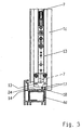
- Fig. 1 shows a tilt and turn window with a wing 1, which consists of four Wing spars 1a, 1b, 1c and 1d is formed.
- the wing 1 is over a Tilt-and-turn joint 2 and a scissor joint 3 that does not have one Display device cooperates, rotatable and tiltable on Frame 4 attached, which in turn from four frame bars 4a, 4b, 4c and 4d is composed.
- an operating handle 5 corresponding functional and locking elements, not shown here of a connecting rod fitting, which is also not visible here, of which a corner deflection fitting 6 is shown in FIG. 2.
- Fig. 2 shows the lower wing edge or corner of the Wing 1 and this assigned in a hardware groove 7 Corner deflection fitting 6.
- the corner deflection fitting 6 has via a drive rod 8 displaceable locking member 9, on which lower horizontal frame leg 5d a fixed latch engagement 10 is assigned.
- the locking member 9 is designed as a mushroom head pin and is by the control handle 5 in a known manner between the Switch positions for turning, tilting and locking shifted.
- the locking member 9 by a lateral opening 11 of the bolt engagement 10 pass through, so that the Wing 1 can be opened for rotation.
- Lock member 9 move into a locking pocket of locking engagement 10, see above the wing 1 on the lower horizontal frame beam 4d is set.
- the bolt engagement 10 shown in Fig. 2 is therefore as Tilt lock designed. All on the wing spars 1a, 1b and 1c Existing locking links are assigned to them Bolt engagements on the frame bars 4a, 4b and 4c are pulled out.
- the corner deflection fitting 6 also has a faceplate or a cover bracket 12 with which the hardware groove 7 is covered.
- the cover angle 12 lies on one level with the wing rebate 13, a frame fold 14, separated by the air gap area 15, lies opposite, the distance between wing fold 13 and Frame rebate is referred to as rebate clearance and is marked with 15a is.
- the locking members 9 and locking interventions 10 are in this Air gap area and are by a wing flap 16 at closed wing 1 covered, as Fig. 3 shows.
- the frame fold 14 can have projecting webs 17 or grooves 18, such as also recognizable from FIG. 3.
- a casserole 20 is also protruding into the rebate air area 15 provided that on the cover bracket 12 and wing rebate 13 of the upright frame spar 1c and the lower horizontal wing spar 1d applies equally.
- the angular casserole therefore embraces the Corner deflection fitting 6 in the immediate corner area 21 the legs 22, 23 each project so far into the rebate air area 15, that the casserole 20, the projecting webs 17 is ideal on all sides aligned wing 1 with little play when closing the Wing 1 can happen.
- the casserole 20 is for Avoidance of this provided with an inclined leading edge 24 which a relative orientation when the wing 1 enters the frame 4 of the wing 1 to the frame 4 until the wing 1 at completely closed wing 1 by means of the casserole 20 on the Frame fold surface 14 or its projecting webs 17 supports.
- the casserole 20 has yet another function. At a A break-in attempt is aimed at a possible attack against wing 1 and its locking in the frame 4.
- the locking members are 9 due to their mushroom-shaped shape, it is difficult to get out of the bolt engagements 9 remove as the mushroom cones with their widened head ends in the bolt pockets are positively received.
- Using long lever tools can, however Espagnolette fitting deformed or the attachment of the Bolt member 9 and / or the bolt engagement 10 are released. This can be done the easier the further between the Intrusion tools can penetrate into the rebate area 15 and how far the wing 1 are moved relative to the frame 4 can. Therefore, the casserole 20 acts by protruding into the Rebate air area 15 limited to the rebate air, so that the wing 1 at relative movement during an attempted break-in is only slight can be moved.
- the casserole 20 attached to the wing 1 is arranged so that this one in the direction of a possible relative movement Has distance to the bolt engagement 10.
- the lower one horizontal wing spar 1d associated leg 22 one dimension on, which is approximately the distance of the side edge 25 to Frame fold 14 of the upright wing spar 1c corresponds.
- the support is provided of the casserole 20 in the direction of the bolt engagement 10 in the immediate vicinity of the upright wing spar, on which a maximum force is exerted Support on the frame member 4c of a lever tool on the Wing 1 can be initiated in this direction.
- the dimension of the leg associated with the wing spar 1c 23 of the angular casserole 20 is chosen so that this one Movement of the wing 1 away from the latch engagement 10 also restricted and approximately the rebate 15a so the distance of the Sash rebate 13 corresponds to frame rebate 14.
- the casserole 20 can still be used in a cost-effective manner Plastic molded part are formed, since the loads are each be taken up and transmitted by the entire casserole 20. By the positive load and the massive design can therefore an inexpensive choice of materials can be used.
- the casserole is attached via Fastening screws, which are located next to the fitting groove 7 in the Penetrate wing 1 material.
- An interruption of the Cover angle 12 or the drive rod 8 is therefore not necessary.
- immediate corner area 21 is the attachment of Fixing screws in the hardware groove are not easy anyway possible because this is in an arcuate guide channel received flexible deflection members would have to reach through.
- the casserole 20 is attached to both Wing spar 1d and wing spar 1c.
- Dodging the cover bracket 12 the hardware groove 7 under the load during a break-in attempt is also prevented, since a shift of the Cover angle 12 on the one hand by the fastening screws of the Casserole 20 and on the other hand by the presence of the casserole 20 the frame fold 14 is prevented.
- the bolt engagement 10 is due to the expected Forces when the wing 1 tilts or in the event of a break-in essential U-shaped stamped and bent part made of sheet steel. As a result, the longitudinal ends of the bolt engagement 10 have only one small cross-sectional area, which also prevents the penetration of Allows dirt and the like.
- the plugs 26, 27 close the Longitudinal ends and are also as the rebate 15a restricting agents designed so that they almost up to Cover angle 12 or the rebate surface 13 of the wing spar 1d reach up.
- espagnolette fitting is designed as a burglar-resistant fitting.
- the casserole 20th also penetration into the rebate area 15 using a burglary tool is difficult.
- a support of the Intrusion tool on wing 1 difficult.
- One in the Fold-in air area 15 introduced burglary tool can be conditional through the leg 22 only an acute angle to the wing plane take in.
- An embodiment is particularly expedient here the leg 22 receives a T-shaped cross section. This will prevents the burglary tool from being rectangular trained leg 22 can be performed and on the supports the outer boundary edge of the leg 22.
Landscapes
- Engineering & Computer Science (AREA)
- Mechanical Engineering (AREA)
- Specific Sealing Or Ventilating Devices For Doors And Windows (AREA)
- Power-Operated Mechanisms For Wings (AREA)
- Wing Frames And Configurations (AREA)
- Closing And Opening Devices For Wings, And Checks For Wings (AREA)
Abstract
Description
Der Gegenstand der Erfindung betrifft ein Fenster oder eine Tür nach
dem Oberbegriff des Anspruchs 1.The object of the invention relates to a window or a door
the preamble of
Derartige Fenster oder Türen sind bereits seit langem bekannt und gehören in vielfältigsten Ausführungen zum Stand der Technik.Such windows or doors have long been known and in many different versions belong to the state of the art.
So ist es beispielsweise seit langem üblich, daß Fenster oder Türen, insbesondere Drehkippfenster, mit einbruchhemmenden Beschlägen auszustatten, die aus beweglichen Riegelgliedern und diesen zugeordneten ortsfesten Riegeleingriffen bestehen. Die Riegelglieder werden dabei in der Regel über Treibstangenbeschläge angetrieben und sind dem Flügel zugeordnet, während die ortsfesten Riegeleingriffe - im allgemeinen als Schließbleche bezeichnet - im Falz des Rahmens angeordnet sind. Um die einbruchhemmende Wirkung derartige Fenster oder Türen zu steigern, werden sogenannte falzlufteinschränkende Mittel oder Maßnahmen vorgesehen bzw. vorgenommen, mittels derer eine Relativbewegung des zumindest um eine Drehachse schwenkbaren verschlossenen Flügels gegenüber dem Rahmen verhindert werden soll. Diese falzlufteinschränkenden Maßnahmen bestehen in der Regel aus sogenannten Systemaufläufen, die von den Herstellern der Profilsysteme bereit gestellt werden oder - wie beispielsweise im Holzbereich- von Beschlagherstellern eigens hierzu hergestellt werden. Beispiele für diese Anordnungen finden sich in einer Vielzahl von Prüfberichten, die Beschlaghersteller und Systeminhaber, also die Hersteller der Profilsysteme, z.B. für eine Einbruchprüfung nach DIN V 18 054 bei einem dazu geeigneten Prüfinstitut vornehmen lassen. Diese Prüfberichte werden den Verarbeitern der Profilsysteme und der Beschlagsysteme zur Verfügung gestellt, so daß diese entsprechendes Informationsmaterial für ihre Kunden bereitstellen können und gleichzeitig in der Lage sind, nach DIN V 18 054 geprüfte Fenster herzustellen.For example, it has long been common for windows or doors, especially tilt and turn windows, with burglar-resistant fittings equip that from movable latch members and these assigned fixed latch interventions exist. The bolt links are usually driven by espagnolette fittings and are assigned to the wing during the fixed bolt interventions - generally referred to as striking plates - in the fold of the frame are arranged. To the burglar-resistant effect of such windows or to increase doors become so-called rebate air restrictions Means or measures provided or carried out by means of which a relative movement of the at least about an axis of rotation hinged closed wing opposite the frame should be prevented. These measures restricting the air clearance usually consist of so-called system casseroles, by the Manufacturers of the profile systems are provided or - how for example in the wood sector - by fittings manufacturers specifically for this purpose getting produced. Examples of these arrangements can be found in a Variety of test reports, the hardware manufacturers and system owners, i.e. the manufacturers of the profile systems, e.g. for an intrusion test undertake according to DIN V 18 054 at a suitable test institute to let. These test reports are processed by the processors of the profile systems and the fitting systems provided so that these provide appropriate information material for their customers can and at the same time are able to be tested according to DIN V 18 054 To manufacture windows.
Eine ähnliche Ausgestaltung findet sich auch in der DE 196 53 954 A1, bei der das Fenster im Falzluftbereich mit Distanzklötzen versehen werden soll, um eine Verschiebung des Flügels gegenüber dem Rahmen zu verhindern. Dabei ist auch vorgesehen, daß diese Distanzklötze ggf. ohnehin im Falzraum untergebrachte Riegeleingriffe - also Schließbleche - sein können.A similar embodiment can also be found in DE 196 53 954 A1, where the window in the rebate area is provided with spacer blocks to be a displacement of the wing relative to the Prevent frame. It is also provided that this Spacer blocks, if necessary, already inserted in the rebate - i.e. striking plates.
Aus der DE 196 25 946 C2 ist eine Anordnung bekannt, bei der über einen die Riegelglieder bewegenden Treibstangenbeschlag spezielle Verschlußkeile bewegt werden können, denen in dem Rahmen spezielle dazu ausgerichtete Auflaufkeile zugeordnet sind. Dadurch werden die Keile in der Verschlußposition des Treibstangenbeschlages so verfahren, daß sich die Keilflächen unmittelbar gegenüberliegen. Dadurch wird eine Relativbewegung des Flügels relativ zum Rahmen in der Verschlußposition eingeschränkt.From DE 196 25 946 C2 an arrangement is known in which over a espagnolette fitting which moves the locking members Locking wedges can be moved in the frame specially designed wedges are assigned. Thereby the wedges are in the locking position of the drive rod fitting proceed in such a way that the wedge surfaces are directly opposite each other. This causes a relative movement of the wing relative to the frame in the locking position is restricted.
Nachteilig bei den genannten Ausführungen ist es aber, daß sich die Wirkung der falzlufteinschränkenden Mittel insgesamt erst dann ergibt, wenn sich Mittel dieser zwei am Flügel bzw. Rahmen gegenüberliegen. Ansonsten kann nämlich der Flügel von einer nur einseitig angebrachten falzlufteinschränkenden Maßnahme weg bewegt werden und somit die entsprechend angebrachten Verriegelungsglieder aus den Riegeleingriffen heraus bewegt werden.A disadvantage of the above-mentioned designs, however, is that the Overall, the effect of the air restricting agents only results if means of these two lie opposite each other on the sash or frame. Otherwise, the wing can only be one-sided attached measure restricting air clearance can be moved away and thus the correspondingly attached locking members the latches are moved out.
Um alle Seiten des Fensters oder der Tür zu schützen ist es daher notwendig, zumindest die gegenüberliegenden Seiten jeweils mit einer falzlufteinschränkenden Maßnahme zu versehen, was einen erheblichen Montage und Teileaufwand mit sich bringt.It is therefore to protect all sides of the window or door necessary, at least the opposite sides with one To provide a clearance-restricting measure, what a considerable assembly and parts involved.
Aufgabe der Erfindung ist es daher, ein Fenster oder eine Tür bereit zu stellen, bei dem bzw. bei der die Nachteile des Standes der Technik vermieden werden.The object of the invention is therefore to a window or a door ready in which the disadvantages of the prior art be avoided.
Die Lösung dieser Aufgabe gelingt, in dem bei einem Fenster oder
einer Tür entsprechend dem Oberbegriff des Anspruchs 1 die Merkmale
des kennzeichnenden Teils des Anspruchs 1 verwirklicht werden.This task can be solved by using a window or
a door according to the preamble of
Durch diese Anordnung wird ein ohnehin vorhandenes und zur Verriegelung des Flügels dienender Riegeleingriff als Gegenelement eines in den Falzluftbereich vorragenden Auflauf verwendet, so daß der Auflauf nicht nur in Richtung senkrecht zur Falzfläche sondern auch quer dazu in Richtung des benachbart liegenden Riegeleingriffs wirkt. Eine zusätzliche Anordnung eines weiteren Auflaufs in Richtung des Riegeleingriffs wird dadurch vermieden.Through this arrangement, an existing and for Locking the sash serving as a counter element of a casserole protruding into the air gap area, so that the Casserole not only in the direction perpendicular to the fold surface but also acts transversely to it in the direction of the adjacent bolt engagement. An additional arrangement of another casserole in the direction of This prevents bolt engagement.
Besonders vorteilhaft ist dabei eine Ausgestaltung, bei der der Auflauf winkelförmig ist und die untere, drehachsenferne Flügelkante umgreift und mit einem Schenkel zumindest annähernd bis an einen am Rahmen befestigten Riegeleingriff heranreicht. Dann nämlich wirkt der Auflauf in beiden Richtungen sowohl entlang des unteren horizontalen Flügel- oder Rahmenschenkels als auch zumindest in einer Richtung senkrecht dazu und zwar in Richtung der unteren Flügelkante. Gleichzeitig dient der Auflauf in gewissen Grenzen zur Relativausrichtung des Flügels gegenüber dem Rahmen, so daß nach dem Einschließen des Flügels in den Rahmen der Flügel und damit auch die Riegelglieder eine definierte Lage bezüglich des Rahmens und damit der Riegeleingriffe aufweist.An embodiment in which the casserole is particularly advantageous is angular and encompasses the lower wing edge remote from the axis of rotation and with one leg at least approximately up to one Reached bolt engagement reaches. Then it works Casserole in both directions along both the lower horizontal Wing or frame legs as well, at least in one direction perpendicular to it and in the direction of the lower wing edge. At the same time, the casserole serves within certain limits Relative orientation of the wing relative to the frame, so that after the inclusion of the wing in the frame of the wing and thus also the locking members a defined position with respect to the frame and so that the bolt engagements.
Eine weitere vorteilhafte Ausbildung sieht vor, daß der Riegeleingriff als Kippverriegelung ausgebildet ist. Dadurch kann die ohnehin bei einem Fenster oder einer Tür mit einem Drehkippbeschlag vorzusehende Kippverriegelung am unteren horizontalen Rahmenholm als Verschiebesicherung mit dem winkelförmigen Auflauf zusammenwirken.Another advantageous embodiment provides that the bolt engagement as Tilt lock is formed. This allows the one anyway Windows or a door to be provided with a tilt and turn fitting Tilt lock on the lower horizontal frame spar as Interlocking device interact with the angular casserole.
Besonders preisgünstig läßt sich dabei der Auflauf herstellen, wenn dieser als Kunststoff-Formteil ausgebildet ist. Der Auflauf läßt sich dabei nach einer Weiterbildung ohne Beeinträchtigung eines Treibstangenbeschlages montieren, wenn der Auflauf mittels Befestigungsschrauben am Flügel befestigt ist, die seitlich neben einer Beschlagnut in den Flügel eingreifen. Dadurch kann ggf. der Auflauf auch nachträglich angeordnet werden und es sind Befestigungen unabhängig von Bohrungen oder ähnlichen Einrichtungen an dem Treibstangenbeschlag möglich.The casserole can be produced particularly inexpensively if this is designed as a molded plastic part. The casserole can be doing so after further training without impairing one Install the espagnolette fitting if the casserole is Fastening screws are attached to the wing, the side next to one Engage the hardware groove in the sash. This may cause the casserole can also be arranged later and there are fastenings regardless of drilling or similar facilities on the Espagnolette fitting possible.
Eine besonders vorteilhafte Ausgestaltung ergibt sich dabei
insbesondere mit den Merkmalen des Anspruchs 2, wenn der Auflauf
einen Eckumlenkungsbeschlag übergreift. Dadurch kann einerseits eine
zusätzliche Befestigung des Eckumlenkungsbeschlages erfolgen, der
insbesondere bei einem Einbruch erheblichen Belastungen ausgesetzt
ist, andererseits wird dadurch aber auch eine besonders zweckmäßige
Lage des Auflaufes erreicht, da dieser dadurch unmittelbar an zwei
Flügelkanten anzugreifen vermag.A particularly advantageous embodiment results
in particular with the features of
Zweckmäßig ist dabei auch eine Ausgestaltung, bei der der Riegeleingriff an seinen, dem Auflauf zugewandten Längsenden mit die Anlagekante des Riegeleingriffs vergrößernden, parallel zum Längsende des Auflaufs geneigten Flächen versehen ist. Einige der Riegeleingriffe sind nämlich aufgrund der besonderen Belastungen die insbesondere bei einbruchhemmenden Beschlägen auf die Riegeleingriffe einwirken, als Stanzbiegeteile ausgebildet, so daß sich an den Längsenden nur Schmalseiten des Bleches mit Kräften beaufschlagen lassen, aus denen der Riegeleingriff hergestellt wird. Diese Bleche sind aber in ihrer Dicke auf wenige Millimeter begrenzt, so daß sich keine großen Anlageflächen ergeben können. Dabei verlaufen die Flächen sowohl des Auflaufs als auch des Riegeleingriffs zu dem Rahmen- bzw. Flügelschenkel geneigt oder senkrecht.A configuration is also expedient in which the Bolt engagement on its longitudinal ends facing the casserole with the Enlarging contact edge of the bolt engagement, parallel to Longitudinal end of the casserole is provided inclined surfaces. Some of the Bolt interventions are because of the special loads especially with burglar-resistant fittings on the Bolt interventions act as stamped and bent parts, so that only narrow sides of the sheet with forces at the longitudinal ends let act from which the bolt engagement is made. However, these sheets are limited to a few millimeters in thickness, so that no large contact areas can arise. Get lost the surfaces of both the casserole and the bolt engagement to the Frame or wing leg inclined or vertical.
Besonders zweckmäßig ist auch eine Ausgestaltung, bei der der zweite
Schenkel des winkelförmigen Auflaufs nach Anspruch 2 oder 3 eine
Stärke aufweist, die nur geringfügig kleiner ist als die Falzluft. In diesem
Fall ist es möglich, daß der zweite Schenkel ebenfalls einem
vorhandenen Riegeleingriff zugeordnet ist, so daß eine
Relativverschiebung des Flügels auch in diese Richtung formschlüssig
unterbunden wird.A configuration in which the second is also particularly expedient
Leg of the angular casserole according to
Letztlich ist es natürlich sinnvoll, daß der Beschlag als einbruchhemmender Beschlag ausgebildet ist, so daß die Riegelglieder und Riegeleingriffe besondere Festigkeiten aufweisen und auch senkrecht zur Flügelebene belastbar sind. Ultimately, of course, it makes sense that the fitting as Burglar-resistant fitting is designed so that the locking members and bolt interventions have special strengths and also can be loaded perpendicular to the wing plane.
Weitere vorteilhafte Ausgestaltungen ergeben sich aus dem Ausführungsbeispiel der Erfindung, das in den Zeichnungen dargestellt ist. Es zeigen
- Fig. 1
- die Ansicht eines Dreh-Kippfensters,
- Fig. 2
- die öffnungsseitige untere Ecke eines Fensters entsprechend der Einzelheit II der Fig. 1,
- Fig. 3
- die öffnungsseitige untere Ecke des Fensters entsprechend der Einzelheit II in Fig. 1 in einer Schnittdarstellung entlang der Linie III ohne detaillierte Darstellung des Treibstangenbeschlages.
- Fig. 1
- the view of a tilt and turn window,
- Fig. 2
- the opening-side lower corner of a window corresponding to detail II of Fig. 1,
- Fig. 3
- the opening-side lower corner of the window corresponding to the detail II in Fig. 1 in a sectional view along the line III without a detailed representation of the drive rod fitting.
Fig. 1 zeigt ein Dreh-Kipp-Fenster mit einem Flügel 1, der aus vier
Flügelholmen 1a, 1b, 1c und 1d gebildet wird. Der Flügel 1 ist über ein
Drehkippgelenk 2 und ein Scherengelenk 3, das mit einer nicht
dargestellten Ausstellvorrichtung zusammenwirkt, dreh- und kippbar am
Rahmen 4 befestigt, der seinerseits aus vier Rahmenholmen 4a, 4b, 4c
und 4d zusammengesetzt ist. Über einen Bedienungsgriff 5 werden die
entsprechenden hier nicht dargestellten Funktions- und Riegelglieder
eines ebenfalls hier nicht sichtbaren Treibstangenbeschlages bewegt,
von dem in Fig. 2 ein Eckumlenkungsbeschlag 6 dargestellt ist.Fig. 1 shows a tilt and turn window with a
Fig. 2 zeigt die untere drehachsenferne Flügelkante oder-ecke des
Flügels 1 sowie den dieser in einer Beschlagnut 7 zugeordneten
Eckumlenkungsbeschlag 6. Der Eckumlenkungsbeschlag 6 weist ein
über eine Treibstange 8 verschiebbares Riegelglied 9 auf, dem an dem
unteren horizontalen Rahmenschenkel 5d ein ortsfester Riegeleingriff
10 zugeordnet ist. Das Riegelglied 9 ist als Pilzkopfzapfen ausgebildet
und wird durch den Bedienungsgriff 5 in bekannter Weise zwischen den
Schaltstellungen Drehen, Kippen und Verschließen verschoben. In der
in Fig. 2 dargestellten Schaltstellung kann das Riegelglied 9 durch eine
seitliche Öffnung 11 des Riegeleingriffs 10 hindurchtreten, so daß der
Flügel 1 drehgeöffnet werden kann. In der Kippstellung ist das
Riegelglied 9 in eine Riegeltasche des Riegeleingriffs 10 verfahren, so
das der Flügel 1 an dem unteren horizontalen Rahmenholm 4d
festgelegt ist. Der in Fig. 2 dargestellte Riegeleingriff 10 ist daher als
Kippverriegelung ausgebildet. Alle an den Flügelholmen 1a, 1b und 1c
vorhandenen Riegelglieder sind dabei aus den diesen zugeordneten
Riegeleingriffen an den Rahmenholmen 4a, 4b und 4c herausgefahren.Fig. 2 shows the lower wing edge or corner of the
Der Eckumlenkungsbeschlag 6 weist ferner eine Stulpschiene oder
einen Deckwinkel 12 auf, mit dem die Beschlagnut 7 abgedeckt wird.
Der Deckwinkel 12 liegt dabei auf einer Ebene mit dem Flügelfalz 13,
der einem Rahmenfalz 14, durch den Falzluftbereich 15 getrennt,
gegenüberliegt, wobei der Abstand zwischen Flügelfalz 13 und
Rahmenfalz als Falzluft bezeichnet wird und mit 15a gekennzeichnet
ist. Die Riegelglieder 9 und Riegeleingriffe 10 liegen in diesem
Falzluftbereich und werden durch einen Flügelüberschlag 16 bei
geschlossenem Flügel 1 abgedeckt, wie Fig. 3 zeigt. Der Rahmenfalz
14 kann dabei vorspringende Stege 17 oder Nuten 18 aufweisen, wie
ebenfalls aus der Fig. 3 erkennbar.The corner deflection fitting 6 also has a faceplate or
a
In den Falzluftbereich 15 ebenfalls vorragend ist ein Auflauf 20
vorgesehen, der an dem Deckwinkel 12 und Flügelfalz 13 des
aufrechten Rahmenholms 1c und dem unteren horizontalen Flügelholm
1d gleichermaßen anliegt. Der winkelförmige Auflauf umgreift daher den
Eckumlenkungsbeschlag 6 im unmittelbaren Eckbereich 21. Dabei
ragen die Schenkel 22, 23 jeweils soweit in den Falzluftbereich 15 vor,
das der Auflauf 20 die vorspringenden Stege 17 bei einem allseitig ideal
ausgerichteten Flügel 1 mit einem geringen Spiel beim Schließen des
Flügels 1 passieren kann.A
Ist der Flügel 1 jedoch nach einem gewissen Zeitablauf gegenüber dem
Rahmen 4 verschoben, was sich in der Regel durch ein "Absacken" der
vorderen, der durch das Scherengelenk 3 und das Drehkippgelenk 2
gebildeten Drehachse gegenüberliegenden Flügelkante äußert, können
die Riegelglieder 9 und Riegeleingriffe 10 nicht miteinander in
Wirkverbindung treten oder der Flügel 1 läßt sich nach der Drehöffnung
nicht mehr in den Rahmen 4 zurückbewegen. Der Auflauf 20 ist zur
Vermeidung dessen mit einer geneigten Auflaufkante 24 versehen, die
beim Einlaufen des Flügels 1 in den Rahmen 4 eine Relativausrichtung
des Flügels 1 zum Rahmen 4 vornimmt, bis sich der Flügel 1 bei
vollständig geschlossenem Flügel 1 mittels des Auflaufs 20 auf der
Rahmenfalzfläche 14 oder dessen vorspringenden Stegen 17 abstützt.Is the
Dem Auflauf 20 kommt noch eine weitere Funktion zu. Bei einem
Einbruchsversuch richtet sich ein möglicher Angriff gegen den Flügel 1
und dessen Verriegelung im Rahmen 4. Zwar sind die Riegelglieder 9
aufgrund ihrer Pilzkopfform nur schwer aus den Riegeleingriffen 9 zu
entfernen, da die Pilzkopfzapfen mit ihren verbreiterten Kopfenden in
den Riegeltaschen formschlüssig aufgenommen werden. Bei
Verwendung von langen Hebelwerkzeugen kann jedoch der
Treibstangenbeschlag deformiert bzw. die Befestigung des
Riegelgliedes 9 und/oder des Riegeleingriffs 10 gelöst werden. Dies
kann um so leichter erfolgen, je weiter zwischen die
Einbruchswerkzeuge in den Falzluftbereich 15 eindringen können und
wie weit der Flügel 1 gegenüber dem Rahmen 4 dabei bewegt werden
kann. Daher wirkt der Auflauf 20 durch sein Vorragen in den
Falzluftbereich 15 begrenzend auf die Falzluft, so daß der Flügel 1 bei
einer Relativbewegung während eines Einbruchsversuchs nur gering
bewegt werden kann.The
Dabei ist der an dem Flügel 1 befestigte Auflauf 20 so angeordnet, das
dieser in Richtung einer möglichen Relativbewegung einen geringen
Abstand zu dem Riegeleingriff 10 aufweist. Dazu weist der dem unteren
horizontalen Flügelholm 1d zugeordnete Schenkel 22 eine Abmessung
auf, die annähernd dem Abstand der seitlichen Kante 25 zur
Rahmenfalz 14 des aufrechten Flügelholms 1c entspricht. Bei einer
Relativbewegung des Flügels 1 entlang des unteren horizontalen
Flügelholms 1d stützt sich der Auflauf 20 daher über den Schenkel 22
entweder an der Fläche 25 des Riegeleingriffs 10 oder über den
Schenkel 23 an dem Rahmenfalz 14 ab. Dabei erfolgt die Abstützung
des Auflauf 20 in Richtung des Riegeleingriffs 10 in unmittelbarer Nähe
des aufrechten Flügelholms 1c, an dem eine maximale Kraft durch
Abstützung an dem Rahmenholm 4c eines Hebelwerkzeuges auf den
Flügel 1 in dieser Richtung eingeleitet werden kann. Ein Ausbiegen des
gesamten Flügelholms 1d unter einer derartigen Belastung, z.B. durch
eine fehlende oder weit entfernte Anordnung eines Auflaufs wird
dadurch wirksam unterbunden, da der elastische oder plastisch
deformierbare Bereich des Flügelholms 1d auf ein Minimum reduziert
wird. Die Abmessung des dem Flügelholm 1c zugeordneten Schenkels
23 des winkelförmigen Auflaufs 20 ist so gewählt, daß dieser eine
Bewegung des Flügels 1 von dem Riegeleingriff 10 weg ebenfalls
einschränkt und annähernd der Falzluft 15a also dem Abstand des
Flügelfalzes 13 zum Rahmenfalz 14, entspricht.The
Dabei kann der Auflauf 20 dennoch in kostengünstiger Weise als
Kunststoff-Formteil ausgebildet werden, da die Belastungen jewei Is
vom gesamten Auflauf 20 aufgenommen und übertragen werden. Durch
die formschlüssige Belastung und die massive Ausgestaltung kann
daher auf eine kostengünstige Materialwahl zurückgegriffen werden.The
Wie aus der Fig. 3 hervorgeht erfolgt die Befestigung des Auflaufs über
Befestigungsschrauben, die seitlich neben der Beschlagnut 7 in das
Material des Flügels 1 eindringen. Eine Unterbrechung des
Deckwinkels 12 oder der Treibstange 8 ist daher nicht notwendig. In
unmittelbaren Eckbereich 21 ist das Anbringen von
Befestigungsschrauben in der Beschlagnut ohnehin nicht ohne weiteres
möglich, da diese die in einem bogenförmigen Führungskanal
aufgenommenen flexiblen Umlenkglieder durchgreifen müßten.As can be seen from FIG. 3, the casserole is attached via
Fastening screws, which are located next to the
Die Befestigung des Auflaufs 20 erfolgt dabei sowohl an dem
Flügelholm 1d als auch an dem Flügelholm 1c. Dabei übergreift der
Auflauf 20 den Eckumlenkungsbeschlag 20 in dem Bereich, der - wie
vorstehend bereits ausgeführt - nicht mit Befestigungsschrauben an
dem Flügel 1 festzulegen ist. Ein Ausweichen des Deckwinkels 12 aus
der Beschlagnut 7 unter der Belastung bei einem Einbruchsversuch
wird dadurch ebenfalls vorgebeugt, da eine Verschiebung des
Deckwinkels 12 einerseits durch die Befestigungsschrauben des
Auflaufs 20 und andererseits durch das Anliegen des Auflaufs 20 an
dem Rahmenfalz 14 verhindert wird.The
Zur Vergrößerung der dem Auflauf 20 zugewandten Fläche 25 des als
Kippverriegelung ausgebildeten Riegeleingriffs 10 ist dieser mit einem
Stopfen 26 seitlich verschlossen. Dabei ist auch an der von dem Auflauf
20 abgewandten Seite des Riegeleingriffs 20 ein solcher Stopfen 27
vorgesehen. Der Riegeleingriff 10 ist aufgrund der zu erwartenden
Kräfte bei Kippen des Flügels 1 oder bei einem Einbruch als im
wesentlichen U-förmiges Stanzbiegeteil aus Stahlblech gefertigt.
Dadurch weisen die Längsenden des Riegeleingriffs 10 nur eine
geringe Querschnittsfläche auf, die zudem noch das Eindringen von
Schmutz und ähnlichem ermöglicht. Die Stopfen 26,27 verschließen die
Längsenden und sind dabei ebenfalls als die Falzluft 15a
einschränkende Mittel so ausgelegt, daß sie annähernd bis an den
Deckwinkel 12 bzw. die Falzfläche 13 des Flügelholms 1d
heranreichen.To enlarge the
Es ist dabei selbstverständlich sinnvoll, daß der Treibstangenbeschlag als einbruchhemmender Beschlag ausgebildet ist.It makes sense, of course, that the espagnolette fitting is designed as a burglar-resistant fitting.
Alternativ zu der Ausgestaltung des Riegeleingriffs 10 mit senkrechten
Flächen 25 aufweisende seitlich verschließenden Stopfen 26 und 27
kann noch vorgesehen werden, daß an dem Stopfen 26 bzw. 27 sowie
an dem Auflauf 20 Vorsprünge oder Keilflächen zueinander weisen, die
bei einer Relativbewegung des Flügels 1 zumindest bereichsweise
ineinandergreifen.As an alternative to the design of the
Abschließend soll noch erwähnt werden, daß durch den Auflauf 20
auch das Eindringen mit Einbruchswerkzeug in den Falzluftbereich 15
erschwert wird. Zusätzlich wird ein Abstützen des
Einbruchswerkzeuges auf dem Flügel 1 erschwert. Ein in den
Falzluftbereich 15 eingebrachtes Einbruchswerkzeug kann bedingt
durch den Schenkel 22 nur einen spitzen Winkel zur Flügelebene
einnehmen. Besonders zweckmäßig ist dabei eine Ausgestaltung, bei
der der Schenkel 22 einen T-förmigen Querschnitt erhält. Dadurch wird
verhindert, dass das Einbruchswerkzeug unter einen ggf. rechteckig
ausgebildeten Schenkel 22 geführt werden kann und sich an der
äußeren Begrenzungskante des Schenkels 22 abstützt. Finally, it should be mentioned that the casserole 20th
also penetration into the
Ein in dem Falzluftbereich 15 eingebrachtes Einbruchswerkzeug wird
dadurch auch gehindert bis an die rauminnere Flügelkante zu gelangen,
wodurch sich die Hebelkräfte steigern und damit die auf die Beschläge
wirkenden Kräfte zulassen würden. An intrusion tool inserted in the
- 11
- Flügelwing
- 1a,1b,1c,1d1a, 1b, 1c, 1d
- FlügelholmWing spar
- 22nd
- DrehkippgelenkTilt and turn joint
- 33rd
- ScherengelenkScissors joint
- 44th
- Rahmenframe
- 4a,4b,4c,4d4a, 4b, 4c, 4d
- RahmenholmFrame spar
- 55
- BedienungsgriffControl handle
- 66
- EckumlenkungsbeschlagCorner deflection fitting
- 77
- BeschlagnutHardware groove
- 88th
- TreibstangeConnecting rod
- 99
- RiegelgliedBolt link
- 1010th
- RiegeleingriffBolt engagement
- 1111
- Öffnungopening
- 1212th
- DeckwinkelCover angle
- 1313
- FlügelfalzWing rebate
- 1414
- RahmenfalzFrame rebate
- 1515
- FalzluftbereichRebate area
- 15a15a
- FalzluftAir clearance
- 1616
- FlügelüberschlagWing flap
- 1717th
- StegeWalkways
- 1818th
- NutenGrooves
- 19 2019th 20th
- AuflaufCasserole
- 2121
- EckbereichCorner area
- 2222
- Schenkelleg
- 2323
- Schenkelleg
- 2424th
- AuflaufkanteLeading edge
- 2525th
- AnlageflächeContact surface
Claims (9)
dass die die Falzluft einschränkenden Mittel aus einem am Flügel (1) befestigten Auflauf (20) besteht, der in Richtung der möglichen Relativbewegung in einem geringen Abstand zu einem am Rahmen (4) befestigten Riegeleingriff (10) angeordnet ist.Window or door with a frame (4) and a wing (1) that can be pivoted thereon at least about an axis of rotation, between which a rebate air area (15) lies, and a connecting rod fitting for locking the wing (1) relative to the frame (4),
that the means restricting the rebate air consists of an overflow (20) attached to the wing (1), which is arranged in the direction of possible relative movement at a short distance from a bolt engagement (10) attached to the frame (4).
dadurch gekennzeichnet,
dass der Auflauf (20) winkelförmig ist und die untere, drehachsenferne Flügelkante umgreift und mit einem Schenkel (22) zumindest annähernd bis an einen am Rahmen (4) befestigten Riegeleingriff (10) heranreicht. Window or door according to claim 1,
characterized,
that the casserole (20) is angular and encompasses the lower wing edge remote from the axis of rotation and reaches at least approximately with a leg (22) up to a latch engagement (10) attached to the frame (4).
dadurch gekennzeichnet,
dass der Riegeleingriff (10) als am unteren horizontalen Rahmenholm (4a) befestigte Kippverriegelung ausgebildet ist.Window or door according to claim 2,
characterized,
that the latch engagement (10) is designed as a tilt lock attached to the lower horizontal frame bar (4a).
dadurch gekennzeichnet,
dass der Auflauf (20) aus einem Zink-Druckguss oder Kunststoff-Formteil hergestellt ist.Window or door according to one of claims 1 to 3,
characterized,
that the casserole (20) is made of a die-cast zinc or molded plastic part.
dadurch gekennzeichnet,
dass der Auflauf (20) mittels Befestigungsschrauben am Flügel (1) befestigt ist, die seitlich neben einer Beschlagnut (7) in den Flügel (1) eingreifen, in der der Treibstangenbeschlag angeordnet ist.Window or door according to one of claims 1 to 4,
characterized,
that the casserole (20) is attached to the wing (1) by means of fastening screws which engage laterally next to a fitting groove (7) in the wing (1) in which the connecting rod fitting is arranged.
dadurch gekennzeichnet,
dass der Auflauf (20) einen Eckumlenkungsbeschlag (6) übergreift.Window or door according to one of claims 1 to 5,
characterized,
that the casserole (20) overlaps a corner deflection fitting (6).
dadurch gekennzeichnet,
dass der Riegeleingriff (10) an seinen dem Auflauf (20) zugewandten Längsenden mit einer Fläche (25) versehen ist. Window or door according to one of claims 1 to 6,
characterized,
that the latch engagement (10) is provided with a surface (25) at its longitudinal ends facing the casserole (20).
dadurch gekennzeichnet,
dass der zweite Schenkel (23) des winkelförmigen Auflaufs (20) eine Stärke aufweist, die nur geringfügig kleiner ist als die Falzluft (15a).Window or door according to claim 2 or 3,
characterized,
that the second leg (23) of the angular casserole (20) has a thickness that is only slightly smaller than the rebate clearance (15a).
dadurch gekennzeichnet,
dass der Treibstangenbeschlag als einbruchhemmender Beschlag ausgebildet ist.Window or door according to one of claims 1 to 8,
characterized,
that the espagnolette fitting is designed as a burglar-resistant fitting.
Applications Claiming Priority (2)
| Application Number | Priority Date | Filing Date | Title |
|---|---|---|---|
| DE20000238U DE20000238U1 (en) | 2000-01-11 | 2000-01-11 | Window or door |
| DE20000238U | 2000-01-11 |
Publications (3)
| Publication Number | Publication Date |
|---|---|
| EP1116847A2 true EP1116847A2 (en) | 2001-07-18 |
| EP1116847A3 EP1116847A3 (en) | 2003-11-26 |
| EP1116847B1 EP1116847B1 (en) | 2005-09-21 |
Family
ID=7935650
Family Applications (1)
| Application Number | Title | Priority Date | Filing Date |
|---|---|---|---|
| EP00125850A Expired - Lifetime EP1116847B1 (en) | 2000-01-11 | 2000-11-25 | Window or door |
Country Status (3)
| Country | Link |
|---|---|
| EP (1) | EP1116847B1 (en) |
| AT (1) | ATE305072T1 (en) |
| DE (2) | DE20000238U1 (en) |
Cited By (1)
| Publication number | Priority date | Publication date | Assignee | Title |
|---|---|---|---|---|
| DE202016005742U1 (en) | 2016-09-20 | 2016-10-27 | Siegenia-Aubi Kg | Combination of sash frame and frame |
Families Citing this family (1)
| Publication number | Priority date | Publication date | Assignee | Title |
|---|---|---|---|---|
| CN108868424A (en) * | 2018-05-14 | 2018-11-23 | 滁州市立坤电器设备有限公司 | A kind of electrical Hinge for cupboard door correction structure |
Citations (2)
| Publication number | Priority date | Publication date | Assignee | Title |
|---|---|---|---|---|
| DE19653954A1 (en) | 1996-12-21 | 1998-06-25 | Ver Holzbaubetriebe Wilhelm Pf | Window unit held in fixed frames in masonry |
| DE19625946C2 (en) | 1996-06-28 | 1998-10-29 | Pax Gmbh | Combination of casement and window frame of a window / door |
-
2000
- 2000-01-11 DE DE20000238U patent/DE20000238U1/en not_active Expired - Lifetime
- 2000-11-25 EP EP00125850A patent/EP1116847B1/en not_active Expired - Lifetime
- 2000-11-25 DE DE50011211T patent/DE50011211D1/en not_active Expired - Lifetime
- 2000-11-25 AT AT00125850T patent/ATE305072T1/en active
Patent Citations (2)
| Publication number | Priority date | Publication date | Assignee | Title |
|---|---|---|---|---|
| DE19625946C2 (en) | 1996-06-28 | 1998-10-29 | Pax Gmbh | Combination of casement and window frame of a window / door |
| DE19653954A1 (en) | 1996-12-21 | 1998-06-25 | Ver Holzbaubetriebe Wilhelm Pf | Window unit held in fixed frames in masonry |
Cited By (2)
| Publication number | Priority date | Publication date | Assignee | Title |
|---|---|---|---|---|
| DE202016005742U1 (en) | 2016-09-20 | 2016-10-27 | Siegenia-Aubi Kg | Combination of sash frame and frame |
| WO2018054653A1 (en) | 2016-09-20 | 2018-03-29 | Siegenia-Aubi Kg | Combination of leaf/sash frame and casing frame |
Also Published As
| Publication number | Publication date |
|---|---|
| DE50011211D1 (en) | 2006-02-02 |
| EP1116847A3 (en) | 2003-11-26 |
| EP1116847B1 (en) | 2005-09-21 |
| ATE305072T1 (en) | 2005-10-15 |
| DE20000238U1 (en) | 2000-03-23 |
Similar Documents
| Publication | Publication Date | Title |
|---|---|---|
| CH642711A5 (en) | ADJUSTMENT DEVICE FOR CLOSING AND UNLOCKING THE LATCHING PART ON THE MEDIUM LOCKING OF WINDOWS OR DOORS. | |
| EP0492341B1 (en) | Locking device for two-winged window, or similar | |
| EP0433623B1 (en) | Locking device for a window, a door or similar | |
| EP0493689B1 (en) | Espagnolette for windows, doors or the like | |
| EP3516135B1 (en) | Fitting | |
| EP1045092B1 (en) | Security device for a window and window with such a security device | |
| EP1008713B1 (en) | Locking device | |
| EP1116847A2 (en) | Window or door | |
| EP0246431B1 (en) | Checking device for a tilting wing, especially for a tilting and pivoting wing, or sliding and tilting wing of windows, doors or the like | |
| EP1264954B1 (en) | Locking device | |
| EP2140087B1 (en) | Fitting | |
| EP3255237A1 (en) | Anti-levering device for a building window or a building door and windows or doors equipped with a anti-levering device | |
| DE20316561U1 (en) | Building door or window closure or locking drive has actuator linkage with arm rotationally mounted on end of leaf and other end connected to frame by drive shaft | |
| DE8614557U1 (en) | Hooking device between the wing and the fixed frame of windows, doors or the like. | |
| EP1116845B1 (en) | Locking device against wrong operation | |
| EP1525364B1 (en) | Burglar-proof fitting for a multi-light window or multi-leaf door | |
| DE102008031877B4 (en) | Timber-free window, door or the like. | |
| EP0761920A2 (en) | Window/door with pivot and/or tilting fitting | |
| EP0733761B1 (en) | Wing frame | |
| DE6935673U (en) | OPERATING LOCK FOR DRIVE-ROD FITTINGS, IN PARTICULAR TILT-SWIVEL FITTINGS | |
| DE1817902A1 (en) | LEAF LOCKING DEVICE FOR WINDOWS, DOORS OR DGL | |
| DE10005884C2 (en) | Espagnolette | |
| EP0380059A2 (en) | Corner bolt for doors or windows | |
| DE3215452A1 (en) | Corner deflection for espagnolette fittings of windows, doors or the like | |
| DE10002222C1 (en) | Misuse protection |
Legal Events
| Date | Code | Title | Description |
|---|---|---|---|
| PUAI | Public reference made under article 153(3) epc to a published international application that has entered the european phase |
Free format text: ORIGINAL CODE: 0009012 |
|
| AK | Designated contracting states |
Kind code of ref document: A2 Designated state(s): AT BE CH CY DE DK ES FI FR GB GR IE IT LI LU MC NL PT SE TR |
|
| AX | Request for extension of the european patent |
Free format text: AL;LT;LV;MK;RO;SI |
|
| RAP1 | Party data changed (applicant data changed or rights of an application transferred) |
Owner name: SIEGENIA-AUBI KG |
|
| RAP1 | Party data changed (applicant data changed or rights of an application transferred) |
Owner name: SIEGENIA-AUBI KG |
|
| PUAL | Search report despatched |
Free format text: ORIGINAL CODE: 0009013 |
|
| AK | Designated contracting states |
Kind code of ref document: A3 Designated state(s): AT BE CH CY DE DK ES FI FR GB GR IE IT LI LU MC NL PT SE TR |
|
| AX | Request for extension of the european patent |
Extension state: AL LT LV MK RO SI |
|
| 17P | Request for examination filed |
Effective date: 20031016 |
|
| RAP1 | Party data changed (applicant data changed or rights of an application transferred) |
Owner name: SIEGENIA-AUBI KG |
|
| AKX | Designation fees paid |
Designated state(s): AT BE CH CY DE DK ES FI FR GB GR IE IT LI LU MC NL PT SE TR |
|
| GRAP | Despatch of communication of intention to grant a patent |
Free format text: ORIGINAL CODE: EPIDOSNIGR1 |
|
| GRAS | Grant fee paid |
Free format text: ORIGINAL CODE: EPIDOSNIGR3 |
|
| GRAA | (expected) grant |
Free format text: ORIGINAL CODE: 0009210 |
|
| AK | Designated contracting states |
Kind code of ref document: B1 Designated state(s): AT BE CH CY DE DK ES FI FR GB GR IE IT LI LU MC NL PT SE TR |
|
| PG25 | Lapsed in a contracting state [announced via postgrant information from national office to epo] |
Ref country code: IT Free format text: LAPSE BECAUSE OF FAILURE TO SUBMIT A TRANSLATION OF THE DESCRIPTION OR TO PAY THE FEE WITHIN THE PRESCRIBED TIME-LIMIT;WARNING: LAPSES OF ITALIAN PATENTS WITH EFFECTIVE DATE BEFORE 2007 MAY HAVE OCCURRED AT ANY TIME BEFORE 2007. THE CORRECT EFFECTIVE DATE MAY BE DIFFERENT FROM THE ONE RECORDED. Effective date: 20050921 Ref country code: IE Free format text: LAPSE BECAUSE OF FAILURE TO SUBMIT A TRANSLATION OF THE DESCRIPTION OR TO PAY THE FEE WITHIN THE PRESCRIBED TIME-LIMIT Effective date: 20050921 Ref country code: FI Free format text: LAPSE BECAUSE OF FAILURE TO SUBMIT A TRANSLATION OF THE DESCRIPTION OR TO PAY THE FEE WITHIN THE PRESCRIBED TIME-LIMIT Effective date: 20050921 Ref country code: TR Free format text: LAPSE BECAUSE OF FAILURE TO SUBMIT A TRANSLATION OF THE DESCRIPTION OR TO PAY THE FEE WITHIN THE PRESCRIBED TIME-LIMIT Effective date: 20050921 |
|
| REG | Reference to a national code |
Ref country code: GB Ref legal event code: FG4D Free format text: NOT ENGLISH |
|
| REG | Reference to a national code |
Ref country code: CH Ref legal event code: EP |
|
| GBT | Gb: translation of ep patent filed (gb section 77(6)(a)/1977) |
Effective date: 20050921 |
|
| REG | Reference to a national code |
Ref country code: IE Ref legal event code: FG4D Free format text: LANGUAGE OF EP DOCUMENT: GERMAN |
|
| REF | Corresponds to: |
Ref document number: 50011211 Country of ref document: DE Date of ref document: 20051027 Kind code of ref document: P |
|
| PG25 | Lapsed in a contracting state [announced via postgrant information from national office to epo] |
Ref country code: CY Free format text: LAPSE BECAUSE OF FAILURE TO SUBMIT A TRANSLATION OF THE DESCRIPTION OR TO PAY THE FEE WITHIN THE PRESCRIBED TIME-LIMIT Effective date: 20051125 |
|
| PG25 | Lapsed in a contracting state [announced via postgrant information from national office to epo] |
Ref country code: BE Free format text: LAPSE BECAUSE OF NON-PAYMENT OF DUE FEES Effective date: 20051130 Ref country code: LI Free format text: LAPSE BECAUSE OF NON-PAYMENT OF DUE FEES Effective date: 20051130 Ref country code: CH Free format text: LAPSE BECAUSE OF NON-PAYMENT OF DUE FEES Effective date: 20051130 Ref country code: LU Free format text: LAPSE BECAUSE OF NON-PAYMENT OF DUE FEES Effective date: 20051130 Ref country code: MC Free format text: LAPSE BECAUSE OF NON-PAYMENT OF DUE FEES Effective date: 20051130 |
|
| PG25 | Lapsed in a contracting state [announced via postgrant information from national office to epo] |
Ref country code: DK Free format text: LAPSE BECAUSE OF FAILURE TO SUBMIT A TRANSLATION OF THE DESCRIPTION OR TO PAY THE FEE WITHIN THE PRESCRIBED TIME-LIMIT Effective date: 20051221 Ref country code: GR Free format text: LAPSE BECAUSE OF FAILURE TO SUBMIT A TRANSLATION OF THE DESCRIPTION OR TO PAY THE FEE WITHIN THE PRESCRIBED TIME-LIMIT Effective date: 20051221 Ref country code: SE Free format text: LAPSE BECAUSE OF FAILURE TO SUBMIT A TRANSLATION OF THE DESCRIPTION OR TO PAY THE FEE WITHIN THE PRESCRIBED TIME-LIMIT Effective date: 20051221 |
|
| PG25 | Lapsed in a contracting state [announced via postgrant information from national office to epo] |
Ref country code: ES Free format text: LAPSE BECAUSE OF FAILURE TO SUBMIT A TRANSLATION OF THE DESCRIPTION OR TO PAY THE FEE WITHIN THE PRESCRIBED TIME-LIMIT Effective date: 20060101 |
|
| REF | Corresponds to: |
Ref document number: 50011211 Country of ref document: DE Date of ref document: 20060202 Kind code of ref document: P |
|
| PG25 | Lapsed in a contracting state [announced via postgrant information from national office to epo] |
Ref country code: PT Free format text: LAPSE BECAUSE OF FAILURE TO SUBMIT A TRANSLATION OF THE DESCRIPTION OR TO PAY THE FEE WITHIN THE PRESCRIBED TIME-LIMIT Effective date: 20060221 |
|
| ET | Fr: translation filed | ||
| REG | Reference to a national code |
Ref country code: IE Ref legal event code: FD4D |
|
| REG | Reference to a national code |
Ref country code: CH Ref legal event code: PL |
|
| PLBE | No opposition filed within time limit |
Free format text: ORIGINAL CODE: 0009261 |
|
| STAA | Information on the status of an ep patent application or granted ep patent |
Free format text: STATUS: NO OPPOSITION FILED WITHIN TIME LIMIT |
|
| 26N | No opposition filed |
Effective date: 20060622 |
|
| PGFP | Annual fee paid to national office [announced via postgrant information from national office to epo] |
Ref country code: GB Payment date: 20061017 Year of fee payment: 7 |
|
| BERE | Be: lapsed |
Owner name: SIEGENIA-AUBI K.G. Effective date: 20051130 |
|
| GBPC | Gb: european patent ceased through non-payment of renewal fee |
Effective date: 20071125 |
|
| PG25 | Lapsed in a contracting state [announced via postgrant information from national office to epo] |
Ref country code: GB Free format text: LAPSE BECAUSE OF NON-PAYMENT OF DUE FEES Effective date: 20071125 |
|
| PGFP | Annual fee paid to national office [announced via postgrant information from national office to epo] |
Ref country code: AT Payment date: 20101122 Year of fee payment: 11 |
|
| PGFP | Annual fee paid to national office [announced via postgrant information from national office to epo] |
Ref country code: FR Payment date: 20111130 Year of fee payment: 12 |
|
| REG | Reference to a national code |
Ref country code: DE Ref legal event code: R084 Ref document number: 50011211 Country of ref document: DE Effective date: 20120811 |
|
| REG | Reference to a national code |
Ref country code: AT Ref legal event code: MM01 Ref document number: 305072 Country of ref document: AT Kind code of ref document: T Effective date: 20121125 |
|
| PG25 | Lapsed in a contracting state [announced via postgrant information from national office to epo] |
Ref country code: AT Free format text: LAPSE BECAUSE OF NON-PAYMENT OF DUE FEES Effective date: 20121125 |
|
| REG | Reference to a national code |
Ref country code: FR Ref legal event code: ST Effective date: 20130731 |
|
| PG25 | Lapsed in a contracting state [announced via postgrant information from national office to epo] |
Ref country code: FR Free format text: LAPSE BECAUSE OF NON-PAYMENT OF DUE FEES Effective date: 20121130 |
|
| PGFP | Annual fee paid to national office [announced via postgrant information from national office to epo] |
Ref country code: NL Payment date: 20161124 Year of fee payment: 17 Ref country code: DE Payment date: 20161130 Year of fee payment: 17 |
|
| REG | Reference to a national code |
Ref country code: DE Ref legal event code: R119 Ref document number: 50011211 Country of ref document: DE |
|
| REG | Reference to a national code |
Ref country code: NL Ref legal event code: MM Effective date: 20171201 |
|
| PG25 | Lapsed in a contracting state [announced via postgrant information from national office to epo] |
Ref country code: NL Free format text: LAPSE BECAUSE OF NON-PAYMENT OF DUE FEES Effective date: 20171201 Ref country code: DE Free format text: LAPSE BECAUSE OF NON-PAYMENT OF DUE FEES Effective date: 20180602 |