EP0761920A2 - Window/door with pivot and/or tilting fitting - Google Patents
Window/door with pivot and/or tilting fitting Download PDFInfo
- Publication number
- EP0761920A2 EP0761920A2 EP96112699A EP96112699A EP0761920A2 EP 0761920 A2 EP0761920 A2 EP 0761920A2 EP 96112699 A EP96112699 A EP 96112699A EP 96112699 A EP96112699 A EP 96112699A EP 0761920 A2 EP0761920 A2 EP 0761920A2
- Authority
- EP
- European Patent Office
- Prior art keywords
- window
- fitting
- drive rod
- frame
- locking
- Prior art date
- Legal status (The legal status is an assumption and is not a legal conclusion. Google has not performed a legal analysis and makes no representation as to the accuracy of the status listed.)
- Granted
Links
Images


Classifications
-
- E—FIXED CONSTRUCTIONS
- E05—LOCKS; KEYS; WINDOW OR DOOR FITTINGS; SAFES
- E05C—BOLTS OR FASTENING DEVICES FOR WINGS, SPECIALLY FOR DOORS OR WINDOWS
- E05C9/00—Arrangements of simultaneously actuated bolts or other securing devices at well-separated positions on the same wing
- E05C9/18—Details of fastening means or of fixed retaining means for the ends of bars
- E05C9/1808—Keepers
-
- E—FIXED CONSTRUCTIONS
- E05—LOCKS; KEYS; WINDOW OR DOOR FITTINGS; SAFES
- E05C—BOLTS OR FASTENING DEVICES FOR WINGS, SPECIALLY FOR DOORS OR WINDOWS
- E05C9/00—Arrangements of simultaneously actuated bolts or other securing devices at well-separated positions on the same wing
- E05C9/18—Details of fastening means or of fixed retaining means for the ends of bars
- E05C9/1825—Fastening means
- E05C9/1833—Fastening means performing sliding movements
- E05C9/185—Fastening means performing sliding movements parallel with actuating bar
-
- E—FIXED CONSTRUCTIONS
- E05—LOCKS; KEYS; WINDOW OR DOOR FITTINGS; SAFES
- E05D—HINGES OR SUSPENSION DEVICES FOR DOORS, WINDOWS OR WINGS
- E05D15/00—Suspension arrangements for wings
- E05D15/48—Suspension arrangements for wings allowing alternative movements
- E05D15/52—Suspension arrangements for wings allowing alternative movements for opening about a vertical as well as a horizontal axis
- E05D15/526—Safety devices
-
- E—FIXED CONSTRUCTIONS
- E05—LOCKS; KEYS; WINDOW OR DOOR FITTINGS; SAFES
- E05C—BOLTS OR FASTENING DEVICES FOR WINGS, SPECIALLY FOR DOORS OR WINDOWS
- E05C9/00—Arrangements of simultaneously actuated bolts or other securing devices at well-separated positions on the same wing
- E05C9/06—Arrangements of simultaneously actuated bolts or other securing devices at well-separated positions on the same wing with three or more sliding bars
- E05C9/063—Arrangements of simultaneously actuated bolts or other securing devices at well-separated positions on the same wing with three or more sliding bars extending along three or more sides of the wing or frame
- E05C9/066—Locks for windows or doors specially adapted for tilt and turn
-
- E—FIXED CONSTRUCTIONS
- E05—LOCKS; KEYS; WINDOW OR DOOR FITTINGS; SAFES
- E05D—HINGES OR SUSPENSION DEVICES FOR DOORS, WINDOWS OR WINGS
- E05D15/00—Suspension arrangements for wings
- E05D15/48—Suspension arrangements for wings allowing alternative movements
- E05D15/52—Suspension arrangements for wings allowing alternative movements for opening about a vertical as well as a horizontal axis
- E05D15/522—Suspension arrangements for wings allowing alternative movements for opening about a vertical as well as a horizontal axis with disconnecting means for the appropriate pivoting parts
-
- E—FIXED CONSTRUCTIONS
- E05—LOCKS; KEYS; WINDOW OR DOOR FITTINGS; SAFES
- E05Y—INDEXING SCHEME RELATING TO HINGES OR OTHER SUSPENSION DEVICES FOR DOORS, WINDOWS OR WINGS AND DEVICES FOR MOVING WINGS INTO OPEN OR CLOSED POSITION, CHECKS FOR WINGS AND WING FITTINGS NOT OTHERWISE PROVIDED FOR, CONCERNED WITH THE FUNCTIONING OF THE WING
- E05Y2900/00—Application of doors, windows, wings or fittings thereof
- E05Y2900/10—Application of doors, windows, wings or fittings thereof for buildings or parts thereof
- E05Y2900/13—Application of doors, windows, wings or fittings thereof for buildings or parts thereof characterised by the type of wing
- E05Y2900/148—Windows
Abstract
Description
Die vorliegende Erfindung betrifft Fenster/Tür nach Oberbegriff von Anspruch 1.The present invention relates to window / door according to the preamble of
Derartiges Fenster ist beispielsweise bekannt aus G 93 08 472 oder EP 94 107 819.Such a window is known for example from G 93 08 472 or EP 94 107 819.
Aufgabe der vorliegenden Erfindung ist es, das bekannte Fenster so weiterzubilden, daß unter Bereitstellung zusätzlicher Schließpaarungen ein noch sicherer Schutz gegen Aushebeln des Flügelrahmens erzielt wird. Diese Aufgabe wird bei dem/der eingangs erwähnten Fenster/Tür durch die Merkmale von Anspruch 1 gelöst.The object of the present invention is to further develop the known window so that even more secure protection against prying out of the casement is achieved by providing additional locking pairs. This object is achieved in the window / door mentioned at the outset by the features of
Vorteilhafte Weiterbildungen ergeben sich aus den Unteransprüchen.Advantageous further developments result from the subclaims.
Im folgenden wird die Erfindung anhand von Ausführungsbeispielen näher erläutert. Es zeigen:
- Fig.1
- ein erstes Ausführungsbeispiel der Erfindung,
- Fig.2
- einen Querschnitt der Darstellung gemäß Fig.1 entlang der Linie II-II,
- Fig.3
- eine Detailansicht der Darstellung gemäß Fig.1 mit Deckschiene, Treibstange und Hintergreifplatte,
- Fig.4 bis 7
- weitere Variationsmöglichkeiten der Erfindung,
- Fig.8
- Einzelheiten zur Hintergreifplatte,
- Fig.9
- Querschnittsansicht eines Fensters/einer Tür,
- Fig.10
- ein Ausführungsbeispiel mit Sicherungsplatte fest mit der Treibstange verbunden,
- Fig.11
- ein Ausführungsbeispiel mit Sicherungsplatte fest mit der Deckschiene verbunden,
- Fig.12
- Sicherungsplatte mit Verzahnung entlang ihrer Längskanten, und
- Fig.13
- Ansicht eines Fensters/einer Tür.
- Fig. 1
- a first embodiment of the invention,
- Fig. 2
- 2 shows a cross section of the illustration according to FIG. 1 along the line II-II,
- Fig. 3
- 2 shows a detailed view of the illustration according to FIG. 1 with cover rail, drive rod and rear gripping plate,
- Fig. 4 to 7
- further possible variations of the invention,
- Fig. 8
- Details of the back plate,
- Fig. 9
- Cross-sectional view of a window / door,
- Fig. 10
- an embodiment with locking plate firmly connected to the drive rod,
- Fig. 11
- an embodiment with locking plate firmly connected to the cover rail,
- Fig. 12
- Locking plate with toothing along its longitudinal edges, and
- Fig. 13
- View of a window / door.
Sofern im folgenden nichts anderes gesagt ist, gilt die folgende Beschreibung stets für alle Figuren.Unless otherwise stated below, the following description always applies to all figures.
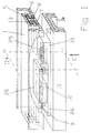
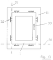
Fig.13 zeigt ein Fenster/eine Tür mit sogenanntem Dreh-Kipp-Flügel. Der Flügelrahmen 1 sitzt um eine untere horizontale Achse 30 kippbar oder um eine vertikale Drehachse 31 drehbar am Blendrahmen 11. Zur Festlegung der jeweiligen Drehachse sind sogenannte Schließpaarungen 32 zwischen Blendrahmen 11 und Flügelrahmen 1 vorgesehen. Jede dieser Schließpaarungen 32 besteht aus einzelnen Schließpartnern, von denen einer am Blendrahmen 11 und der andere Schließpartner am Flügelrahmen 1 sitzt. In Abhängigkeit von den jeweils in Eingriff befindlichen Schließpartnern wird daher entweder die horizontale Kippachse oder die vertikale Drehachse des Fensters/der Tür definiert. Welche der Schließpaarungen jeweils im Eingriff ist, wird über Drehung des Handgriffs 33 am Flügelrahmen in Verbindung mit einem an sich bekannten Dreh-Kipp-Beschlag vorgegeben.Fig. 13 shows a window / door with a so-called turn-tilt sash. The
Auf diese Weise gelangen in der Kippstellung die unten liegenden Schließpaarungen 32 im Eingriff, in der Drehstellung ist keine der Schließpaarungen im Eingriff, in der Schließstellung sind alle Schließpaarungen im Eingriff.In this way, in the tilted position, the
Die im Eingriff befindlichen Schließpaarungen 32 werden gebildet aus einem Pilzbolzen 9, der mit einem zugehörigen Einfahrschlitz 25 am jeweils anderen Rahmenteil zusammenwirkt. Dies geschieht dadurch, daß Pilzbolzen 9 und Einfahrschlitz 25 relativ zueinander in Längsrichtung des Einfahrschlitzes beweglich sind. Der Pilzbolzen 9 kann daher von der geöffneten Seite des Einfahrschlitzes 25 her in diesen einfahren. Dabei hintergreift das pilzkopfartig verdickte Ende des Pilzbolzens 9 den Einfahrschlitz 25 derart, daß der Flügelrahmen 1 beim Versuch des Aufhebelns über die zugfeste Verbindung zwischen Pilzbolzen 9 und Einfahrschlitz 25 zuverlässig gehalten wird.The
Wesentlich ist also, daß zwischen Flügelrahmen 1 und Blendrahmen 11 eine zusammenhängende Zugverbindung geschaffen wird, die insbesondere in der Kippstellung verhindert, daß der Flügelrahmen 1 aus seiner vorgegebenen Position am Blendrahmen 11 herausgehebelt werden kann.It is therefore essential that a coherent train connection is created between the
Dies ist zwar an sich bekannt, (siehe EP 94 107 819).This is known per se (see EP 94 107 819).
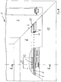
Von Besonderheit ist jedoch das spezielle Zusammenwirken der Schließpartner, worauf im folgenden an Hand der Fig.1 bis 3 zunächst eingegangen wird. Insbesondere Fig.1 zeigt einen Ausschnitt aus einem Fenster/einer Tür. Der gesamte Rahmen wird von Kunststoffhohlprofilen gebildet. Zumindest der Blendrahmen 11 zeigt zusätzlich eine Metallverstärkung 34 welche in einen Hohlraum des Blendrahmen 11 durchgehend eingesteckt ist. Auf der Falzluftseite 35 des Blendrahmens 11 ist ein sogenanntes Schließstück 10 angebracht und fest mit dem Blendrahmen 11 verbunden. Hierbei ist das Schließstück 10 vorteilhaft mit durchgängigen Schrauben gegen den Blendrahmen 11 verschraubt, wobei die Schrauben insbesondere auch die Metallverstärkung 34 durchdringen und auf diese Weise das Schließstück 10 fest am Blendrahmen 11 verankern. Demgegenüber weist hier der Flügelrahmen 1 die Beschlagnut 5 auf. In der Beschlagnut 5 ist der Fensterbeschlag 6 eingelegt. Derartiger Fensterbeschlag 6 besteht aus einer Deckschiene 7 sowie einer längs der Deckschiene 7 gleitend geführten Treibstange 8. Die Treibstange 8 wird, was an sich bekannt ist, über den Handgriff 33 in Bewegung gesetzt und dabei entlang der Deckschiene 7 verfahren. Die Treibstange 8 treibt wiederum einen Schließpartner 12, welcher dem Schließstück 10 zugeordnet ist. Der Schließpartner 12 ist daher starr mit der Treibstange 8 verbunden. Zu diesem Zweck weist die Deckschiene 7 im Verbindungsbereich zwischen Schließpartner 12 und Treibstange 8 Langlöcher 37 auf. Diese Langlöcher 37 werden von Treibstangenbolzen 36 durchsetzt. Auf diese Weise entsteht zwischen der Treibstange 8 und dem Schließpartner 12 an der Treibstange eine starre Verbindung, mittels welcher der Schließpartner synchron und gleich gerichtet mit der Treibstange 8 bei Betätigung des Handgriffs 33 verfahren wird. Zur zusätzlichen Befestigung des Beschlages 6 am Flügelrahmen 1 dient hier die Sicherungsplatte 13, welche sich in geeigneter Weise hinter der Beschlagnut 5 gegen den Flügelrahmen 1 abstützt. Hierauf wird noch eingegangen. Zumindest ist jedoch die Sicherungsplatte 13 so angeordnet, daß sie die Beschlagnut 5 hintergreift. Wesentlich ist aber auch, daß in Abhängigkeit von den tatsächlichen Einbauverhältnissen zwischen Flügelrahmen 1 und Blendrahmen 11 eine Sicherungsplatte 13 nicht unbedingt erforderlich ist. Die Verwendung der Sicherungsplatte 13 schafft aber jedenfalls zusätzliche Sicherheit gegen Aufhebeln des Flügelrahmens 1. Hierauf wird noch eingegangen werden.However, what is special is the special interaction of the locking partners, which will be discussed in the following with reference to FIGS. 1 to 3. 1 shows a section of a window / door. The entire frame is made of hollow plastic profiles. At least the
Wesentlich ist nun die spezielle Ausbildung der Schließpaarungen allein oder vorzugsweise in Kombination mit der Befestigung des Beschlags am Flügelrahmen mittels Sicherungsplatte 13.What is essential now is the special design of the locking pairings alone or preferably in combination with the fastening of the fitting to the sash frame by means of a securing
Hierzu ist vorgesehen, daß von den Schließpartnern 10,12 der Schließstellung und der Kippstellung zumindest einer der Schließpartner 12 mit Einfahrschlitz 25 starr mit der Treibstange 8 des Beschlags 6 verbunden ist. Dieser Schließpartner weist einen zugeordneten Pilzbolzen 9 am Blendrahmen 11 auf. Einfahrschlitz 25 und Pilzbolzen 9 sind relativ zueinander beweglich, um den Pilzbolzen mit seinem Hut den hinterschnittenen Bereich des Einfahrschlitzes 25 entweder in der Schließstellung oder in der Kippstellung hintergreifen zu lassen.For this purpose, it is provided that of the locking
Bereits durch diesen Hintergriff wird das Aufhebeln des Flügelrahmens auch in der Kippstellung erheblich erschwert, da hierzu der Beschlag aus seiner hierfür vorgesehenen Beschlagnut 5 des Flügelrahmens herauszureißen wäre.This rear grip alone makes it considerably more difficult to pry open the sash even in the tilted position, since for this purpose the fitting would have to be torn out of its
Darin liegt ein wesentlicher Aspekt der Erfindung. Der Schließpartner mit Einfahrschlitz muß sich über eine relativ große Länge am Beschlag erstrecken, zumindest mit der Länge des Einfahrschlitzes 25. Der Schließpartner mit Einfahrschlitz 25 ist mit der Treibstange 8 des Beschlags 6 verbunden, vorzugsweise flach gegen die Deckschiene angelegt. Die große Erstreckungslänge dieses Schließpartners 12 entlang der Deckschiene 7 verstärkt den Beschlag 6 in diesem Bereich zusätzlich, da der betreffende Schließpartner 12 an der Treibstange 8 sitzt und zusätzlich als Längsverstärkung der Treibstange 8 wirkt. Infolge der Verdickung der Treibstange 8 an dieser Stelle unter Zwischenlage der Deckschiene 7 über die Länge zumindest des Einfahrschlitzes 25 wird der Beschlag 6 zusätzlich biegesteif verstärkt.This is an essential aspect of the invention. The locking partner with the insertion slot must extend over a relatively large length on the fitting, at least the length of the
Im Bereich dieser Längsverstärkung der Treibstange 8 soll, in Weiterbildung der Erfindung, auch die hintergreifende Sicherungsplatte 13 angeordnet sein. Es ergibt sich daher eine großflächige Verteilung der Abstützkräfte von der Sicherungsplatte 13 auf die hintergriffenen Zonen des Flügelrahmens 1, so daß immense Gewalteinwirkung notwendig ist, um diese Hintergreifzone zu zerstören.In the area of this longitudinal reinforcement of the
Um diese Möglichkeit zu erschweren, kann daher zusätzlich vorgesehen sein, daß der Beschlag, bestehend aus Treibstange 8 und Deckschiene 7, zumindest im Längsbereich des an ihm befestigten Schließpartners 12 mit Einfahrschlitz 25 mittels einer die Beschlagnut 5 hintergreifenden Sicherungsplatte 13 gehalten wird. Diese Sicherungsplatte 13 hintergreift das Kunststoffprofil des Flügelrahmens 1 und ist in Richtung zum Blendrahmen 11 entweder mit der Treibstange 8 oder mit der Deckschiene 7 des Beschlags 6 verbunden. Auf diese Weise kann sich die Sicherungsplatte 13 im hintergreifenden Bereich an dem Flügelrahmen 1 abstützen, sofern beim Aufhebeln des Flügelrahmens 1 die hintergreifende Paarung Pilzbolzen-Einfahrschlitz (9-25) in Zugrichtung belastet wird. Daher bildet der so angeschlagene Flügelrahmen 1 eine baulich nur unter äußerster Gewalt zu trennende Einheit mit dem Blendrahmen 11. Wesentlicher Aspekt für den besten Aufhebelschutz ist daher die Kombination aus einem oder mehreren Schließpartnern 12 mit Einfahrschlitz 25 am Flügelrahmen 1 und dahinterliegender Anordnung der hintergreifenden Sicherungsplatte 13 derart, daß Treibstange 8 und Deckschiene 7 des Beschlags nicht nur mittels der Sicherungsplatte 13 gegen Herausziehen aus der Beschlagnut geschützt sind, sondern auch infolge des flach angefügten Schließpartners 12 mit Einfahrschlitz 25 weitgehend gegen Durchbiegung gesichert.To complicate this possibility, it can therefore additionally be provided that the fitting, consisting of
Prinzipiell kann die Sicherungsplatte 13 jeden Bereich des Flügelrahmens 1 hintergreifen. Vorteilhaft jedoch soll ein Vorsprung der Beschlagnut 5 hintergriffen werden. Dies bietet den Vorteil, daß an sich bekannte Kunststoffprofile ohne notwendige Abänderung weiter verwendbar sind.In principle, the securing
Die Fig.1 und 4 stimmen dahingehend überein, daß dort Einfahrschlitz 25 und Pilzbolzen 9 erhaben an der Treibstange 8 sitzen. Sie bilden ein sogenanntes erstes Schließteil. Zu diesem Zweck sind Einfahrschlitz 25 und Pilzbolzen 9 auf einer gemeinsamen Verbindungsplatte 26 angeordnet. Die Verbindungsplatte 26 liegt mit ihrer flachen Rückenfläche 27 dicht an der Gegenfläche der benachbarten Deckschiene 7 und wird über die in Fig.3 gezeigten und bereits beschriebenen Treibstangenbolzen 36 zusammen mit der Treibstange 8 verfahren. Einfahrschlitz 25 und Pilzbolzen 9 an der Treibstange 8 sind ein weiterer Pilzbolzen 9 sowie ein zugehöriger Einfahrschlitz 25 am Blendrahmen 11 zugeordnet. Letztere beiden Schließelemente sitzen auf einer weiteren Verbindungsplatte 26 und bilden das sogenannte zweite Schließteil. Folglich ist jeweils eines der Schließteile fest mit dem Beschlag 6 und das andere der Schließteile fest mit dem Blendrahmen 11 verbunden. In jedem Fall muß zusätzlich Einfahrschlitz 25 und Pilzbolzen 9 des einen Schließteils (4 des ersten Schließteils an der Treibstange) zwischen dem Einfahrschlitz und dem Pilzbolzen des anderen Schließteils (4 des zweiten Schließteils am Blendrahmen) angeordnet sein und zwischen zwei Endstellungen verfahrbar sein. In jeder der beiden Endstellungen greift das erste Schließteil an der Treibstange in das zweite Schließteil am Blendrahmen ein. Eine dazwischen liegende Mittelstellung, gezeigt in Fig.1,4, ist für erstes und zweites Schließteil ohne Eingriff. In dieser Mittelstellung läßt sich daher der Flügelrahmen 1 gegenüber dem Blendrahmen 11 öffnen.1 and 4 correspond in that the
Die Fig.5 und 6 zeigen weitere Ausführungsformen. In beiden Fällen weist das Schließteil 12, welches mit der Treibstange 8 verbunden ist, einen seitlichen geöffneten Schlitz 28 auf, in welchen der Pilzbolzen 9, der starr mit dem Blendrahmen 11 verbunden ist, seitlich einfahren kann. Nachdem der Pilzbolzen 9 um ein gewisses Maß in den seitlichen Schlitz 28 eingefahren ist, erreicht er eine Längsebene im zugehörigen Schließstück 12. Beidseits des Seitenschlitzes 28 erstreckt sich in dieser Längsebene zu beiden Längsrichtungen des Beschlags 6 der Einfahrschlitz 25, wie oben beschrieben. Befindet sich das Schließstück 12, welches mit der Treibstange 8 verbunden ist, in der gezeigten Mittelstellung, kann daher der Flügelrahmen 1 gegenüber dem Blendrahmen 11 geöffnet oder verschlossen werden. Ist der Flügelrahmen 1 geschlossen, wird anschließend über den Handgriff 33 die Treibstange 8 in Bewegung gesetzt. Dabei wird das Schließstück 12 entsprechend angetrieben und der zugehörige Pilzbolzen 9 am Blendrahmen 11 kann in den zugeordneten Einfahrschlitz 25 einfahren.5 and 6 show further embodiments. In both cases, the closing
Der Unterschied zwischen Fig.5 und 6 besteht darin, daß im Falle der Fig.5 lediglich ein Pilzbolzen vorgesehen ist. Dieser Pilzbolzen wirkt daher mit jeweils einem anderen Einfahrschlitz 25 zusammen, und zwar abhängig von der Drehstellung oder der Kippstellung des Flügelrahmens 1. Hiervon abweichend zeigt Fig.6, daß zwei Pilzbolzen vorgesehen sind, die wiederum auf einer gemeinsamen Verbindungsplatte 26 angeordnet werden. In diesem Fall wirkt jeweils nur ein Pilzbolzen entweder für die Schließstellung des Fensterflügels oder für die Kippstellung. Der seitliche Schlitz 28 muß allerdings entsprechend breiter sein. Hieraus ergibt sich auch der Vorteil, daß das Schließstück 12 am Flügelrahmen mit entsprechend größerer Kontaktfläche an den Beschlag 6 angefügt ist. Daher wird der Beschlag 6 zusätzlich gegen Durchbiegung verstärkt.The difference between Figures 5 and 6 is that only one mushroom pin is provided in the case of Figure 5. This mushroom bolt therefore interacts with a
Weiterhin zeigt Fig.7, daß an der Treibstange 8 ein Schließteil 12 angebracht sein kann, welches zwei nach außen endseitig offene Einfahrschlitze 25 besitzt. In diesem Fall ist mit dem Blendrahmen 11 ein Pilzbolzenpaar 9 starr verbunden. Jeweils einer der Pilzbolzen wirkt in der Schließstellung und der andere Pilzbolzen in der Kippstellung mit einem der Einfahrschlitze zusammen. Um auch hier zu einer erhöhten Stabilität zu kommen, wird vorgeschlagen, beide Pilzbolzen 9 auf gemeinsamer Verbindungsplatte 26 anzuordnen.7 also shows that a closing
Wie bereits erwähnt, wird bereits durch die relativ große Auflagefläche zwischen Schließstück 12 und dem Beschlag 6 einer gewaltsamen Durchbiegung des Beschlags entgegengewirkt. Zusätzliche Sicherheit kann daher noch durch die Sicherungsplatte 13 geschaffen werden. Im folgenden wird auf diesen Sachverhalt noch genauer eingegangen.As already mentioned, the relatively large contact area between the
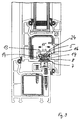
Die folgenden Fig.8 bis 12 zeigen einen Flügelrahmen, wie er beispielsweise für Fenster oder Türen bekannt ist. Derartiger Flügelrahmen 1 besteht aus Rahmenholmen 2,3 die im Bereich von Gehrungsstellen 4 rechtwinklig zusammengesetzt sind. Üblicherweise sind derartige Rahmenholme aus Kunststoffprofilen gefertigt, dies jedoch ohne Einschränkung der Erfindung auf Kunststoffprofile. Es gibt derartige Flügelrahmen, wie an sich bekannt, auch aus Holz. Weiterhin sind derartige Holzrahmen bekannt geworden, bei denen die Beschlagnut 5 (siehe Fig.9) aus einem Kunststoffeinsatz besteht, der mit dem Material des Flügelrahmens fest verschraubt ist.The following Fig. 8 to 12 show a casement, as is known for example for windows or doors.
Wie man an Hand von Fig.1 bis 3 bzw. Fig.8,9 erkennt, bildet die Beschlagnut 5 eine längsverlaufende Materialausnehmung an dem Flügelrahmen 1. Die Beschlagnut 5 weist dabei zwei sich gegenüberliegende Vorsprünge 14 auf, welche den engsten Querschnitt der Beschlagnut 5 definieren. In Richtung zur Glasseite des Flügelrahmens erweitert sich die Beschlagnut 5 hinter den Vorsprüngen 14 und bildet somit einen hinterschnittenen Bereich.As can be seen from FIGS. 1 to 3 and 8.9, the
Wie an sich bekannt ist, dient die Beschlagnut 5 zur Aufnahme eines Fensterbeschlags 6. Derartiger Fensterbeschlag 6 besteht aus einer Deckschiene 7 und einer daran längsgeführten Treibstange 8. Üblicherweise wird die Deckschiene 7 mittels Schrauben durch entsprechende Langlöcher in der Treibstange 8 am Grunde der Beschlagnut 5 verschraubt und gegenüber dem Flügelrahmen gehalten. Wie man weiterhin erkennt, ist mit der Treibstange 8 fest verbunden sogenannter Pilzbolzen 9. Es können auch paarweise Pilzbolzen vorgesehen sein (siehe EP 0 628 691), und zwar ein Pilzbolzen für die Schließstellung und ein Pilzbolzen für die Kippstellung des Flügelrahmens. Das zugeordnete Schließstück 10 weist hierzu jeweils entsprechende Längsausnehmungen auf, in welche die Pilzbolzen mit ihrem Stielbereich einfahren, so daß die erweiterten Bereiche der Pilzbolzen diese Einfahrschlitze hintergreifen und ein Aushebeln des Flügelrahmens so verhindert wird. Wie bereits erwähnt, kann die Deckschiene 7 mittels geeigneter Schrauben in der Beschlagnut 5 fixiert sein. Speziell ist hier als Aufbruchsicherung vorgesehen, daß Deckschiene 7 und Treibstange 8 mittels einer den Vorsprung 14 der Beschlagnut 5 hintergreifenden Sicherungsplatte 13 am Flügelrahmen gehalten werden und daß die Beschlagnut 5 eine außerhalb des Haltebereichs 23 liegende Eintrittsöffnung 20 für die Sicherungsplatte 13 aufweist. Zusätzlich ist der Sonderfall gezeigt, daß die Sicherungsplatte 13 lediglich im Längsbereich 12 des Schließpartners an der Treibstange 8 vorgesehen ist.As is known per se, the
Hieraus ergibt sich der Vorteil, daß der hintergreifende Bereich des Pilzbolzen 9 am Schließstück 10, und somit die Fixierung des Pilzbolzen gegenüber dem Blendrahmen 11 ein unmittelbar benachbartes und damit entsprechend stabiles Widerlager am Flügelrahmen 1 erhält. Während nämlich einerseits das Schließstück 10 fest mit dem Blendrahmen 11 verbunden ist, so daß der erweiterte Bereich des Pilzbolzens 9 aufbruchsicher mit dem Blendrahmen 11 in Verbindung gehalten wird, erfolgt die entsprechende Gegenlagerung des Fensterbeschlages 6 durch die Sicherungsplatte 13, welche die Vorsprünge 14 der Beschlagnut 5 aufbruchsicher hintergreift.This results in the advantage that the area behind the
Hierzu nimmt der erweiterte Bereich 15 der Beschlagnut 5 die Sicherungsplatte 13 auf, deren Breite 16 größer als die durch die Vorsprünge 14 verringerte Breite 15 der Beschlagnut 5 ist.For this purpose, the
Bei einem etwaigen Aufbruchversuch stemmt sich daher die Sicherungsplatte 13 fest gegen die Vorsprünge 14 und verhindert so ein Ausziehen des Fensterbeschlages 6 im aufbruchempfindlichen Fenstereckbereich.In the event of a possible attempt to break open, the securing
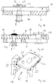
Wie Fig.10 und 11 erkennen lassen, kann einerseits die Sicherungsplatte 13 fest mit der Treibstange 8 verbunden sein. Sie macht dann die Längsbewegung der Treibstange 8 innerhalb des erweiterten Bereichs 15 der Beschlagnut 5 mit und ist zu diesem Zweck mit Bewegungsspiel in Längsrichtung innerhalb der Beschlagnut 5 gelagert. Hiervon abweichend zeigt Fig.11 daß die Sicherungsplatte 13 mittels Bolzen 17 fest mit der Deckschiene 7 verbunden ist. Der Bolzen 17 durchbricht die Treibstange 8 in dem Bereich eines Langlochs 19, so daß die Treibstange 8 ungehindert von der Befestigung der Sicherungsplatte 13 beweglich ist. Diese Variante bietet den Vorteil, daß zum Herausbrechen des Fensterbeschlags 6 zusätzliche Gewalt aufgewandt werden muß, um Deckschiene 7 zusammen mit Treibstange 8 zu zerstören. Der wesentliche Vorteil dieser Ausführung besteht darin, daß bei einem etwaigen Aufbruchversuch Deckschiene 7 und Treibstange 8 gegeneinander verpreßt werden und praktisch eine unzerstörbare Einheit bilden. Diese Einheit kann praktisch nur über unmögliche Zerstörung der Bolzen 17,17a für Sicherungsplatte bzw. Pilzbolzen aufgebrochen werden.As can be seen in FIGS. 10 and 11, on the one hand the securing
Wie weiterhin die Figuren erkennen lassen, ist der Bolzen 17 mit seinem Bolzenkopf 18 in der Sicherungsplatte 13 in einer Versenkung 24 gelagert, so daß die Oberseite der Sicherungsplatte 13 in Höhenrichtung zur Beschlagnut mit Spiel geführt ist, was Führigkeit und Leichtgängigkeit ermöglicht.As can also be seen from the figures, the
Zusätzlich zeigt Fig.8, daß die Eintrittsöffnung 20 für die Sicherungsplatte 13 endseitig des Rahmenholms 2 durch eine Materialausnehmung erstellt wird. Im vorliegenden Fall ist die Eintrittsöffnung 20 im Bereich der Gehrungsstelle 4 angeordnet, dies jedoch ohne Einschränkung der Erfindung. Zu diesem Zweck bedarf es lediglich einer Einfräsung des Gehrungsbereichs 4 dort wo die Beschlagnuten der Rahmenholme 2,3 aufeinander stoßen. Zwangsläufig ergibt sich somit endseitig des Rahmenholms 2 die Eintrittsöffnung 20 für den erfindungsgemäßen Fensterbeschlag 6.In addition, FIG. 8 shows that the entry opening 20 for the securing
Zusätzlich zeigt Fig.12 eine Sicherungsplatte 13, die an zwei ihrer gegenüberliegenden Längskanten 21 mit einer in Richtung zum Vorsprung 14 weisenden Verzahnung 22 ausgestattet ist. Mittels dieser Verzahnung krallt sich die Sicherungsplatte 13 beim Aufbruchversuch hinter den Vorsprung 14 und erzielt somit eine zusätzliche Gegenkraft, die der Aufbruchrichtung entgegenwirkt.In addition, FIG. 12 shows a securing
Um den Effekt der flächigen Abstützung zwischen dem Schließpartner mit Einfahrschlitz an der Treibstange 8 und der Treibstange zu erzielen, und um auf diese Weise die Durchbiegung der Treibstange beim Aushebeln des Flügelrahmens zu erschweren, können mehrere Variationen zur Anwendung kommen.In order to achieve the effect of the flat support between the locking partner with an insertion slot on the
Hierzu zeigen Fig.1 bis 7, daß Einfahrschlitz 25 und Pilzbolzen 9 an jeweils einem einzigen Schließteil vorgesehen sind. Dieses Schließteil 12 ist starr mit der Treibstange 8 verbunden. Es handelt sich dabei um ein längs der Treibstange 8 angeordnetes Bauteil. Dieses Bauteil weist sowohl einen Einfahrschlitz 25 als auch einen gegenüberliegenden Pilzbolzen 9 auf. Das Bauteil kann beispielsweise aus Chrom-Nickel-Stahl oder ähnlich zähem Werkstoff gefertigt sein.1 to 7 show that the
Das zugeordnete Schließteil 10 am Blendrahmen 11 weist auf derjenigen Seite, welche dem Einfahrschlitz 25 des Schließteils 12 an der Treibstange 8 zugewandt ist, einen Pilzbolzen 9 auf, während das gegenüberliegende Ende des Schließteils 10 am Blendrahmen 11 mit einem für den Pilzbolzen 9 am Beschlag 6 vorgesehenen Einfahrschlitz 25 versehen ist. Innerhalb der lichten Weite zwischen Pilzbolzen 9 und Einfahrschlitz 25 des Schließteils 10 am Blendrahmen 11 ist das zugeordnete Schließteil 12 an der Treibstange 8 verfahrbar derart, daß entweder die rechte Schließpaarung, die linke Schließpaarung oder keine Schließpaarung in Eingriff ist. Diese drei Positionen entsprechen der Schließstellung des Fensters, der Offenstellung des Fensters, der Kippstellung des Fensters. Abweichend hiervon zeigt Fig.5, daß auch vorgesehen sein kann, lediglich einen Pilzbolzen am Blendrahmen 11 anzuschlagen. Hierzu kann ggf. eine Basisplatte 26 dienen, um auch am Blendrahmen 11 eine hinreichend große Auflagefläche zu erhalten. In diesem Falle wird zusätzlich vorgeschlagen, daß das Schließteil 12 der Treibstange 8 einen zentralen Einfahrschlitz 25 aufweist, von dem aus sich in jeweils einer Längsrichtung zur Treibstange 8 ein in Eingriff mit dem Pilzbolzen 9 kommender Einfahrschlitz 25 erstreckt. Auch hier sind drei Stellungen vorgesehen:
Entweder ist der Pilzbolzen 9 mit dem rechten Einfahrschlitz 25 in Eingriff, in der mittleren Stellung ungehindert aus dem Schließteil 12 herausfahrbar, in der linken Endstellung mit dem anderen Einfahrschlitz 25. Auf diese Weise sind wiederum die Schließstellung, die Offenstellung, die Kippstellung des Fensterflügels realisiert und trotzdem in der Schließstellung und in der Kippstellung eine zugfeste und aufhebelsichere Verbindung zwischen Flügelrahmen und Blendrahmen 11.The associated locking
Either the
Fig.6 zeigt als weiteres Ausführungsbeispiel die Anordnung zweier Pilzbolzen 9 am Blendrahmen 11. Die Pilzbolzen 9 spannen zwischen sich einen gewissen Abstand auf. Innerhalb dieses Abstandes ist ein Schließstück am Beschlag bzw. an der Treibstange 8 des Beschlags derart verfahrbar, daß dieser Beschlag mit seinen nach außen geöffneten Enden entweder in jeweils einen der Pilzbolzen eingefahren ist oder in der zentralen Stellung relativ zu den Pilzbolzen herausfahrbar ist. Die Funktion dieser Schließstellenpaarung entspricht der vorangegangenen beschriebenen Funktion, bei Bedarf auch jeweils in Kombination mit einer die Beschlagnut hintergreifenden Sicherungsplatte 13 am Flügelrahmen. Auch bei diesem Ausführungsbeispiel kann vorgesehen sein, das Pilzbolzenpaar 9 auf einer gemeinsamen Befestigungsplatte 26 anzuordnen, welche mit großer Auflagefläche am Blendrahmen 11 zu befestigen ist.6 shows, as a further exemplary embodiment, the arrangement of two
Die Befestigung der Schließteile am Blendrahmen 11 kann in jedem Falle zweckmäßig durch Verschraubung mit dem bei derartigen Fenstern üblichen innenliegenden metallischen Verstärkungsteil erfolgen. Ggf. können auch, um die Ausziehsicherheit zusätzlich zu erhöhen, Schrauben mit erhöhten Gewindegängen vorgesehen sein. Bei derartigen Schrauben ist der Kerndurchmesser im Verhältnis zum Nenndurchmesser wesentlich kleiner, um diese Schrauben mit entsprechender Hintergreifzone am metallischen Verstärkungsprofil angreifen zu lassen.The fastening of the locking parts on the
Für die Erfindung kommt es wesentlich darauf an, daß zumindest einer der Schließpartner mit Einfahrschlitz an der Treibstange 8 des Beschlags angeordnet ist. Da derartige Einfahrschlitze eine vorbestimmte Länge des zugehörigen Schließteils bedingen, nämlich zumindest die Einfahrlänge, wird die Treibstange 8 des Beschlags in diesem Bereich überproportional gegen Durchbiegung verstärkt, wodurch mit Verwendung der entsprechenden hintergreifenden Sicherungsplatte 13 ein außerordentlich hoher Aufhebelschutz des Flügelrahmens erzielt wird.It is essential for the invention that at least one of the locking partners with an entry slot is arranged on the
- 11
- Flügelrahmen/FensterCasement / window
- 22nd
- RahmenholmFrame spar
- 33rd
- RahmenholmFrame spar
- 44th
- GehrungsstelleMiter point
- 55
- BeschlagnutHardware groove
- 66
- FensterbeschlagWindow fitting
- 77
- DeckschieneCover rail
- 88th
- TreibstangeConnecting rod
- 99
- PilzbolzenMushroom bolt
- 1010th
- SchließstückStriker
- 1111
- BlendrahmenFrame
- 1212th
- Längsbereich des Schließpartners an der TreibstangeLongitudinal area of the locking partner on the drive rod
- 1313
- SicherungsplatteLocking plate
- 1414
- Vorsprunghead Start
- 1515
- erweiterter Bereichextended area
- 1616
- Breite der SicherungsplatteWidth of the locking plate
- 1717th
- Bolzen für SicherungsplatteBolt for locking plate
- 17a17a
- Bolzen für PilzknopfBolt for mushroom button
- 1818th
- BolzenkopfBolt head
- 1919th
- Langloch in der TreibstangeElongated hole in the connecting rod
- 2020th
- EintrittsöffnungEntrance opening
- 2121
- LängskanteLong edge
- 2222
- VerzahnungGearing
- 2323
- HaltebereichStopping area
- 2424th
- VersenkungSinking
- 2525th
- EinfahrschlitzEntry slot
- 2626
- VerbindungsplatteConnecting plate
- 2727
- RückenflächeBack surface
- 2828
- seitlicher Schlitzside slit
- 3030th
- horizontale Kippachsehorizontal tilt axis
- 3131
- vertikale Drehachsevertical axis of rotation
- 3232
- SchließpaarungClosing pairing
- 3333
- HandgriffHandle
- 3434
- MetallverstärkungMetal reinforcement
- 3535
- FalzluftseiteAir side
- 3636
- TreibstangenbolzenEspagnolette bolts
- 3737
- LanglochLong hole
Claims (16)
Applications Claiming Priority (2)
| Application Number | Priority Date | Filing Date | Title |
|---|---|---|---|
| DE29513098U DE29513098U1 (en) | 1995-08-16 | 1995-08-16 | Window / door with turn-tilt fitting |
| DE29513098U | 1995-08-16 |
Publications (4)
| Publication Number | Publication Date |
|---|---|
| EP0761920A2 true EP0761920A2 (en) | 1997-03-12 |
| EP0761920A3 EP0761920A3 (en) | 1997-08-20 |
| EP0761920B1 EP0761920B1 (en) | 2000-01-05 |
| EP0761920B2 EP0761920B2 (en) | 2005-05-18 |
Family
ID=8011783
Family Applications (1)
| Application Number | Title | Priority Date | Filing Date |
|---|---|---|---|
| EP96112699A Expired - Lifetime EP0761920B2 (en) | 1995-08-16 | 1996-08-07 | Window/door with pivot and/or tilting fitting |
Country Status (4)
| Country | Link |
|---|---|
| EP (1) | EP0761920B2 (en) |
| AT (1) | ATE188530T1 (en) |
| DE (2) | DE29513098U1 (en) |
| DK (1) | DK0761920T3 (en) |
Cited By (4)
| Publication number | Priority date | Publication date | Assignee | Title |
|---|---|---|---|---|
| DE19625946C2 (en) * | 1996-06-28 | 1998-10-29 | Pax Gmbh | Combination of casement and window frame of a window / door |
| DE19739407A1 (en) * | 1997-09-09 | 1999-03-11 | Pax Gmbh | Window door |
| EP1405974A2 (en) * | 2002-10-01 | 2004-04-07 | Klaus Dipl.-Ing. Wöppel | Locking mechanism for turn and tilt window or door |
| EP2752307A1 (en) * | 2013-01-07 | 2014-07-09 | PaX AG | Glazing for a door or window |
Families Citing this family (3)
| Publication number | Priority date | Publication date | Assignee | Title |
|---|---|---|---|---|
| DE19534253A1 (en) * | 1995-09-15 | 1997-03-20 | Pax Gmbh | Window / door with locking points between the turn-tilt sash frame and the fixed window frame |
| DE102012200120A1 (en) * | 2011-01-12 | 2012-07-12 | Hautau Gmbh | Espagnolette fitting and working method for a narrow sash |
| DE102012202151A1 (en) * | 2012-02-13 | 2013-08-14 | Hautau Gmbh | Espagnolette fitting with gap ventilation and locking function |
Citations (5)
| Publication number | Priority date | Publication date | Assignee | Title |
|---|---|---|---|---|
| EP0012786A1 (en) * | 1978-12-27 | 1980-07-09 | Siegenia-Frank Kg | Window, door or the like composed of plastic profile members |
| GB2147657A (en) * | 1983-08-13 | 1985-05-15 | Rsb Holding & Management Ag | A single handle operated tilt or turn mounting for a window or the like |
| DE8614557U1 (en) * | 1986-05-30 | 1986-07-17 | Siegenia-Frank Kg, 5900 Siegen | Hooking device between the wing and the fixed frame of windows, doors or the like. |
| DE4009637A1 (en) * | 1989-07-06 | 1991-01-17 | Saelzer Sicherheitstechnik | Security device for casement window - consists of two overlapping ridges on rails fixed to moving and fixed frames of window |
| DE9308472U1 (en) * | 1993-06-07 | 1993-09-02 | Pax Schweikhard Gmbh | Turn-tilt hardware for windows, doors or the like. |
-
1995
- 1995-08-16 DE DE29513098U patent/DE29513098U1/en not_active Expired - Lifetime
-
1996
- 1996-08-07 EP EP96112699A patent/EP0761920B2/en not_active Expired - Lifetime
- 1996-08-07 DE DE59604096T patent/DE59604096D1/en not_active Expired - Lifetime
- 1996-08-07 DK DK96112699T patent/DK0761920T3/en active
- 1996-08-07 AT AT96112699T patent/ATE188530T1/en not_active IP Right Cessation
Patent Citations (5)
| Publication number | Priority date | Publication date | Assignee | Title |
|---|---|---|---|---|
| EP0012786A1 (en) * | 1978-12-27 | 1980-07-09 | Siegenia-Frank Kg | Window, door or the like composed of plastic profile members |
| GB2147657A (en) * | 1983-08-13 | 1985-05-15 | Rsb Holding & Management Ag | A single handle operated tilt or turn mounting for a window or the like |
| DE8614557U1 (en) * | 1986-05-30 | 1986-07-17 | Siegenia-Frank Kg, 5900 Siegen | Hooking device between the wing and the fixed frame of windows, doors or the like. |
| DE4009637A1 (en) * | 1989-07-06 | 1991-01-17 | Saelzer Sicherheitstechnik | Security device for casement window - consists of two overlapping ridges on rails fixed to moving and fixed frames of window |
| DE9308472U1 (en) * | 1993-06-07 | 1993-09-02 | Pax Schweikhard Gmbh | Turn-tilt hardware for windows, doors or the like. |
Cited By (7)
| Publication number | Priority date | Publication date | Assignee | Title |
|---|---|---|---|---|
| DE19625946C2 (en) * | 1996-06-28 | 1998-10-29 | Pax Gmbh | Combination of casement and window frame of a window / door |
| DE19739407A1 (en) * | 1997-09-09 | 1999-03-11 | Pax Gmbh | Window door |
| EP0902145A2 (en) | 1997-09-09 | 1999-03-17 | Pax GmbH | Window or door |
| DE19739407C2 (en) * | 1997-09-09 | 2001-05-17 | Pax Gmbh | Window door |
| EP1405974A2 (en) * | 2002-10-01 | 2004-04-07 | Klaus Dipl.-Ing. Wöppel | Locking mechanism for turn and tilt window or door |
| EP1405974A3 (en) * | 2002-10-01 | 2004-12-22 | Klaus Dipl.-Ing. Wöppel | Locking mechanism for turn and tilt window or door |
| EP2752307A1 (en) * | 2013-01-07 | 2014-07-09 | PaX AG | Glazing for a door or window |
Also Published As
| Publication number | Publication date |
|---|---|
| DE29513098U1 (en) | 1996-12-19 |
| EP0761920A3 (en) | 1997-08-20 |
| DK0761920T3 (en) | 2000-05-29 |
| EP0761920B2 (en) | 2005-05-18 |
| EP0761920B1 (en) | 2000-01-05 |
| ATE188530T1 (en) | 2000-01-15 |
| DE59604096D1 (en) | 2000-02-10 |
Similar Documents
| Publication | Publication Date | Title |
|---|---|---|
| EP0294630B1 (en) | Fastener for windows, doors, etc. | |
| EP0433623B1 (en) | Locking device for a window, a door or similar | |
| EP0761920B1 (en) | Window/door with pivot and/or tilting fitting | |
| DE19521601C1 (en) | Window, door or the like | |
| DE4218983C2 (en) | Window or door with fittings for installation in graduated profile grooves in the sash | |
| EP0733761B1 (en) | Wing frame | |
| EP0844348A1 (en) | Hinge for doors or windows | |
| EP3222801B1 (en) | Bolt mechanism with lock for containers for valuable goods | |
| AT505580B1 (en) | HOLDER-FREE WINDOW, DOOR OR DGL. | |
| DE4200868A1 (en) | Lock for window or door - has two parallel bolts actuated by lock handle | |
| EP0556442A1 (en) | Actuating rod fitting for doors, windows and the like | |
| DE19507481C1 (en) | Lockable window hasp with front body fixed to casement main body | |
| DE3215452A1 (en) | Corner deflection for espagnolette fittings of windows, doors or the like | |
| EP0128372A2 (en) | Device for fastening one wing of a pair of windows, doors or the like | |
| DE60201616T2 (en) | Lock for door, window, etc. with rod-like fitting | |
| EP0445432A2 (en) | Door or window fittings | |
| DE10229228A1 (en) | Door or window sash arrangement | |
| EP1045097A1 (en) | Fitting for a window and window comprising such a fitting | |
| WO2001055541A1 (en) | Drive rod fitting | |
| EP1659241B1 (en) | Burglar-proof fitting for a multi-light window or multi-leaf door | |
| EP0756054A2 (en) | Window, door or the like | |
| EP0276379B1 (en) | Fastening device for armatures | |
| EP0158069B1 (en) | Closing and latching arrangement for doors and the like | |
| EP1130200B1 (en) | Locking device | |
| DE19504419C2 (en) | Espagnolette fitting |
Legal Events
| Date | Code | Title | Description |
|---|---|---|---|
| PUAI | Public reference made under article 153(3) epc to a published international application that has entered the european phase |
Free format text: ORIGINAL CODE: 0009012 |
|
| AK | Designated contracting states |
Kind code of ref document: A2 Designated state(s): AT CH DE DK FR GB IT LI SE |
|
| PUAL | Search report despatched |
Free format text: ORIGINAL CODE: 0009013 |
|
| AK | Designated contracting states |
Kind code of ref document: A3 Designated state(s): AT CH DE DK FR GB IT LI SE |
|
| 17P | Request for examination filed |
Effective date: 19971111 |
|
| GRAG | Despatch of communication of intention to grant |
Free format text: ORIGINAL CODE: EPIDOS AGRA |
|
| 17Q | First examination report despatched |
Effective date: 19981123 |
|
| GRAG | Despatch of communication of intention to grant |
Free format text: ORIGINAL CODE: EPIDOS AGRA |
|
| GRAH | Despatch of communication of intention to grant a patent |
Free format text: ORIGINAL CODE: EPIDOS IGRA |
|
| GRAH | Despatch of communication of intention to grant a patent |
Free format text: ORIGINAL CODE: EPIDOS IGRA |
|
| GRAA | (expected) grant |
Free format text: ORIGINAL CODE: 0009210 |
|
| AK | Designated contracting states |
Kind code of ref document: B1 Designated state(s): AT CH DE DK FR GB IT LI SE |
|
| REF | Corresponds to: |
Ref document number: 188530 Country of ref document: AT Date of ref document: 20000115 Kind code of ref document: T |
|
| REG | Reference to a national code |
Ref country code: CH Ref legal event code: NV Representative=s name: E. BLUM & CO. PATENTANWAELTE Ref country code: CH Ref legal event code: EP |
|
| REF | Corresponds to: |
Ref document number: 59604096 Country of ref document: DE Date of ref document: 20000210 |
|
| ITF | It: translation for a ep patent filed |
Owner name: STUDIO TORTA S.R.L. |
|
| GBT | Gb: translation of ep patent filed (gb section 77(6)(a)/1977) |
Effective date: 20000307 |
|
| ET | Fr: translation filed | ||
| REG | Reference to a national code |
Ref country code: DK Ref legal event code: T3 |
|
| PGFP | Annual fee paid to national office [announced via postgrant information from national office to epo] |
Ref country code: SE Payment date: 20000807 Year of fee payment: 5 Ref country code: DK Payment date: 20000807 Year of fee payment: 5 |
|
| PGFP | Annual fee paid to national office [announced via postgrant information from national office to epo] |
Ref country code: GB Payment date: 20000809 Year of fee payment: 5 |
|
| PLBI | Opposition filed |
Free format text: ORIGINAL CODE: 0009260 |
|
| PLBQ | Unpublished change to opponent data |
Free format text: ORIGINAL CODE: EPIDOS OPPO |
|
| PLBI | Opposition filed |
Free format text: ORIGINAL CODE: 0009260 |
|
| PLBF | Reply of patent proprietor to notice(s) of opposition |
Free format text: ORIGINAL CODE: EPIDOS OBSO |
|
| 26 | Opposition filed |
Opponent name: SIEGENIA-FRANK KG Effective date: 20000925 |
|
| 26 | Opposition filed |
Opponent name: SCHUECO INTERNATIONAL KG Effective date: 20001004 Opponent name: SIEGENIA-FRANK KG Effective date: 20000925 |
|
| PLBF | Reply of patent proprietor to notice(s) of opposition |
Free format text: ORIGINAL CODE: EPIDOS OBSO |
|
| 29U | Proceedings interrupted after grant according to rule 142 epc |
Effective date: 20010501 |
|
| 29W | Proceedings resumed after grant [after interruption of proceedings according to rule 142 epc] |
Effective date: 20011116 |
|
| PG25 | Lapsed in a contracting state [announced via postgrant information from national office to epo] |
Ref country code: GB Free format text: LAPSE BECAUSE OF NON-PAYMENT OF DUE FEES Effective date: 20010807 Ref country code: DK Free format text: LAPSE BECAUSE OF NON-PAYMENT OF DUE FEES Effective date: 20010807 |
|
| PG25 | Lapsed in a contracting state [announced via postgrant information from national office to epo] |
Ref country code: SE Free format text: LAPSE BECAUSE OF NON-PAYMENT OF DUE FEES Effective date: 20010808 |
|
| PLBF | Reply of patent proprietor to notice(s) of opposition |
Free format text: ORIGINAL CODE: EPIDOS OBSO |
|
| GBPC | Gb: european patent ceased through non-payment of renewal fee |
Effective date: 20010807 |
|
| EUG | Se: european patent has lapsed |
Ref document number: 96112699.2 |
|
| PLBF | Reply of patent proprietor to notice(s) of opposition |
Free format text: ORIGINAL CODE: EPIDOS OBSO |
|
| REG | Reference to a national code |
Ref country code: DK Ref legal event code: EBP |
|
| PLBF | Reply of patent proprietor to notice(s) of opposition |
Free format text: ORIGINAL CODE: EPIDOS OBSO |
|
| PLBF | Reply of patent proprietor to notice(s) of opposition |
Free format text: ORIGINAL CODE: EPIDOS OBSO |
|
| PLAB | Opposition data, opponent's data or that of the opponent's representative modified |
Free format text: ORIGINAL CODE: 0009299OPPO |
|
| R26 | Opposition filed (corrected) |
Opponent name: SCHUECO INTERNATIONAL KG Effective date: 20001004 Opponent name: SIEGENIA-AUBI KG. Effective date: 20000925 |
|
| PGFP | Annual fee paid to national office [announced via postgrant information from national office to epo] |
Ref country code: AT Payment date: 20030813 Year of fee payment: 8 |
|
| PGFP | Annual fee paid to national office [announced via postgrant information from national office to epo] |
Ref country code: FR Payment date: 20030825 Year of fee payment: 8 |
|
| PGFP | Annual fee paid to national office [announced via postgrant information from national office to epo] |
Ref country code: CH Payment date: 20031013 Year of fee payment: 8 |
|
| PG25 | Lapsed in a contracting state [announced via postgrant information from national office to epo] |
Ref country code: AT Free format text: LAPSE BECAUSE OF NON-PAYMENT OF DUE FEES Effective date: 20040807 |
|
| PG25 | Lapsed in a contracting state [announced via postgrant information from national office to epo] |
Ref country code: LI Free format text: LAPSE BECAUSE OF NON-PAYMENT OF DUE FEES Effective date: 20040831 Ref country code: CH Free format text: LAPSE BECAUSE OF NON-PAYMENT OF DUE FEES Effective date: 20040831 |
|
| PUAH | Patent maintained in amended form |
Free format text: ORIGINAL CODE: 0009272 |
|
| STAA | Information on the status of an ep patent application or granted ep patent |
Free format text: STATUS: PATENT MAINTAINED AS AMENDED |
|
| REG | Reference to a national code |
Ref country code: CH Ref legal event code: PL |
|
| PG25 | Lapsed in a contracting state [announced via postgrant information from national office to epo] |
Ref country code: FR Free format text: LAPSE BECAUSE OF NON-PAYMENT OF DUE FEES Effective date: 20050429 |
|
| 27A | Patent maintained in amended form |
Effective date: 20050518 |
|
| AK | Designated contracting states |
Kind code of ref document: B2 Designated state(s): AT CH DE DK FR GB IT LI SE |
|
| REG | Reference to a national code |
Ref country code: FR Ref legal event code: ST |
|
| PG25 | Lapsed in a contracting state [announced via postgrant information from national office to epo] |
Ref country code: IT Free format text: LAPSE BECAUSE OF NON-PAYMENT OF DUE FEES Effective date: 20050807 |
|
| EN | Fr: translation not filed | ||
| PLAB | Opposition data, opponent's data or that of the opponent's representative modified |
Free format text: ORIGINAL CODE: 0009299OPPO |
|
| REG | Reference to a national code |
Ref country code: DE Ref legal event code: R082 Ref document number: 59604096 Country of ref document: DE Representative=s name: MUELLER, JOCHEN, DIPL.-ING., DE Ref country code: DE Ref legal event code: R082 Ref document number: 59604096 Country of ref document: DE Representative=s name: JOCHEN MUELLER, DE |
|
| PGFP | Annual fee paid to national office [announced via postgrant information from national office to epo] |
Ref country code: DE Payment date: 20150820 Year of fee payment: 20 |
|
| REG | Reference to a national code |
Ref country code: DE Ref legal event code: R071 Ref document number: 59604096 Country of ref document: DE |