EP0733761B1 - Wing frame - Google Patents
Wing frame Download PDFInfo
- Publication number
- EP0733761B1 EP0733761B1 EP96103709A EP96103709A EP0733761B1 EP 0733761 B1 EP0733761 B1 EP 0733761B1 EP 96103709 A EP96103709 A EP 96103709A EP 96103709 A EP96103709 A EP 96103709A EP 0733761 B1 EP0733761 B1 EP 0733761B1
- Authority
- EP
- European Patent Office
- Prior art keywords
- mounting groove
- retaining plate
- frame according
- mushroom
- casement
- Prior art date
- Legal status (The legal status is an assumption and is not a legal conclusion. Google has not performed a legal analysis and makes no representation as to the accuracy of the status listed.)
- Expired - Lifetime
Links
Images
Classifications
-
- E—FIXED CONSTRUCTIONS
- E05—LOCKS; KEYS; WINDOW OR DOOR FITTINGS; SAFES
- E05C—BOLTS OR FASTENING DEVICES FOR WINGS, SPECIALLY FOR DOORS OR WINDOWS
- E05C9/00—Arrangements of simultaneously actuated bolts or other securing devices at well-separated positions on the same wing
- E05C9/004—Faceplates ; Fixing the faceplates to the wing
-
- E—FIXED CONSTRUCTIONS
- E05—LOCKS; KEYS; WINDOW OR DOOR FITTINGS; SAFES
- E05B—LOCKS; ACCESSORIES THEREFOR; HANDCUFFS
- E05B17/00—Accessories in connection with locks
- E05B17/20—Means independent of the locking mechanism for preventing unauthorised opening, e.g. for securing the bolt in the fastening position
- E05B17/2084—Means to prevent forced opening by attack, tampering or jimmying
-
- E—FIXED CONSTRUCTIONS
- E05—LOCKS; KEYS; WINDOW OR DOOR FITTINGS; SAFES
- E05C—BOLTS OR FASTENING DEVICES FOR WINGS, SPECIALLY FOR DOORS OR WINDOWS
- E05C9/00—Arrangements of simultaneously actuated bolts or other securing devices at well-separated positions on the same wing
- E05C9/18—Details of fastening means or of fixed retaining means for the ends of bars
- E05C9/1825—Fastening means
- E05C9/1833—Fastening means performing sliding movements
- E05C9/185—Fastening means performing sliding movements parallel with actuating bar
Definitions
- the invention relates to a casement frame with a recessed undercut fitting groove for receiving the cover rail and drive rod of a window fitting, the drive rod engaging behind an associated striker on the frame by means of a mushroom button.
- a sash frame is known from EP 628 691.
- guided deflection devices are located in the corner areas, e.g. elastic springs, with the help of which the adjoining ends of the fittings arriving there are coupled.
- the advantage of the invention is that the position of the mushroom button on the wing is kept as long as possible when trying to break open.
- the securing plate forms an anchoring of the drive rod on the sash frame, which interacts with the anchoring of the mushroom button on the associated striker and in that way an essentially rigid connection is created between the frame and the sash frame.
- the mushroom button engages behind its associated locking piece and the locking plate the projection of the fitting groove. While the striker is attached to the frame and the securing plate to the casement, a break-proof connection between casement and frame is created in this way, which can only be destroyed under extreme force. In this case, either the rear zone of the mushroom button on the striker or the rear zone of the locking plate in the hardware groove would have to be broken open. By appropriate dimensioning, however, the areas behind each mushroom button / striker and locking plate / hardware groove can be designed so stably that premature destruction of one of the two engagement zones is effectively countered.
- the invention can be implemented in various ways.
- the securing plate On the one hand, it is conceivable to firmly connect the securing plate to the drive rod and with play within the hardware groove. In this case, the securing plate also performs the longitudinal back and forth movement of the drive rod, but in the event of an attempt to break open, it nevertheless acts as a safeguard against the fitting being pulled out of the fitting groove. It is preferably placed directly on the mushroom bolt, so that an unbreakable, tensile connection between the frame and sash is created.
- the securing plate can also be firmly connected to the cover rail, preferably by means of a rigid bolt.
- the rigid bolt break through the drive rod in the region of an elongated hole, so that the drive rod can move freely.
- the locking plate according to this invention in the end area of the respective fitting, there is the further advantage of securing the fitting on the sash frame at the corner.
- the sash frame corner areas which are at great risk of burglary can be reliably secured in this way.
- the rear locking plate can be made so stable by the arrangement in the local area of the mushroom button or immediately next to it that the entire fitting only has to be held in the end area and is still secured against break-in.
- the entry opening for the securing plate in the fitting groove at the end of the frame spar offers the additional advantage of simple fitting of the fitting.
- the securing plate can also be rotatable with an essentially rectangular plan. Then the locking plate could be inserted into the fitting groove in the appropriate rotational position with the wide rectangle side parallel to the longitudinal direction of the fitting groove and then turned so far that the wide rectangle side is then perpendicular to the lengthwise direction of the fitting and engages behind the projection of the fitting groove.
- the entry opening is formed by the hardware groove itself.
- an insertion opening for the securing plate be provided in the area of the miter joint of two mutually abutting frame bars (e.g. by milling). This has the advantage that there is always a precisely defined position of the inlet opening, but this has no effect on the desired strength.
- the assembly can be simplified in that the securing plate is non-rotatably rigidly connected to the drive rod or cover rail, so that the appropriately designed window fitting is simply inserted into the entry opening of the fitting groove and moved longitudinally.
- FIG. 2 The figures show a casement, as is known for example for windows or doors.
- sash 1 consists of frame spars 2, 3 which are assembled at right angles in the area of miter points 4.
- frame spars are usually made of plastic profiles, but without restricting the invention to plastic profiles.
- sash frames are also made of wood.
- wooden frames of this type have become known in which the fitting groove 5 (see FIG. 2) consists of a plastic insert which is screwed to the material of the casement.
- the fitting groove 5 forms a longitudinal material recess from the casement.
- the fitting groove 5 has two mutually opposite projections 14, which define the narrowest cross section of the fitting groove 5.
- the hardware groove extends behind the projections and thus forms an undercut area.
- the fitting groove 5 serves to receive a window fitting 6.
- a window fitting 6 consists of a cover rail 7 and a drive rod 8 which is guided longitudinally thereon.
- the cover rail 7 is usually fastened by means of corresponding elongated holes in the drive rod 8 at the base of the fitting groove 5 screwed and held opposite the casement.
- so-called mushroom button 9 is firmly connected to the drive rod 8. Mushroom buttons can also be provided in pairs (see EP 0 628 691), namely a mushroom button for the closed position and a mushroom button for the tilting position of the casement.
- the associated striker 10 has corresponding longitudinal recesses into which the mushroom buttons enter with their stem area, so that the enlarged areas of the mushroom buttons engage behind these insertion slots and thus prevent the sash from being levered out.
- the cover rail 7 can be fixed in the fitting groove 5 by means of suitable screws.
- cover rail 7 and drive rod 8 by means of a projection 14 of the fitting groove 5 engaging locking plate 13 are held on the casement and that the fitting groove 5 has an entry opening 20 for the locking plate 13 lying outside the holding area 23.
- the securing plate 13 is only provided in the mushroom button area 12.
- the enlarged area 15 of the fitting groove 5 receives the securing plate 13, the width 16 of which is greater than the width 15 of the fitting groove 5 which is reduced by the projections 14.
- the securing plate 13 rests firmly against the projections 14 and thus prevents the window fitting 6 from being pulled out in the corner area of the window which is sensitive to break-open.
- the securing plate 13 can be firmly connected to the drive rod 8. It then makes the longitudinal movement of the drive rod 8 within the enlarged area 15 of the fitting groove 5 and is for this purpose mounted with play in the longitudinal direction within the fitting groove 5.
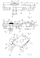
- 4 shows that the securing plate 13 is firmly connected to the cover rail 7 by means of bolts 17.
- the bolt 17 breaks through the drive rod 8 in the region of an elongated hole 19, so that the drive rod 8 can move freely from the fastening of the securing plate 13.
- This variant offers the advantage that to break out the window fitting 6 additional force must be used to destroy the cover rail together with the drive rod.
- the main advantage of this design is that the cover rail and drive rod are pressed against each other in the event of a break-open attempt and practically form an indestructible unit. This unit can practically only be broken open by impossible destruction of the bolts 17, 17a for the securing plate or mushroom button.
- the bolt 17 is mounted with its bolt head 18 in the locking plate 13 in a countersink 24, so that the top of the locking plate 13 is guided in the height direction to the fitting groove with play, which enables smoothness and smoothness.
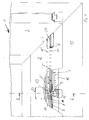
- FIG. 1 shows that the entry opening 20 for the securing plate 13 is created at the end of the frame spar 2 by a material recess.
- the inlet opening 20 is arranged in the area of the miter point 4, but without restricting the invention. For this purpose, it is only necessary to mill the miter area 4 where the fitting grooves of the frame spars 2, 3 meet. The entry opening 20 for the window fitting 6 according to the invention thus inevitably results at the end of the frame spar 2.
- FIG. 5 shows a securing plate 13, which is equipped on two of its opposite longitudinal edges 21 with teeth 22 pointing in the direction of the projection 14.
- the securing plate 13 claws behind the projection 14 when attempting to break open and thus achieves an additional counterforce which counteracts the breaking direction.
- the securing plate 13 can also engage behind the entire fitting groove 5.
- it can be supported, for example, on the inside of the frame behind the bottom 25 of the fitting groove 5.
- the bottom 25 then forms a technically equivalent means for the projections 14 of the fitting groove 5.
Abstract
Description
Die Erfindung betrifft einen Flügelrahmen mit durch Vorsprung hinterschnittener Beschlagnut zur Aufnahme von Deckschiene und Treibstange eines Fensterbeschlags, wobei die Treibstange mittels Pilzknopf ein zugeordnetes Schließstück am Blendrahmen hintergreift. Derartiger Flügelrahmen ist bekannt aus EP 628 691. Üblicherweise werden bei derartigen Flügelrahmen die Beschläge rundum geführt. Hierzu sitzen in den Eckbereichen geführte Umlenkvorrichtungen, z.B. elastische Federn, mit deren Hilfe die jeweils aneinander grenzenden Enden der dort ankommenden Beschläge gekoppelt werden.The invention relates to a casement frame with a recessed undercut fitting groove for receiving the cover rail and drive rod of a window fitting, the drive rod engaging behind an associated striker on the frame by means of a mushroom button. Such a sash frame is known from EP 628 691. Usually, with such sash frames, the fittings are guided all around. For this purpose, guided deflection devices are located in the corner areas, e.g. elastic springs, with the help of which the adjoining ends of the fittings arriving there are coupled.
Zur Erhöhung der Aufbruchsicherheit ist es aus der EP 0 628 691 bekannt, Pilzknöpfe derart vorzusehen, daß jeweils einer von mehreren Pilzknöpfen in Kipp- oder ein anderer der Pilzknöpfe in Verschlußstellung in das zugehörige Schließstück eingreift. Infolge der um die Ecke des Flügelrahmens herumgeführten Beschlagverbindung durch Koppelung konnte die Aufbruchsicherheit erheblich verbessert werden.To increase the security against break-out, it is known from EP 0 628 691 to provide mushroom buttons in such a way that one of several mushroom buttons in the tilting position or another one of the mushroom buttons engages in the associated closing piece in the locked position. As a result of the fitting connection being guided around the corner of the casement by coupling, the security against break-in has been considerably improved.
Es zeigt sich allerdings, daß eine Koppelung der Beschläge nicht immer erwünscht, möglich oder aber zu teuer ist.It turns out, however, that coupling the fittings is not always desirable, possible or too expensive.
Es ist daher Aufgabe der Erfindung, bei derartigem Flügelrahmen die Aufbruchsicherheit unter Vermeidung von Umlenkkoppelvorrichtungen in den Eckbereichen zu erhöhen.It is therefore an object of the invention to increase the security against break-open in such sash frames while avoiding deflection coupling devices in the corner areas.
Diese Aufgabe wird ausgehend von dem eingangs erwähnten Flügelrahmen dadurch gelöst, daß Deckschiene und Treibstange lediglich im Pilzknopfbereich mittels einer den Vorsprung der Beschlagnut hintergreifenden Sicherungsplatte gehalten werden, und daß die Beschlagnut eine außerhalb des Haltebereichs liegende Eintrittsöffnung für die Sicherungsplatte aufweist.This object is achieved on the basis of the casement mentioned at the outset in that the cover rail and drive rod are held only in the mushroom button area by means of a securing plate engaging behind the projection of the fitting groove, and in that the fitting groove has an entry opening for the securing plate lying outside the holding area.
Der Vorteil der Erfindung liegt darin, daß bei Aufbruchversuch die Position des Pilzknopfes am Flügel solange wie irgendmöglich gehalten wird.The advantage of the invention is that the position of the mushroom button on the wing is kept as long as possible when trying to break open.
Dieser Vorteil wird dadurch erzielt, daß die Sicherungsplatte eine Verankerung der Treibstange am Flügelrahmen bildet, welche mit der Verankerung des Pilzknopfes am zugeordneten Schließstück zusammenwirkt und daß auf diese Weise eine im wesentlichen starre Verbindung zwischen dem Blendrahmen und dem Flügelrahmen geschaffen wird.This advantage is achieved in that the securing plate forms an anchoring of the drive rod on the sash frame, which interacts with the anchoring of the mushroom button on the associated striker and in that way an essentially rigid connection is created between the frame and the sash frame.
Dabei hintergreift einerseits der Pilzknopf sein zugeordnetes Schließstück und die Sicherungsplatte den Vorsprung der Beschlagnut. Während so das Schließstück am Blendrahmen befestigt ist und die Sicherungsplatte am Flügelrahmen, wird auf diese Weise eine aufbruchgesicherte Verbindung zwischen Flügelrahmen und Blendrahmen geschaffen die nur unter äußerster Gewalteinwirkung zerstört werden kann. In diesem Falle müßte entweder die hintergreifende Zone des Pilzknopfes am Schließstück oder die hintergreifende Zone der Sicherungsplatte in der Beschlagnut gewaltsam aufgebrochen werden. Durch entsprechende Dimensionierung lassen sich allerdings die jeweils hintergreifenden Bereiche zwischen Pilzknopf/Schließstück und Sicherungsplatte/Beschlagnut so stabil ausbilden, daß einer vorzeitigen Zerstörung einer der beiden Eingriffszonen wirksam begegnet wird.On the one hand, the mushroom button engages behind its associated locking piece and the locking plate the projection of the fitting groove. While the striker is attached to the frame and the securing plate to the casement, a break-proof connection between casement and frame is created in this way, which can only be destroyed under extreme force. In this case, either the rear zone of the mushroom button on the striker or the rear zone of the locking plate in the hardware groove would have to be broken open. By appropriate dimensioning, however, the areas behind each mushroom button / striker and locking plate / hardware groove can be designed so stably that premature destruction of one of the two engagement zones is effectively countered.
Die Erfindung kann auf verschiedene Weise realisiert werden.The invention can be implemented in various ways.
Einerseits ist es denkbar, die Sicherungsplatte fest mit der Treibstange zu verbinden und mit Bewegungsspiel innerhalb der Beschlagnut zu lagern. Bei diesem Fall vollführt die Sicherungsplatte zwar auch die längsgerichtete Hin- und Herbewegung der Treibstange, sie wirkt dennoch im Falle eines Aufbruchversuches als Sicherung gegen Herausziehen des Beschlages aus der Beschlagnut. Bevorzugt ist sie unmittelbar am Pilzbolzen plaziert, so daß eine unverbiegbare zugfeste Verbindung zwischen Blendrahmen und Flügelrahmen entsteht.On the one hand, it is conceivable to firmly connect the securing plate to the drive rod and with play within the hardware groove. In this case, the securing plate also performs the longitudinal back and forth movement of the drive rod, but in the event of an attempt to break open, it nevertheless acts as a safeguard against the fitting being pulled out of the fitting groove. It is preferably placed directly on the mushroom bolt, so that an unbreakable, tensile connection between the frame and sash is created.
Andererseits kann die Sicherungsplatte auch fest mit der Deckschiene verbunden sein, vorzugsweise mittels starrem Bolzen. Zu diesem Zweck wird vorgeschlagen, daß der starre Bolzen die Treibstange im Bereich eines Langlochs durchbricht, so daß die Treibstange ungehindert frei beweglich ist.On the other hand, the securing plate can also be firmly connected to the cover rail, preferably by means of a rigid bolt. For this purpose, it is proposed that the rigid bolt break through the drive rod in the region of an elongated hole, so that the drive rod can move freely.
Ordnet man die Sicherungsplatte nach dieser Erfindung im Endbereich des jeweiligen Beschlags an, so ergibt sich der weitere Vorteil einer Eckensicherung des Beschlags am Flügelrahmen. Insbesondere können auf diese Weise, die stark einbruchgefährdeten Flügelrahmeneckbereiche zuverlässig gesichert werden.If one arranges the locking plate according to this invention in the end area of the respective fitting, there is the further advantage of securing the fitting on the sash frame at the corner. In particular, the sash frame corner areas which are at great risk of burglary can be reliably secured in this way.
Dabei hat sich gezeigt, daß die hintergreifende Sicherungsplatte durch die Anordnung im lokalen Bereich des Pilzknopfes oder unmittelbar daneben so stabil ausgeführt werden kann, daß der gesamte Beschlag lediglich im Endbereich gehalten werden muß und trotzdem aufbruchgesichert ist.It has been shown that the rear locking plate can be made so stable by the arrangement in the local area of the mushroom button or immediately next to it that the entire fitting only has to be held in the end area and is still secured against break-in.
Sieht man die Eintrittsöffnung für die Sicherungsplatte in die Beschlagnut endseitig des Rahmenholmes vor, so bietet dies den zusätzlichen Vorteil einer einfachen Montage des Beschlages. Der Vollständigkeit halber soll jedoch erwähnt sein, daß die Sicherungsplatte auch bei im wesentlichen rechteckigem Grundriß drehbar sein kann. Dann könnte die Sicherungsplatte in entsprechender Drehstellung mit der breiten Rechteckseite parallel zur Längsrichtung der Beschlagnut in die Beschlagnut eingeführt und dann soweit gedreht werden, daß danach die breite Rechteckseite senkrecht zur Längsrichtung des Beschlags steht und den Vorsprung der Beschlagnut hintergreift. In diesem Fall wird die Eintrittsöffnung von der Beschlagnut selbst gebildet.If one provides the entry opening for the securing plate in the fitting groove at the end of the frame spar, this offers the additional advantage of simple fitting of the fitting. For the sake of completeness, however, it should be mentioned that the securing plate can also be rotatable with an essentially rectangular plan. Then the locking plate could be inserted into the fitting groove in the appropriate rotational position with the wide rectangle side parallel to the longitudinal direction of the fitting groove and then turned so far that the wide rectangle side is then perpendicular to the lengthwise direction of the fitting and engages behind the projection of the fitting groove. In this case, the entry opening is formed by the hardware groove itself.
Hierzu wird weiterhin vorgeschlagen, daß eine Einführöffnung für die Sicherungsplatte im Bereich der Gehrung zweier aufeinander stoßender Rahmenholme angebracht wird (z.B. durch Ausfräsen). Hierdurch wird der Vorteil erreicht, daß stets eine genau definierte Position der Eintrittsöffnung vorliegt dies jedoch ohne Einfluß auf die angestrebte Festigkeit.For this purpose, it is further proposed that an insertion opening for the securing plate be provided in the area of the miter joint of two mutually abutting frame bars (e.g. by milling). This has the advantage that there is always a precisely defined position of the inlet opening, but this has no effect on the desired strength.
Allerdings kann die Montage dadurch vereinfacht werden, daß die Sicherungsplatte unverdrehbar starr mit Treibstange bzw. Deckschiene verbunden ist, so daß entsprechend ausgestalteter Fensterbeschlag einfach in die Eintrittsöffnung der Beschlagnut eingesteckt und längs verschoben wird.However, the assembly can be simplified in that the securing plate is non-rotatably rigidly connected to the drive rod or cover rail, so that the appropriately designed window fitting is simply inserted into the entry opening of the fitting groove and moved longitudinally.
Zusätzlich wird vorgeschlagen, die Längskanten der Sicherungsplatte, welche dem Vorsprung der Beschlagnut zugewandt sind, mit eingreifender Verzahnung auszustatten. Auf diese Weise wird sich im Falle eines Aufbruchsversuchs die Verzahnung in das Material der Wandungen der Aufnahmenut verkrallen und zusätzliche Sicherheit bieten.In addition, it is proposed to provide the longitudinal edges of the securing plate, which face the projection of the fitting groove, with engaging teeth. In this way, in the event of an attempt to break open, the toothing will claw into the material of the walls of the receiving groove and offer additional security.
Im folgenden wird die Erfindung anhand eines Ausführungsbeispiels näher erläutert. Es zeigen:
- Fig.1
- ein erstes Ausführungsbeispiel der Erfindung in frontaler Aufsicht,
- Fig.2
- ein Ausführungsbeispiel der Erfindung im Querschnitt gemäß Linie II-II nach Fig.1,
- Fig.3
- ein Ausführungsbeispiel mit Sicherungsplatte fest mit der Treibstange verbunden,
- Fig.4
- ein Ausführungsbeispiel mit Sicherungsplatte fest mit der Deckschiene verbunden,
- Fig.5
- Sicherungsplatte mit Verzahnung entlang ihrer Längskanten.
- Fig. 1
- a first embodiment of the invention in frontal supervision,
- Fig. 2
- an embodiment of the invention in cross section along line II-II of Figure 1,
- Fig. 3
- an embodiment with locking plate firmly connected to the drive rod,
- Fig. 4
- an embodiment with locking plate firmly connected to the cover rail,
- Fig. 5
- Locking plate with teeth along its long edges.
Sofern im folgenden nichts anderes gesagt ist, gilt die folgende Beschreibung stets für alle Figuren.Unless otherwise stated below, the following description always applies to all figures.
Die Figuren zeigen einen Flügelrahmen, wie er beispielsweise für Fenster oder Türen bekannt ist. Derartiger Flügelrahmen 1 besteht aus Rahmenholmen 2,3 die im Bereich von Gehrungsstellen 4 rechtwinklig zusammengesetzt sind. Üblicherweise sind derartige Rahmenholme aus Kunststoffprofilen gefertigt, dies jedoch ohne Einschränkung der Erfindung auf Kunststoffprofile. Es gibt derartige Flügelrahmen, wie an sich bekannt, auch aus Holz. Weiterhin sind derartige Holzrahmen bekannt geworden, bei denen die Beschlagnut 5 (siehe Fig.2) aus einem Kunststoffeinsatz besteht, der mit dem Material des Flügelrahmens fest verschraubt ist.The figures show a casement, as is known for example for windows or doors.
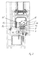
Wie man anhand von Fig.2 erkennt, bildet die Beschlagnut 5 eine längsverlaufende Materialausnehmung aus dem Flügelrahmen. Die Beschlagnut 5 weist dabei zwei sich gegenüberliegende Vorsprünge 14 auf, welche den engsten Querschnitt der Beschlagnut 5 definieren. In Richtung zur Glasseite des Flügelrahmens erweitert sich die Beschlagnut hinter den Vorsprüngen und bildet somit einen hinterschnittenen Bereich.As can be seen from FIG. 2, the
Wie an sich bekannt ist, dient die Beschlagnut 5 zur Aufnahme eines Fensterbeschlags 6. Derartiger Fensterbeschlag 6 besteht aus einer Deckschiene 7 und einer daran längsgeführten Treibstange 8. Üblicherweise wird die Deckschiene 7 mittels Schrauben durch entsprechende Langlöcher in der Treibstange 8 am Grunde der Beschlagnut 5 verschraubt und gegenüber dem Flügelrahmen gehalten. Wie man weiterhin erkennt, ist mit der Treibstange 8 fest verbunden sogenannter Pilzknopf 9. Es können auch paarweise Pilzknöpfe vorgesehen sein (s. EP 0 628 691), und zwar ein Pilzknopf für die Schließstellung und ein Pilzknopf für die Kippstellung des Flügelrahmens. Das zugeordnete Schließstück 10 weist hierzu jeweils entsprechende Längsausnehmungen auf, in welche die Pilzknöpfe mit ihrem Stielbereich einfahren, so daß die erweiterten Bereiche der Pilzknöpfe diese Einfahrschlitze hintergreifen und ein Aushebeln des Flügelrahmens so verhindert wird. Wie bereits erwähnt, kann die Deckschiene 7 mittels geeigneter Schrauben in der Beschlagnut 5 fixiert sein. Zusätzlich ist hier jedoch als Aufbruchsicherung vorgesehen, daß Deckschiene 7 und Treibstange 8 mittels einer den Vorsprung 14 der Beschlagnut 5 hintergreifenden Sicherungsplatte 13 am Flügelrahmen gehalten werden und daß die Beschlagnut 5 eine außerhalb des Haltebereichs 23 liegende Eintrittsöffnung 20 für die Sicherungsplatte 13 aufweist. Zusätzlich ist der Sonderfall gezeigt, daß die Sicherungsplatte 13 lediglich im Pilzknopfbereich 12 vorgesehen ist.As is known per se, the
Hieraus ergibt sich der Vorteil, daß der hintergreifende Bereich des Pilzknopfs 9 am Schließstück 10, und somit die Fixierung des Pilzknopfs gegenüber dem Blendrahmen 11 ein unmittelbar benachbartes und damit entsprechend stabiles Widerlager am Flügelrahmen 1 erhält. Während nämlich einerseits das Schließstück 10 fest mit dem Blendrahmen 11 verbunden ist, so daß der erweiterte Bereich des Pilzknopfes 9 aufbruchsicher mit dem Blendrahmen 11 in Verbindung gehalten wird, erfolgt die entsprechende Gegenlagerung des Fensterbeschlages 6 durch die Sicherungsplatte 13, welche die Vorsprünge 14 der Beschlagnut 5 aufbruchsicher hintergreift.This results in the advantage that the area behind the
Hierzu nimmt der erweiterte Bereich 15 der Beschlagnut 5 die Sicherungsplatte 13 auf, deren Breite 16 größer als die durch die Vorsprünge 14 verringerte Breite 15 der Beschlagnut 5 ist.For this purpose, the
Bei einem etwaigen Aufbruchversuch stemmt sich daher die Sicherungsplatte 13 fest gegen die Vorsprünge 14 und verhindert so ein Ausziehen des Fensterbeschlages 6 im aufbruchempfindlichen Fenstereckbereich.In the event of a possible attempt to break open, the securing
Wie Fig.3 und 4 erkennen lassen, kann einerseits die Sicherungsplatte 13 fest mit der Treibstange 8 verbunden sein. Sie macht dann die Längsbewegung der Treibstange 8 innerhalb des erweiterten Bereichs 15 der Beschlagnut 5 mit und ist zu diesem Zweck mit Bewegungsspiel in Längsrichtung innerhalb der Beschlagnut 5 gelagert. Hiervon abweichend zeigt Fig.4 daß die Sicherungsplatte 13 mittels Bolzen 17 fest mit der Deckschiene 7 verbunden ist. Der Bolzen 17 durchbricht die Treibstange 8 in dem Bereich eines Langlochs 19, so daß die Treibstange 8 ungehindert von der Befestigung der Sicherungsplatte 13 beweglich ist. Diese Variante bietet den Vorteil, daß zum Herausbrechen des Fensterbeschlags 6 zusätzliche Gewalt aufgewandt werden muß, um Deckschiene zusammen mit Treibstange zu zerstören. Der wesentliche Vorteil dieser Ausführung besteht darin, daß bei einem etwaigen Aufbruchversuch Deckschiene und Treibstange gegeneinander verpreßt werden und praktisch eine unzerstörbare Einheit bilden. Diese Einheit kann praktisch nur über unmögliche Zerstörung der Bolzen 17, 17a für Sicherungsplatte bzw. Pilzknopf aufgebrochen werden.As can be seen in FIGS. 3 and 4, on the one hand the securing
Wie weiterhin die Figuren erkennen lassen, ist der Bolzen 17 mit seinem Bolzenkopf 18 in der Sicherungsplatte 13 in einer Versenkung 24 gelagert, so daß die Oberseite der Sicherungsplatte 13 in Höhenrichtung zur Beschlagnut mit Spiel geführt ist, was Führigkeit und Leichtgängigkeit ermöglicht.As can also be seen from the figures, the bolt 17 is mounted with its
Zusätzlich zeigt Fig.1, daß die Eintrittsöffnung 20 für die Sicherungsplatte 13 endseitig des Rahmenholms 2 durch eine Materialausnehmung erstellt wird. Im vorliegenden Fall ist die Eintrittsöffnung 20 im Bereich der Gehrungsstelle 4 angeordnet, dies jedoch ohne Einschränkung der Erfindung. Zu diesem Zweck bedarf es lediglich einer Einfräsung des Gehrungsbereichs 4 dort wo die Beschlagnuten der Rahmenholme 2,3 aufeinander stoßen. Zwangsläufig ergibt sich somit endseitig des Rahmenholms 2 die Eintrittsöffnung 20 für den erfindungsgemäßen Fensterbeschlag 6.In addition, FIG. 1 shows that the entry opening 20 for the securing
Zusätzlich zeigt Fig.5 eine Sicherungsplatte 13, die an zwei ihrer gegenüberliegenden Längskanten 21 mit einer in Richtung zum Vorsprung 14 weisenden Verzahnung 22 ausgestattet ist. Mittels dieser Verzahnung krallt sich die Sicherungsplatte 13 beim Aufbruchversuch hinter den Vorsprung 14 und erzielt somit eine zusätzliche Gegenkraft, die der Aufbruchrichtung entgegen wirkt.In addition, FIG. 5 shows a securing
Prinzipiell kann die Sicherungsplatte 13 auch die gesamte Beschlagnut 5 hintergreifen. Hierzu kann sie z.B. auf der Rahmeninnenseite hinter dem Boden 25 der Beschlagnut 5 abgestützt sein. Der Boden 25 bildet dann ein technisch gleichwirkendes Mittel für die Vorsprünge 14 der Beschlagnut 5.In principle, the securing
- 11
- FlügelrahmenCasement
- 22nd
- RahmenholmFrame spar
- 33rd
- RahmenholmFrame spar
- 44th
- GehrungsstelleMiter point
- 55
- BeschlagnutHardware groove
- 66
- FensterbeschlagWindow fitting
- 77
- DeckschieneCover rail
- 88th
- TreibstangeConnecting rod
- 99
- PilzknopfMushroom button
- 1010th
- SchließstückStriker
- 1111
- BlendrahmenFrame
- 1212th
- Bereich des PilzknopfesArea of the mushroom button
- 1313
- SicherungsplatteLocking plate
- 1414
- Vorsprunghead Start
- 1515
- erweiterter Bereichextended area
- 1616
- Breite der SicherungsplatteWidth of the locking plate
- 1717th
- Bolzen für SicherungsplatteBolt for locking plate
- 17a17a
- Bolzen für PilzknopfBolt for mushroom button
- 1818th
- BolzenkopfBolt head
- 1919th
- Langloch in der TreibstangeElongated hole in the connecting rod
- 2020th
- EintrittsöffnungEntrance opening
- 2121
- LängskanteLong edge
- 2222
- VerzahnungGearing
- 2424th
- VersenkungSinking
- 2525th
- Boden der BeschlagnutBottom of the hardware groove
Claims (9)
- Casement frame (1) comprising mounting groove (5) recessed behind protrusions (14) for receiving cover strip (7) and motive rod (8) of a window fitting (6), wherein the motive rod (8) engages by means of mushroom-shaped stud (9) behind an associated latching member (10) on the blind frame (11), characterised in that cover strip (7) and motive rod (8) are held only in the mushroom-shaped stud region (12) by means of a retaining plate (13) which engages behind the protrusions (14) of the mounting groove (5), and that the mounting groove (5) comprises an entry aperture (20) for the retaining plate (13) located outside the retaining zone (23).
- Casement frame according to claim 1, characterised in that the retaining plate (13) is connected fixedly with the motive rod (8) and is mounted with play in the longitudinal direction within the mounting groove(5).
- Casement frame according to claim 1, characterised in that the retaining plate (13) is connected fixedly with the cover strip (7) by means of bolts (17) and that the bolts (17) pass through the motive rod (8) within the extent of an elongate hole (19).
- Casement frame according to one of claims 1 to 3, characterised in that the retaining plate (13) together with the mushroom-shaped stud (9) and latching member (10) are arranged in the end zone of the associated frame bar (2).
- Casement frame according to claim 4, characterised in that the window fitting (6) ends at the end side of the frame bar (2) and that the free end of the window fitting (6) is held there by the retaining plate (13).
- Casement frame according to one of claims 1 to 5, characterised in that the entry aperture (20) is produced by removing from the protrusions (14) of the mounting groove (5) material lying transversely to the longitudinal direction of the mounting groove (5).
- Casement frame according to claim 6, characterised in that the entry aperture (20) lies at the end of the frame bar (2) and preferably in the region of the mitre line (4).
- Casement frame according to one of claims 1 to 7, characterised in that the retaining plate (13) is connected rigidly non-rotatably with motive rod (8) or cover strip (7) and has a width (16) which corresponds to the internal width of the widened region (15) of the mounting groove (5).
- Casement frame according to one of claims 1 to 8, characterised in that the retaining plate (13), is provided at its lateral longitudinal edges (21) facing the protrusions (14) of the mounting groove (5) with serrations in engagement with the protrusions (14).
Applications Claiming Priority (2)
| Application Number | Priority Date | Filing Date | Title |
|---|---|---|---|
| DE29504824U | 1995-03-22 | ||
| DE29504824U DE29504824U1 (en) | 1995-03-22 | 1995-03-22 | Casement |
Publications (3)
| Publication Number | Publication Date |
|---|---|
| EP0733761A2 EP0733761A2 (en) | 1996-09-25 |
| EP0733761A3 EP0733761A3 (en) | 1996-12-04 |
| EP0733761B1 true EP0733761B1 (en) | 1997-08-13 |
Family
ID=8005679
Family Applications (1)
| Application Number | Title | Priority Date | Filing Date |
|---|---|---|---|
| EP96103709A Expired - Lifetime EP0733761B1 (en) | 1995-03-22 | 1996-03-09 | Wing frame |
Country Status (5)
| Country | Link |
|---|---|
| EP (1) | EP0733761B1 (en) |
| AT (1) | ATE156887T1 (en) |
| DE (2) | DE29504824U1 (en) |
| DK (1) | DK0733761T3 (en) |
| ES (1) | ES2105906T3 (en) |
Families Citing this family (4)
| Publication number | Priority date | Publication date | Assignee | Title |
|---|---|---|---|---|
| DE19739407C2 (en) * | 1997-09-09 | 2001-05-17 | Pax Gmbh | Window door |
| DE102008054614A1 (en) * | 2008-12-15 | 2010-06-17 | Aug. Winkhaus Gmbh & Co. Kg | Window with a wing pivotable against a frame |
| DE102013100133B4 (en) | 2013-01-08 | 2014-10-16 | Pax Ag | Frame hollow profile for a sash of a window or door |
| CN108639308A (en) * | 2018-05-11 | 2018-10-12 | 南京航天猎鹰飞行器技术有限公司 | A kind of wing mechanism for assembling-disassembling for Fixed Wing AirVehicle |
Family Cites Families (10)
| Publication number | Priority date | Publication date | Assignee | Title |
|---|---|---|---|---|
| DE7838570U1 (en) * | 1978-12-27 | 1979-04-12 | Siegenia-Frank Kg, 5900 Siegen | WINDOW, DOOR OR DGL. MADE FROM PLASTIC PROFILES |
| DE2931580A1 (en) * | 1979-08-03 | 1981-02-19 | Weidtmann Wilhelm Kg | Plastic or wooden window drive rod fittings fixture - involves sharp edges on turning holder cutting recesses into groove sides |
| AT367848B (en) * | 1980-02-18 | 1982-08-10 | Mayer & Co Riegel Beschlag | DEVICE FOR FASTENING WINDOW OR DOOR FITTING PARTS IN AN UNDERCUT PROFILE NUT |
| AT366755B (en) * | 1980-10-14 | 1982-05-10 | Lapp Finze Ag | CLAMPING DEVICE FOR FASTENING FITTING PARTS |
| DE3101393A1 (en) * | 1981-01-17 | 1982-09-02 | SCHÜCO Heinz Schürmann GmbH & Co, 4800 Bielefeld | "DOOR OR WINDOW WING EQUIPPED WITH A CUFF FITTING" |
| DE8323365U1 (en) * | 1983-08-13 | 1983-11-24 | Siegenia-Frank Kg, 5900 Siegen | DRIVE ROD FITTING FOR WINDOWS, DOORS OD. DGL. |
| DE3621419A1 (en) * | 1986-06-26 | 1988-01-07 | Erbsloeh Julius & August | Locking part for inhibiting break-ins on windows and French windows |
| DE3719011A1 (en) * | 1987-06-06 | 1988-12-22 | Bilstein August Gmbh Co Kg | LOCKING FITTING FOR WINDOWS, DOORS OD. DGL. |
| DE9217229U1 (en) * | 1992-12-17 | 1994-04-28 | Pax Schweikhard Gmbh | Push rod guide on window or door frame |
| DE9308472U1 (en) * | 1993-06-07 | 1993-09-02 | Pax Schweikhard Gmbh | Turn-tilt hardware for windows, doors or the like. |
-
1995
- 1995-03-22 DE DE29504824U patent/DE29504824U1/en not_active Expired - Lifetime
-
1996
- 1996-03-09 EP EP96103709A patent/EP0733761B1/en not_active Expired - Lifetime
- 1996-03-09 DE DE59600018T patent/DE59600018D1/en not_active Expired - Lifetime
- 1996-03-09 DK DK96103709.0T patent/DK0733761T3/en active
- 1996-03-09 ES ES96103709T patent/ES2105906T3/en not_active Expired - Lifetime
- 1996-03-09 AT AT96103709T patent/ATE156887T1/en active
Also Published As
| Publication number | Publication date |
|---|---|
| EP0733761A2 (en) | 1996-09-25 |
| ES2105906T3 (en) | 1997-10-16 |
| ATE156887T1 (en) | 1997-08-15 |
| EP0733761A3 (en) | 1996-12-04 |
| DE59600018D1 (en) | 1997-09-18 |
| DE29504824U1 (en) | 1996-08-08 |
| DK0733761T3 (en) | 1998-03-30 |
Similar Documents
| Publication | Publication Date | Title |
|---|---|---|
| EP2048297A2 (en) | Burglary resistant mullion and transom facade | |
| EP0492341B1 (en) | Locking device for two-winged window, or similar | |
| EP0433623B1 (en) | Locking device for a window, a door or similar | |
| EP0761920B1 (en) | Window/door with pivot and/or tilting fitting | |
| DE60038615T2 (en) | LOCK | |
| EP0733761B1 (en) | Wing frame | |
| EP0493689B1 (en) | Espagnolette for windows, doors or the like | |
| EP0786574A1 (en) | Fastener for locking the wing of a window or a door to the frame | |
| EP0247280B1 (en) | Hooking device between wings and frames of windows, doors or the like | |
| EP0748912A1 (en) | Window, door, or the like | |
| EP0844348A1 (en) | Hinge for doors or windows | |
| EP0128372B1 (en) | Device for fastening one wing of a pair of windows, doors or the like | |
| DE19745553A1 (en) | Fastening for frame-mounted window or door with handle | |
| EP0629767B1 (en) | Wooden door- or window frame | |
| EP0730074B1 (en) | Bolt device for mounting on the edge of the semi-fixed wing of double doors | |
| DE10229228A1 (en) | Door or window sash arrangement | |
| EP0500125B1 (en) | Fastening means for windows or doors | |
| DE19942563A1 (en) | Break-in security device for windows and doors has swivel yoke with recess corresponding to fixing knob set on casement window to interengage and block forced opening | |
| DE3342661A1 (en) | Espagnolette fitting | |
| EP0597484A1 (en) | Striker structure | |
| EP0158069B2 (en) | Closing and latching arrangement for doors and the like | |
| AT401404B (en) | FIRE PROTECTION DOOR WITH A DRIVE BAR CLOSURE | |
| EP0748911A1 (en) | Espagnolette for the wing of a door or a window | |
| EP0276379B1 (en) | Fastening device for armatures | |
| EP0756054A2 (en) | Window, door or the like |
Legal Events
| Date | Code | Title | Description |
|---|---|---|---|
| PUAI | Public reference made under article 153(3) epc to a published international application that has entered the european phase |
Free format text: ORIGINAL CODE: 0009012 |
|
| AK | Designated contracting states |
Kind code of ref document: A2 Designated state(s): AT BE CH DE DK ES FR GB IT LI LU NL PT SE |
|
| PUAL | Search report despatched |
Free format text: ORIGINAL CODE: 0009013 |
|
| AK | Designated contracting states |
Kind code of ref document: A3 Designated state(s): AT BE CH DE DK ES FR GB IT LI LU NL PT SE |
|
| 17P | Request for examination filed |
Effective date: 19961108 |
|
| GRAG | Despatch of communication of intention to grant |
Free format text: ORIGINAL CODE: EPIDOS AGRA |
|
| GRAH | Despatch of communication of intention to grant a patent |
Free format text: ORIGINAL CODE: EPIDOS IGRA |
|
| 17Q | First examination report despatched |
Effective date: 19970123 |
|
| GRAH | Despatch of communication of intention to grant a patent |
Free format text: ORIGINAL CODE: EPIDOS IGRA |
|
| GRAA | (expected) grant |
Free format text: ORIGINAL CODE: 0009210 |
|
| AK | Designated contracting states |
Kind code of ref document: B1 Designated state(s): AT BE CH DE DK ES FR GB IT LI LU NL PT SE |
|
| REF | Corresponds to: |
Ref document number: 156887 Country of ref document: AT Date of ref document: 19970815 Kind code of ref document: T |
|
| REG | Reference to a national code |
Ref country code: CH Ref legal event code: NV Representative=s name: E. BLUM & CO. PATENTANWAELTE Ref country code: CH Ref legal event code: EP |
|
| REF | Corresponds to: |
Ref document number: 59600018 Country of ref document: DE Date of ref document: 19970918 |
|
| ET | Fr: translation filed | ||
| GBT | Gb: translation of ep patent filed (gb section 77(6)(a)/1977) |
Effective date: 19970919 |
|
| REG | Reference to a national code |
Ref country code: ES Ref legal event code: FG2A Ref document number: 2105906 Country of ref document: ES Kind code of ref document: T3 |
|
| ITF | It: translation for a ep patent filed |
Owner name: STUDIO TORTA S.R.L. |
|
| REG | Reference to a national code |
Ref country code: PT Ref legal event code: SC4A Free format text: AVAILABILITY OF NATIONAL TRANSLATION Effective date: 19970918 |
|
| REG | Reference to a national code |
Ref country code: DK Ref legal event code: T3 |
|
| PLBE | No opposition filed within time limit |
Free format text: ORIGINAL CODE: 0009261 |
|
| STAA | Information on the status of an ep patent application or granted ep patent |
Free format text: STATUS: NO OPPOSITION FILED WITHIN TIME LIMIT |
|
| 26N | No opposition filed | ||
| PGFP | Annual fee paid to national office [announced via postgrant information from national office to epo] |
Ref country code: SE Payment date: 20000228 Year of fee payment: 5 Ref country code: PT Payment date: 20000228 Year of fee payment: 5 |
|
| PGFP | Annual fee paid to national office [announced via postgrant information from national office to epo] |
Ref country code: DK Payment date: 20000303 Year of fee payment: 5 |
|
| PGFP | Annual fee paid to national office [announced via postgrant information from national office to epo] |
Ref country code: GB Payment date: 20000308 Year of fee payment: 5 |
|
| PGFP | Annual fee paid to national office [announced via postgrant information from national office to epo] |
Ref country code: AT Payment date: 20000314 Year of fee payment: 5 |
|
| PGFP | Annual fee paid to national office [announced via postgrant information from national office to epo] |
Ref country code: ES Payment date: 20000315 Year of fee payment: 5 |
|
| PG25 | Lapsed in a contracting state [announced via postgrant information from national office to epo] |
Ref country code: GB Free format text: LAPSE BECAUSE OF NON-PAYMENT OF DUE FEES Effective date: 20010309 Ref country code: DK Free format text: LAPSE BECAUSE OF NON-PAYMENT OF DUE FEES Effective date: 20010309 Ref country code: AT Free format text: LAPSE BECAUSE OF NON-PAYMENT OF DUE FEES Effective date: 20010309 |
|
| PG25 | Lapsed in a contracting state [announced via postgrant information from national office to epo] |
Ref country code: SE Free format text: LAPSE BECAUSE OF NON-PAYMENT OF DUE FEES Effective date: 20010310 Ref country code: ES Free format text: LAPSE BECAUSE OF NON-PAYMENT OF DUE FEES Effective date: 20010310 |
|
| PG25 | Lapsed in a contracting state [announced via postgrant information from national office to epo] |
Ref country code: PT Free format text: LAPSE BECAUSE OF NON-PAYMENT OF DUE FEES Effective date: 20010930 |
|
| GBPC | Gb: european patent ceased through non-payment of renewal fee |
Effective date: 20010309 |
|
| EUG | Se: european patent has lapsed |
Ref document number: 96103709.0 |
|
| REG | Reference to a national code |
Ref country code: DK Ref legal event code: EBP |
|
| REG | Reference to a national code |
Ref country code: PT Ref legal event code: MM4A Free format text: LAPSE DUE TO NON-PAYMENT OF FEES Effective date: 20010930 |
|
| REG | Reference to a national code |
Ref country code: ES Ref legal event code: FD2A Effective date: 20030203 |
|
| PGFP | Annual fee paid to national office [announced via postgrant information from national office to epo] |
Ref country code: NL Payment date: 20030328 Year of fee payment: 8 |
|
| PGFP | Annual fee paid to national office [announced via postgrant information from national office to epo] |
Ref country code: BE Payment date: 20040315 Year of fee payment: 9 |
|
| PGFP | Annual fee paid to national office [announced via postgrant information from national office to epo] |
Ref country code: LU Payment date: 20040331 Year of fee payment: 9 |
|
| PG25 | Lapsed in a contracting state [announced via postgrant information from national office to epo] |
Ref country code: LU Free format text: LAPSE BECAUSE OF NON-PAYMENT OF DUE FEES Effective date: 20050309 Ref country code: IT Free format text: LAPSE BECAUSE OF NON-PAYMENT OF DUE FEES;WARNING: LAPSES OF ITALIAN PATENTS WITH EFFECTIVE DATE BEFORE 2007 MAY HAVE OCCURRED AT ANY TIME BEFORE 2007. THE CORRECT EFFECTIVE DATE MAY BE DIFFERENT FROM THE ONE RECORDED. Effective date: 20050309 |
|
| PG25 | Lapsed in a contracting state [announced via postgrant information from national office to epo] |
Ref country code: BE Free format text: LAPSE BECAUSE OF NON-PAYMENT OF DUE FEES Effective date: 20050331 |
|
| BERE | Be: lapsed |
Owner name: *PAX G.M.B.H. Effective date: 20050331 |
|
| PG25 | Lapsed in a contracting state [announced via postgrant information from national office to epo] |
Ref country code: NL Free format text: LAPSE BECAUSE OF NON-PAYMENT OF DUE FEES Effective date: 20051001 |
|
| NLV4 | Nl: lapsed or anulled due to non-payment of the annual fee |
Effective date: 20051001 |
|
| REG | Reference to a national code |
Ref country code: CH Ref legal event code: PFA Owner name: PAX GMBH Free format text: PAX GMBH#GEWERBEGEBIET RUESTERBAUM, VORDERER BOEHL 39#D-55218 INGELHEIM (DE) -TRANSFER TO- PAX GMBH#GEWERBEGEBIET RUESTERBAUM, VORDERER BOEHL 39#D-55218 INGELHEIM (DE) |
|
| BERE | Be: lapsed |
Owner name: *PAX G.M.B.H. Effective date: 20050331 |
|
| REG | Reference to a national code |
Ref country code: DE Ref legal event code: R082 Ref document number: 59600018 Country of ref document: DE Representative=s name: MUELLER, JOCHEN, DIPL.-ING., DE Ref country code: DE Ref legal event code: R082 Ref document number: 59600018 Country of ref document: DE Representative=s name: JOCHEN MUELLER, DE |
|
| PGFP | Annual fee paid to national office [announced via postgrant information from national office to epo] |
Ref country code: CH Payment date: 20130522 Year of fee payment: 18 |
|
| PGFP | Annual fee paid to national office [announced via postgrant information from national office to epo] |
Ref country code: DE Payment date: 20140325 Year of fee payment: 19 |
|
| PGFP | Annual fee paid to national office [announced via postgrant information from national office to epo] |
Ref country code: FR Payment date: 20140319 Year of fee payment: 19 |
|
| REG | Reference to a national code |
Ref country code: CH Ref legal event code: PL |
|
| PG25 | Lapsed in a contracting state [announced via postgrant information from national office to epo] |
Ref country code: LI Free format text: LAPSE BECAUSE OF NON-PAYMENT OF DUE FEES Effective date: 20140331 Ref country code: CH Free format text: LAPSE BECAUSE OF NON-PAYMENT OF DUE FEES Effective date: 20140331 |
|
| REG | Reference to a national code |
Ref country code: DE Ref legal event code: R119 Ref document number: 59600018 Country of ref document: DE |
|
| REG | Reference to a national code |
Ref country code: FR Ref legal event code: ST Effective date: 20151130 |
|
| PG25 | Lapsed in a contracting state [announced via postgrant information from national office to epo] |
Ref country code: DE Free format text: LAPSE BECAUSE OF NON-PAYMENT OF DUE FEES Effective date: 20151001 |
|
| PG25 | Lapsed in a contracting state [announced via postgrant information from national office to epo] |
Ref country code: FR Free format text: LAPSE BECAUSE OF NON-PAYMENT OF DUE FEES Effective date: 20150331 |