EP1110033B1 - Bruleur destine a des combustibles liquides - Google Patents
Bruleur destine a des combustibles liquides Download PDFInfo
- Publication number
- EP1110033B1 EP1110033B1 EP99936224A EP99936224A EP1110033B1 EP 1110033 B1 EP1110033 B1 EP 1110033B1 EP 99936224 A EP99936224 A EP 99936224A EP 99936224 A EP99936224 A EP 99936224A EP 1110033 B1 EP1110033 B1 EP 1110033B1
- Authority
- EP
- European Patent Office
- Prior art keywords
- burner
- flame retention
- flame
- vaporizing chamber
- temperature
- Prior art date
- Legal status (The legal status is an assumption and is not a legal conclusion. Google has not performed a legal analysis and makes no representation as to the accuracy of the status listed.)
- Expired - Lifetime
Links
Images


Classifications
-
- F—MECHANICAL ENGINEERING; LIGHTING; HEATING; WEAPONS; BLASTING
- F23—COMBUSTION APPARATUS; COMBUSTION PROCESSES
- F23D—BURNERS
- F23D11/00—Burners using a direct spraying action of liquid droplets or vaporised liquid into the combustion space
- F23D11/36—Details, e.g. burner cooling means, noise reduction means
- F23D11/40—Mixing tubes or chambers; Burner heads
- F23D11/406—Flame stabilising means, e.g. flame holders
-
- F—MECHANICAL ENGINEERING; LIGHTING; HEATING; WEAPONS; BLASTING
- F23—COMBUSTION APPARATUS; COMBUSTION PROCESSES
- F23D—BURNERS
- F23D11/00—Burners using a direct spraying action of liquid droplets or vaporised liquid into the combustion space
- F23D11/36—Details, e.g. burner cooling means, noise reduction means
- F23D11/44—Preheating devices; Vaporising devices
- F23D11/441—Vaporising devices incorporated with burners
- F23D11/443—Vaporising devices incorporated with burners heated by the main burner flame
- F23D11/445—Vaporising devices incorporated with burners heated by the main burner flame the flame and the vaporiser not coming into direct contact
-
- F—MECHANICAL ENGINEERING; LIGHTING; HEATING; WEAPONS; BLASTING
- F23—COMBUSTION APPARATUS; COMBUSTION PROCESSES
- F23D—BURNERS
- F23D11/00—Burners using a direct spraying action of liquid droplets or vaporised liquid into the combustion space
- F23D11/36—Details, e.g. burner cooling means, noise reduction means
- F23D11/44—Preheating devices; Vaporising devices
- F23D11/441—Vaporising devices incorporated with burners
- F23D11/448—Vaporising devices incorporated with burners heated by electrical means
Definitions
- the invention relates to a burner in the preamble of claim 1 mentioned type.
- Such burners are advantageous in heating systems of residential and non-residential buildings used.
- the heat generated by the burner when burning the fuel heats
- gaseous Fuels like natural gas.
- the latter are characterized in particular by the fact that their Heat generation over a wide power range is controllable, which in the professional world with Modulability is called.
- gas burners have favorable values in terms of Pollutant emission.
- Burners for liquid fuels are widely used. While at firings of Industrial plants burners used for heavy oil, dominate in heating systems in residential and non-residential buildings burners for light fuel oil, in particular such the Type "extra light fuel oil”. Sputtering burners, in which the fuel oil produced by an oil pump is atomized by means of a nozzle and burned directly becomes. Such burners are only available from higher powers, e.g. greater than 100 kW, modulated. Because of structural measures such as better insulation of buildings is in the last two decades of specific heating demand declined. Atomizing burners are only suitable for heating systems with a rated output of 15 kW and more.
- Evaporator burner created. With them, the fuel is by heat evaporated, then mixed with air and burned. Such burners were first mainly used for burning kerosene or kerosene, because these Fuels have a relatively low evaporation temperature. When kerosene or kerosene, the relevant industry has so-called Evaporator burner created. With them, the fuel is by heat evaporated, then mixed with air and burned. Such burners were first mainly used for burning kerosene or kerosene, because these Fuels have a relatively low evaporation temperature. When kerosene or
- Burner start in the evaporation chamber by means of an electric heater on the To heat evaporation temperature, but later, when the heater together with Burner has been heated so far that the evaporation of kerosene or Petroleum is maintained by the heat of the heater, the to turn off the electric heater.
- Electric heater For fuel oil is extra light, however, because of at this fuel much higher evaporation temperature of the continuous operation of the electric heater needed.
- a burner referred to in the preamble of claim 1 is known from FR-A 1-2 733 579 known. This burner is intended for the combustion of kerosene, it being It seems questionable whether he could also be particularly suitable for heating oil. He contains the already mentioned electric heater, which is then turned on when a Temperature sensor indicates the need for preheating. It is not clear whether he switches off the preheating after the burner start again. Since the Temperature sensor is also not shown, is also not recognizable where and how he should be arranged.
- a burner for the combustion of He ⁇ zöl extra slightly more suitable is known from DE-A1-25 34 066 known. It contains the already mentioned electric heater. It does not serve only heating of fuel, but also warming of for combustion required air that will connect, that the already evaporated fuel again condensed. Insufficient heating would cause the fuel to fail clean burned, but partially coked, resulting in a short time to a malfunction of the burner leads.
- the invention is based on the object, one for the combustion of Schuol extra light to provide suitable burner in which the evaporator chamber by means of the mentioned electric heater only during the start-up phase with a cold burner heated must be during the subsequent operation of the burner, the supply of Foreign energy is unnecessary for heating the fuel.
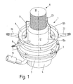
- 1 means a burner having a blower 3 held by a flange 3 has, through which a connection hose 10 fresh air can be supplied.
- a motor 4 is arranged, which drives the fan 3.
- a burner pot 5 is placed, on its upper side with a connecting flange. 6 is provided, with the burner 1 from below on a boiler, not shown can be mounted.
- a fuel connection 7 is provided at the top of the blower 3.
- the Burner 1 the fuel oil supplied. From fuel port 7, the fuel oil passes through a This view not visible fuel line in a in this view also not visible evaporator chamber.
- a temperature sensor In the wall of the burner pot 5 is a temperature sensor.
- the wall becomes of the burner pot 5 of a first holder 26 pierced, the recording of a Ignition device, for example, an ignition electrode 9 or a Glühzünders serves.
- a Ignition device for example, an ignition electrode 9 or a Glühzünders serves.
- This igniter of the fuel-air mixture serving ignition electrode 9 is so stirred, that you one end in the area of the burner 1, in which the flame should arise.
- This range is given by a cylindrical flame holder 11, the protruding from a Umlenkkragen 12 and at its top with a lid 35th is closed.
- the Umlenkkragen 12 consists of a cylindrical portion 12 a and a adjoining oblique approach 12b.
- the flame holder 11 is on in this Representation not visible evaporator chamber attached. It is advantageous heat resistant steel or ceramic.
- the Umlenkkragen 12 is advantageous heat-resistant steel sheet, possibly also made of cast steel.
- FIG. 1 further shows an electrode 23, which in the wall of the burner pot 6 by means of a further bracket 22 is attached.
- the free end of this electrode 23 lies in one certain distance parallel to the surface of the flame holder 11.
- the electrode 23 belongs to an ionization, not shown, with the presence of a Flame is monitorable. This monitoring is carried out by a burner. 1 assigned, but not shown here burner control unit, as in the prior Technology Start and operation of the burner 1 controls and monitors.
- FIG. 2 shows a vertical section through the burner 1 shown in FIG more details are recognizable. Shown here is a first embodiment of the Burner 1.
- the motor 4 can be seen, the blower. 3 (Fig. 1) drives.
- the blower. 3 (Fig. 1) drives.
- only one motor 4 and blower 3 from the fan 3 common drive shaft 14 can be seen, on which a first rotor 15 and a second Rotor 16 are attached.
- the flame holder 11 with its lid 35 can be seen, wherein It can also be seen that the flame holder 11 on a in connection with FIG. 1 already mentioned evaporator chamber 17 is seated. Down is the Evaporator chamber 17 is closed by a bottom 19. The one of the Evaporator chamber 17 and its bottom 19 enclosed space forms a mixed and Evaporator zone 18. In the wall of the evaporator chamber 17 is an electrical Heating device 20 integrated.
- the flame holder 11 is surrounded by a firebox 21. In this room burns the Flame.
- the cylindrical shell of the flame holder 11 consists of at least one, advantageous but from two nested perforated plates, namely an outer Perforated plate 24 and an inner perforated plate 25.
- the in these perforated plates 24, 25 existing openings may be circular or oblong, so for example as well Slits be formed. In addition, other forms are possible.
- the openings of the two Perforated sheets 24, 25 may be different sizes. For example, the holes in the outer perforated plate 24 may be smaller than those in the inner perforated plate 25. Also the hole grid can have different dimensions.
- the size of the Vents varies by, for example, the openings in the lower, the Evaporation chamber 17 facing area are larger and the size of the openings towards the top, ie in the direction of the lid 35, decreases.
- the from the two Perforated plates 24, 25 formed cylinders can be pushed directly into each other, but there can advantageously be a more or less large gap between them be.
- the outer perforated plate 24 burn small partial flames, the together form a very stable flame carpet.
- Through the inner perforated plate 25 is achieved that the mixing of fuel and air is further improved.
- the inner perforated plate 25 a much lower temperature
- the outer perforated plate 24 by this measure is a repelling the Flame in the interior of the flame holder 11 largely excluded.
- the specified designs of the flame holder 11 also have the advantage that the flame burns very evenly, which also manifests itself in a low noise level.
- Umlenkkragen 12 extends with his cylindrical part 12a is not up to the bottom of the burner pot 5 (Fig. 1), but is below held in the burner pot 5 by means of, for example, three unillustrated legs.
- Fig. 1 The surrounding part of the flame holder 11 Umlenkkragen 12 extends with his cylindrical part 12a is not up to the bottom of the burner pot 5 (Fig. 1), but is below held in the burner pot 5 by means of, for example, three unillustrated legs.
- an annular gap 34 remains open in between.
- the burner control unit first the electric heater 20 turns on.
- the evaporator chamber 17 by means External energy heated.
- the fan 3 rotate with the Drive shaft 14 connected parts such as rotors 15, 16, mixing 28, baffle 29 and Atomizer cup 30.
- a feed pump which is equipped with the Combustion of incoming fuel oil from a tank in the burner 1 promotes, in operation set.
- the fresh air flows on the one hand on the outside Atomizer cup 30 along, on the other hand, through openings in the bottom of the Atomizer cup 30 through the interior of the atomizer cup 30 against the baffle 29th Both partial flows then flow around the mixing wheel 28 and the guide plate 29 around. In the Fig. 2 this is indicated by arrows.
- the speed of the Feed pump smaller or larger, the speeds of feed pump and blower 3rd are coordinated so that the amounts of fuel and air so on each other are tuned that the most complete combustion takes place.
- the Feed pump for example, no gear pump, but a piston pump, occurs to the Set the speed another variable characterizing the flow volume. It is essential that the required volumes of air and fuel in a correct ratio stand.
- the evaporator chamber 17 preheated, so that here now by the atomization already finely distributed fuel oil evaporated and at the same time mixed intensively with the fresh air flowing through.
- the combustible mixture of fuel oil vapor and air due to tuned speeds of feed pump and blower 3 is approximately stoichiometrically composed, now occurs in the interior of the flame holder 11, which in Fig. 2 also by arrows is marked. Then this mixture enters through the holes in the Perforated sheets 24, 25 through. From the burner control unit is at the appropriate time the ignition is switched on.
- the ignition electrode 9 is under tension and ignites the combustible mixture. Now burns on the shell compartment of the flame holder 11 a coherent flame and the hot exhaust fumes flow into the firebox 21.
- the Combustion chamber 21 is surrounded by the heat exchanger of the boiler, which in Figs. 1 and 2 not shown.
- FIGS. 1 and 2 these means are in the form of Umlenkkragens 12th shown. Other, equally effective embodiments are within the scope of the invention possible.
- Those hot exhaust gases, in the space surrounded by Umlenkkragen 12 space Flame holder 11 arise are directed by the Umlenkkragen 12 down, which in Fig. 2 is again indicated by arrows.
- the hot exhaust gases thus act from the outside to the evaporator chamber 17 and heat it up.
- the temperature sensor 8 is mounted on the burner pot 5 (FIG.
- Temperature sensor 8 is determined whether in the burner pot 5 and thus at the Evaporator chamber 17, the required for the evaporation of the fuel oil temperature at Extra light oil at least 350 degrees Celsius, is reached.
- the temperature sensor 8 thus determines the actual value of the temperature and outputs this measured value to the burner control unit which compares the actual value of the temperature with a target value and the when the actual value is higher than the target value, the electric heater 20 off.
- the temperature sensor 8, together with the burner control unit and the electric heater 20 also act so that the temperature in the Evaporator chamber 17 not only when reaching a certain temperature is switched off, but that the temperature in the evaporator chamber 17 really regulated is, e.g. according to a PID algorithm. This can be beneficial if the burner is in an extremely cold climate zone is used.
- the electrical heating device 20 it would also be possible for the electrical heating device 20 to have a specific, for Example to disable adjustable time after the appearance of the flame.
- the solution with however, the shutdown controlled by the temperature sensor 8 is Operational safety and efficiency advantageous. This adjusts the shutdown of electric heater 20 also automatically to the effective heat output of Burner 1, if this modulating, so with smaller or larger power, is operated.
- the device according to the invention it is ensured that in the Evaporator chamber 17 necessary for complete evaporation of the fuel oil Temperature prevails, so that it can be ruled out that coked the fuel oil and the Burner 1 dirty and prone to failure.
- the large lateral surface of the flame holder 11 also has the advantage that a large-area flame is produced whose temperature is smaller than in burners according to the prior art. This has an advantageous effect because less nitrogen oxides NO x are formed in the burner 1 according to the invention.
- a further advantage is that in such a burner 1 only small pressure differences, both on the fuel, as well as on the air side, are necessary, which manifests itself positively in a low noise level.
- the burner 1 according to the invention can therefore also be used without problems in multi-storey heating systems, where otherwise gas burners are usually preferred because of the low noise level inherent in this burner type.
- FIG. 3 shows a vertical section of a second embodiment. Same Parts are provided with the same reference numbers. It is advantageous in this Embodiment centrally in the interior of the flame holder 11 an insert 36th arranged, which consists of heat-resistant steel.
- the insert 36 is rotationally symmetrical and consists of a frustoconical upper part 37 and a adjoining conical lower part 38.
- 36 is the from Fuel-air mixture in the interior of the flame holder 11 filled volume reduced and the shape of the insert 36 is achieved that effectively effective cross section in the flame holder 11 decreases from bottom to top.
- FIG. 3 also shows another embodiment inside the evaporator chamber, which is provided here in contrast to FIG. 2 with the reference numeral 39.
- These Embodiment differs from that of FIG. 2 also in that baffle 29, Mixing wheel 28 and perforated disc 27 are missing. This results in a modified preparation of the fuel-air mixture.
- the fuel oil Under the action of the centrifugal force against the inner wall of the evaporator chamber 39 hurled, whereupon it evaporates there.
- the evaporated fuel oil is replaced by a first Partial flow of the blower 3 (Fig. 1) conveyed air through a gap 40 on the outside Atomizer cup 30 is passed, taken, with the partial flow of air and mix the steam of the heating oil.
- this partial flow of air in the Evaporator chamber 39 is heated.
- a second partial flow flows from the fan 3 (FIG. 1) through the interior of the below also here open atomizer cup 30 and remains unheated and thus does not cool the evaporator chamber 39.
- Above the atomizer cup 30 unite the two streams, so that only here a complete mixing of Fuel and air takes place.
- the air supply zone 42 is formed by the blower 3, comprises the evaporator zone 43 the atomizer cup 30 and the interior of the evaporator chamber 39.
- the actual Mixing zone 41 is formed here from the interior of the flame holder 11, wherein the Mixing of fuel and air is also improved by that in this Embodiment between the outer perforated plate 24 and the inner perforated plate 25th there is a clear gap.
- connection hose 10 In contrast to the example of Fig. 1, the fan 3, the air is not a Connection hose 10 is supplied, but the air can via an opening 44 in the housing of the blower 3 from the immediate vicinity of the burner 1 to flow. But it can also, a connection hose 10 (Fig. 1) may be provided.
- Fig. 3 is also shown in more detail how the burner 1 to a boiler 50th is fastened.
- the burner pot provided in FIG. 1 with the reference numeral 5, is here with the reference numeral 45 denotes.
- the burner pot 45 At its upper end, the burner pot 45 a Flange 46, the outer end 47 is bent downwards.
- a clamping ring 48 encloses the outer end 47 of the burner pot 45 and at the same time a lug 49 on Boiler 50.
- FIG. 3 is also shown by way of example, how the attachment of the burner 1 to the boiler 50 clearly positioned executed is. From the outer end 47 of the flange 46, a tab 51 is bent upwards, in a recess 52 in the projection 49 of the boiler 50 engages.
- Fig. 4 alternative embodiments are shown with which according to the invention an influence of that partial flow of hot exhaust gases is possible with which, as in the Explanation of Fig. 2 mentioned, the evaporator chamber 17 is heated from the outside. It has proved to be advantageous when means are available to this partial flow to affect the temperature of the evaporator chamber 17 under all load conditions to keep it constant.
- the first embodiment relates to the execution of the oblique approach 12b of Umlenkkragens 12. This consists advantageous Thermobimetall so that he changed its shape with a change in temperature by bulges. A achievable by such a change in temperature second position is in 4 with the reference numeral 12b 'shown. This change in shape changes at Temperature change the width of the annular gap 34, which is due to the size of the partial flow of the hot exhaust gases has influence.
- a second variant for influencing the partial flow of hot exhaust gases exists in that a portion 56 of the cylindrical portion 12a of Umlenkkragens 12 of Thermobimetal exists.
- this section 56 cambers due to the action of heat, arises in the cylindrical portion 12a a discharge opening 57, through which a part of the partial flow the hot exhaust gases can escape again, so that it has no thermal influence on the Can exert evaporation chamber 17. This is the case of very hot exhaust gases Evaporator chamber 17 less heated.
- this section 56 is also slotted.
- a third variant is that around the outer surface of the Evaporator chamber 17, a collar 58 is placed, which also consists of bimetallic strip. Also this collar 58 warps under heat. This will change the size of the free cross section between the evaporator chamber 17 and the cylindrical part 12 a of the Umlenkkragens 12 changed, which is directly on the partial flow of the hot exhaust gases affects, which affects the evaporator chamber 17 thermally.
- the insert 36 can also be used in the first embodiment Fig. 2 are applied.
- a flame holder 11 concentrically enclosing, not shown in the figures spiral, which has the task to dissipate heat from the flame. With this measure it is achieved that the flame temperature is lower, which manifests itself advantageously in a lower content of nitrogen oxides NO x .
- the variants of the burner 1 described above are in the ratio of 1: 3 modulated, so that the power of the burner 1, for example, between 5 and 15 kW is controllable.
Landscapes
- Engineering & Computer Science (AREA)
- Chemical & Material Sciences (AREA)
- Combustion & Propulsion (AREA)
- Mechanical Engineering (AREA)
- General Engineering & Computer Science (AREA)
- Feeding And Controlling Fuel (AREA)
- Evaporation-Type Combustion Burners (AREA)
- Spray-Type Burners (AREA)
- Control Of Combustion (AREA)
- Regulation And Control Of Combustion (AREA)
Claims (11)
- Brûleur (1) pour combustible liquide, en particulier du fuel extra-léger, avec un élément de commande du brûleur -une soufflerie (3) entraínée par un moteur (4) étant montée sur le brûleur (1) qui présente un pot de brûleur (5, 45) avec une chambre d'évaporation (17, 39) et un organe de pulvérisation (30, 28) placé dans la chambre d'évaporation (17, 39), ainsi qu'un dispositif de chauffage électrique (20) - un accrocheur de flamme (11) cylindrique se trouvant sur la chambre d'évaporation (17, 39), sur le pourtour perforé duquel se forme la flamme lors du fonctionnement du brûleur et sur lequel est disposé un capteur thermique (8) dont le signal est émis à l'élément de commande du brûleur qui décide s'il est nécessaire de mettre en marche le dispositif de chauffage électrique (20),
caractérisé en ce que,des moyens (12) sont présents, avec lesquels une partie du courant des effluents gazeux brûlants est déviée de telle manière qu'elle chauffe de l'extérieur la chambre d'évaporation (17, 39) de telle manière qu'une température d'au moins 350 degrés Celsius est atteinte dans la chambre d'évaporation (17, 39),le capteur thermique (8) est monté dans la paroi du pot de brûleur (5, 45), et en ce quel'élément de commande du brûleur arrête, au démarrage du brûleur (1), le dispositif de chauffage électrique (20) allumé dès que la valeur réelle de la température mesurée par le capteur thermique (8) sur le pot de brûleur (5, 45) dépasse une valeur de consigne réglée dans l'élément de commande du brûleur. - Brûleur selon la revendication 1, caractérisé en ce que les moyens sont formés pour dévier une partie du courant des effluents gazeux brûlants par un élément déflecteur (12) qui enveloppe de manière concentrique une partie de l'accrocheur de flamme (11).
- Brûleur selon la revendication 2, caractérisé en ce que le courant d'air transporté par la soufflerie (3) est réparti avant la chambre d'évaporation (17, 39) en un premier et un second courant partiel ; le premier courant partiel étant mélangé avec le combustible évaporé dans la chambre d'évaporation (17,39) tandis que le second courant partiel est amené à travers un récipient de pulvérisateur (30) appartenant à l'organe de pulvérisation (30, 28) de telle manière que la chambre d'évaporation (17, 39) ne refroidit pas.
- Brûleur selon l'une des revendications 1 à 3, caractérisé en ce que le pourtour de l'accrocheur de flamme (11) est formé par une tôle perforée (24, 25) tandis que l'accrocheur de flamme (11) est fermé sur sa face supérieure par un couvercle (35).
- Brûleur selon la revendication 4, caractérisé en ce qu'une seconde tôle perforée (25) est disposée à l'intérieur d'une première tôle perforée (24) formant le pourtour de l'accrocheur de flamme (11).
- Brûleur selon la revendication 5, caractérisé en ce que les trous de la tôle perforée extérieure 24 sont plus petits que ceux de la tôle perforée intérieure 25.
- Brûleur selon les revendications 4 à 6, caractérisé en ce que l'accrocheur de flamme (11) est composé d'une tôle d'acier réfractaire ou de céramique.
- Brûleur selon l'une des revendications 2 à 7, caractérisé en ce qu'un vide annulaire (34) se trouve entre le pourtour de l'accrocheur de flamme (11) et l'élément déflecteur (12).
- Brûleur selon la revendication 8, caractérisé en ce que des moyens (12b, 55) sont présents afin de modifier la grandeur du vide annulaire (34) et/ou des moyens (56, 57, 58) afin d'influencer la partie déviée du courant des effluents gazeux brûlants selon la température des effluents gazeux.
- Brûleur selon l'une des revendications 2 à 9, caractérisé en ce qu'au milieu à l'intérieur de l'accrocheur de flamme (11) est disposé un insert (36) symétrique en révolution par lequel la section transversale réellement efficace à l'intérieur de l'accrocheur de flamme (11) diminue de bas en haut.
- Brûleur selon la revendication 10, caractérisé en ce que l'insert (36) se compose d'une partie supérieure (37) de forme tronconique et d'une partie inférieure (38) de forme conique qui y est reliée.
Applications Claiming Priority (3)
| Application Number | Priority Date | Filing Date | Title |
|---|---|---|---|
| CH178398 | 1998-09-01 | ||
| CH178398 | 1998-09-01 | ||
| PCT/CH1999/000376 WO2000012935A1 (fr) | 1998-09-01 | 1999-08-13 | Bruleur destine a des combustibles liquides |
Publications (2)
| Publication Number | Publication Date |
|---|---|
| EP1110033A1 EP1110033A1 (fr) | 2001-06-27 |
| EP1110033B1 true EP1110033B1 (fr) | 2004-02-25 |
Family
ID=4218508
Family Applications (1)
| Application Number | Title | Priority Date | Filing Date |
|---|---|---|---|
| EP99936224A Expired - Lifetime EP1110033B1 (fr) | 1998-09-01 | 1999-08-13 | Bruleur destine a des combustibles liquides |
Country Status (9)
| Country | Link |
|---|---|
| US (1) | US6540505B1 (fr) |
| EP (1) | EP1110033B1 (fr) |
| AT (1) | ATE260442T1 (fr) |
| AU (1) | AU5145599A (fr) |
| CA (1) | CA2341549C (fr) |
| DE (2) | DE19981766D2 (fr) |
| DK (1) | DK1110033T3 (fr) |
| HR (1) | HRP20010143A2 (fr) |
| WO (1) | WO2000012935A1 (fr) |
Cited By (2)
| Publication number | Priority date | Publication date | Assignee | Title |
|---|---|---|---|---|
| DE202009018149U1 (de) | 2009-10-01 | 2011-03-03 | Viessmann Werke Gmbh & Co Kg | Brenner für flüssigen Brennstoff |
| DE102009043681A1 (de) | 2009-10-01 | 2011-04-07 | Viessmann Werke Gmbh & Co Kg | Brenner für flüssigen Brennstoff |
Families Citing this family (16)
| Publication number | Priority date | Publication date | Assignee | Title |
|---|---|---|---|---|
| AT408904B (de) * | 2000-06-07 | 2002-04-25 | Windhager Zentralheizung Ag | Verdampferkammer für ölverdampfer-vormischbrenner |
| AU2003251458A1 (en) * | 2002-07-19 | 2004-02-09 | Shell International Research Maatschappij B.V. | Process to generate heat |
| CH696212A5 (de) | 2003-06-04 | 2007-02-15 | Toby Ag | Verdampferbrenner für flüssige Brennstoffe. |
| CH696152A5 (de) | 2003-06-04 | 2007-01-15 | Toby Ag | Vormischender Brenner mit einem zylindrischen Flammenhalter. |
| CH696153A5 (de) | 2003-06-11 | 2007-01-15 | Toby Ag | Brenner für flüssige Brennstoffe. |
| US8070480B2 (en) * | 2003-11-21 | 2011-12-06 | Associated Physics Of America, Llc | Method and device for combusting liquid fuels using hydrogen |
| GB2443429A (en) * | 2005-09-24 | 2008-05-07 | Siemens Ind Turbomachinery Ltd | Fuel Vaporisation Within a Burner Associated With a Combustion Chamber |
| ITMI20071751A1 (it) | 2007-09-12 | 2009-03-13 | Polidoro S P A | Bruciatore premiscelato |
| CH700427B1 (de) | 2007-09-12 | 2010-08-31 | Thermmix Ag | Verfahren zum Steuern eines Verdampferbrenners. |
| CH700919B1 (de) | 2007-10-01 | 2010-11-15 | Toby Ag | Brenner mit einer Verdampferkammer. |
| JP5740056B2 (ja) * | 2012-08-07 | 2015-06-24 | 日野自動車株式会社 | バーナー |
| CN104603539B (zh) | 2012-08-13 | 2017-06-23 | 日野自动车株式会社 | 燃烧器 |
| EP2837884B1 (fr) * | 2012-11-06 | 2016-08-03 | Hino Motors, Ltd. | Brûleur |
| CN103411228B (zh) * | 2013-07-19 | 2016-05-25 | 福建省三明长兴机械制造有限公司 | 一种高效节能窑炉管式汽化设备及其控制方法 |
| CN104154535B (zh) * | 2014-08-07 | 2016-03-23 | 长治市宏达康工贸有限公司 | 一种无风机助燃的甲醇燃烧器 |
| US10684019B2 (en) * | 2015-11-17 | 2020-06-16 | Whirlpool Corporation | Electric warming element for gas burner |
Family Cites Families (19)
| Publication number | Priority date | Publication date | Assignee | Title |
|---|---|---|---|---|
| US3734677A (en) * | 1970-08-12 | 1973-05-22 | Matsushita Electric Ind Co Ltd | Liquid fuel burner |
| GB1520402A (en) | 1974-07-30 | 1978-08-09 | Mitsubishi Electric Corp | Combustion apparatus |
| CA1133821A (fr) | 1978-06-28 | 1982-10-19 | Hajime Satoda | Appareil de combustion |
| US4280806A (en) * | 1979-08-14 | 1981-07-28 | King Paul C | Prevaporizing oil burner and method |
| JPS5630520A (en) * | 1979-08-20 | 1981-03-27 | Matsushita Electric Ind Co Ltd | Safety device for combusting apparatus |
| US4303055A (en) * | 1980-01-07 | 1981-12-01 | Stanley Fixler | Waste oil heater having fuel control system |
| JPS5831208A (ja) * | 1981-08-19 | 1983-02-23 | Matsushita Electric Ind Co Ltd | 液体燃料燃焼装置 |
| US4504215A (en) * | 1981-10-09 | 1985-03-12 | Nippon Gakki Seizo Kabushiki Kaisha | Liquid fuel burner |
| JPS58200911A (ja) * | 1982-05-17 | 1983-11-22 | Inax Corp | 液体燃料の燃焼装置 |
| JPS58208510A (ja) * | 1982-05-28 | 1983-12-05 | Toyotomi Kogyo Co Ltd | 石油燃焼器の点火装置 |
| NL8300028A (nl) * | 1983-01-05 | 1984-08-01 | Conma Nv | Werkwijze voor het regelen van brandstoftoevoer en brander. |
| KR890000327B1 (ko) * | 1984-04-19 | 1989-03-14 | 도오도오 기기 가부시기가이샤 | 액체연료 기화식 버어너의 연소 방법및 그 장치 |
| JPS61235612A (ja) * | 1985-04-11 | 1986-10-20 | Toyotomi Kogyo Co Ltd | バ−ナの安全装置 |
| ATE45417T1 (de) * | 1985-12-30 | 1989-08-15 | Vth Ag | Brenner, insbesondere brenner zur verbrennung von fluessigen brennstoffen in gasfoermigem zustand. |
| DE3709830A1 (de) | 1987-03-25 | 1988-10-06 | Gerhard Weinbrenner | Brennrohr fuer insbesondere oelbeheizte zentralheizungskessel |
| FR2665942B1 (fr) | 1990-08-14 | 1996-04-12 | Samsung Electronics Co Ltd | Appareil de chauffage rotatif a convexion forcee. |
| US5328355A (en) * | 1991-09-26 | 1994-07-12 | Hitachi, Ltd. | Combustor and combustion apparatus |
| DE59303606D1 (de) | 1992-02-28 | 1996-10-10 | Fuellemann Patent Ag | Brenner, insbesondere Oelbrenner oder kombinierter Oel/Gas-Brenner |
| FR2733579B1 (fr) | 1995-04-25 | 1998-08-14 | Samsung Electronics Co Ltd | Dispositif de combustion de kerosene |
-
1999
- 1999-08-13 DE DE19981766T patent/DE19981766D2/de not_active Expired - Fee Related
- 1999-08-13 AU AU51455/99A patent/AU5145599A/en not_active Abandoned
- 1999-08-13 DE DE59908661T patent/DE59908661D1/de not_active Expired - Lifetime
- 1999-08-13 CA CA002341549A patent/CA2341549C/fr not_active Expired - Lifetime
- 1999-08-13 DK DK99936224T patent/DK1110033T3/da active
- 1999-08-13 AT AT99936224T patent/ATE260442T1/de active
- 1999-08-13 US US09/786,222 patent/US6540505B1/en not_active Expired - Lifetime
- 1999-08-13 WO PCT/CH1999/000376 patent/WO2000012935A1/fr active IP Right Grant
- 1999-08-13 EP EP99936224A patent/EP1110033B1/fr not_active Expired - Lifetime
-
2001
- 2001-02-28 HR HR20010143A patent/HRP20010143A2/hr not_active Application Discontinuation
Cited By (3)
| Publication number | Priority date | Publication date | Assignee | Title |
|---|---|---|---|---|
| DE202009018149U1 (de) | 2009-10-01 | 2011-03-03 | Viessmann Werke Gmbh & Co Kg | Brenner für flüssigen Brennstoff |
| DE102009043681A1 (de) | 2009-10-01 | 2011-04-07 | Viessmann Werke Gmbh & Co Kg | Brenner für flüssigen Brennstoff |
| DE102009043681B4 (de) * | 2009-10-01 | 2014-06-18 | Viessmann Werke Gmbh & Co Kg | Brenner für flüssigen Brennstoff |
Also Published As
| Publication number | Publication date |
|---|---|
| WO2000012935A1 (fr) | 2000-03-09 |
| DK1110033T3 (da) | 2004-07-05 |
| CA2341549C (fr) | 2005-11-01 |
| DE59908661D1 (de) | 2004-04-01 |
| EP1110033A1 (fr) | 2001-06-27 |
| DE19981766D2 (de) | 2001-11-22 |
| US6540505B1 (en) | 2003-04-01 |
| AU5145599A (en) | 2000-03-21 |
| ATE260442T1 (de) | 2004-03-15 |
| HRP20010143A2 (en) | 2003-06-30 |
| CA2341549A1 (fr) | 2000-03-09 |
Similar Documents
| Publication | Publication Date | Title |
|---|---|---|
| EP1110033B1 (fr) | Bruleur destine a des combustibles liquides | |
| DE19507556B4 (de) | Verfahren zum Starten eines Brenners für ein Fahrzeugheizgerät oder einen Partikelfilter-Regenerator | |
| DE3713460A1 (de) | Verdampfungsbrenner | |
| DE3330373A1 (de) | Verbrennungssystem und verfahren zum betreiben eines kohleofens unter verwendung eines niedrigleistungs-kohlebrenners | |
| EP0283435B1 (fr) | Brûleur | |
| EP0166329B1 (fr) | Brûleur, en particulier brûleur pour l'incinération de combustibles liquides à l'état gazeux | |
| EP0346284A2 (fr) | Brûleur pour la combustion de combustibles liquides en état gazeux | |
| DE10136292A1 (de) | Verdampferbrenner | |
| DE10347509B4 (de) | Heizgerät mit einer Zerstäuberdüse | |
| EP0232677B1 (fr) | Brûleur, notamment brûleur pour la combustion de combustibles liquides en état gazeux | |
| EP1915571A1 (fr) | Dispositif de combustion | |
| DE2438391A1 (de) | Brenner | |
| DE4126745A1 (de) | Drehheizvorrichtung | |
| EP2037176B1 (fr) | Procédé de commande d'un brûleur à évaporation | |
| WO1999060306A1 (fr) | Bruleur de premelange pour combustibles liquides | |
| WO2004109183A1 (fr) | Bruleur pour combustibles liquides | |
| DE2920955A1 (de) | Brenner fuer vergaste fluessigbrennstoffe | |
| EP2045521B1 (fr) | Brûleur avec une chambre d'évaporation | |
| DE202004000399U1 (de) | Brenner für flüssige Brennstoffe | |
| EP0067271A2 (fr) | Brûleur à huile avec soufflante à réglage continu | |
| EP0054599A1 (fr) | Brûleur pour combustible liquide | |
| DE3403471A1 (de) | Brennerelement fuer fluessige brennstoffe | |
| CH694972A5 (de) | Vormischender Brenner mit einem zylindrischen Flammenhalter sowie Heizkessel mit einem solchen Brenner. | |
| CH696152A5 (de) | Vormischender Brenner mit einem zylindrischen Flammenhalter. | |
| DE3318417A1 (de) | Stufenlos regelbarer oelgeblaesebrenner |
Legal Events
| Date | Code | Title | Description |
|---|---|---|---|
| PUAI | Public reference made under article 153(3) epc to a published international application that has entered the european phase |
Free format text: ORIGINAL CODE: 0009012 |
|
| 17P | Request for examination filed |
Effective date: 20010202 |
|
| AK | Designated contracting states |
Kind code of ref document: A1 Designated state(s): AT BE CH CY DE DK ES FI FR GB GR IE IT LI LU MC NL PT SE |
|
| AX | Request for extension of the european patent |
Free format text: SI PAYMENT 20010202 |
|
| 111L | Licence recorded |
Free format text: 20020402 0100 WINDHAGER ZENTRALHEIZUNG AG |
|
| GRAP | Despatch of communication of intention to grant a patent |
Free format text: ORIGINAL CODE: EPIDOSNIGR1 |
|
| GRAS | Grant fee paid |
Free format text: ORIGINAL CODE: EPIDOSNIGR3 |
|
| GRAA | (expected) grant |
Free format text: ORIGINAL CODE: 0009210 |
|
| AK | Designated contracting states |
Kind code of ref document: B1 Designated state(s): AT BE CH CY DE DK ES FI FR GB GR IE IT LI LU MC NL PT SE |
|
| AX | Request for extension of the european patent |
Extension state: SI |
|
| PG25 | Lapsed in a contracting state [announced via postgrant information from national office to epo] |
Ref country code: NL Free format text: LAPSE BECAUSE OF FAILURE TO SUBMIT A TRANSLATION OF THE DESCRIPTION OR TO PAY THE FEE WITHIN THE PRESCRIBED TIME-LIMIT Effective date: 20040225 Ref country code: IT Free format text: LAPSE BECAUSE OF FAILURE TO SUBMIT A TRANSLATION OF THE DESCRIPTION OR TO PAY THE FEE WITHIN THE PRESCRIBED TIME-LIMIT;WARNING: LAPSES OF ITALIAN PATENTS WITH EFFECTIVE DATE BEFORE 2007 MAY HAVE OCCURRED AT ANY TIME BEFORE 2007. THE CORRECT EFFECTIVE DATE MAY BE DIFFERENT FROM THE ONE RECORDED. Effective date: 20040225 Ref country code: FI Free format text: LAPSE BECAUSE OF FAILURE TO SUBMIT A TRANSLATION OF THE DESCRIPTION OR TO PAY THE FEE WITHIN THE PRESCRIBED TIME-LIMIT Effective date: 20040225 Ref country code: CY Free format text: LAPSE BECAUSE OF FAILURE TO SUBMIT A TRANSLATION OF THE DESCRIPTION OR TO PAY THE FEE WITHIN THE PRESCRIBED TIME-LIMIT Effective date: 20040225 |
|
| REG | Reference to a national code |
Ref country code: GB Ref legal event code: FG4D Free format text: NOT ENGLISH |
|
| REG | Reference to a national code |
Ref country code: CH Ref legal event code: NV Representative=s name: GERHARD H. ULRICH PATENTANWALT Ref country code: CH Ref legal event code: EP |
|
| REG | Reference to a national code |
Ref country code: IE Ref legal event code: FG4D Free format text: GERMAN |
|
| REF | Corresponds to: |
Ref document number: 59908661 Country of ref document: DE Date of ref document: 20040401 Kind code of ref document: P |
|
| REG | Reference to a national code |
Ref country code: SE Ref legal event code: TRGR |
|
| GBT | Gb: translation of ep patent filed (gb section 77(6)(a)/1977) |
Effective date: 20040407 |
|
| PG25 | Lapsed in a contracting state [announced via postgrant information from national office to epo] |
Ref country code: GR Free format text: LAPSE BECAUSE OF FAILURE TO SUBMIT A TRANSLATION OF THE DESCRIPTION OR TO PAY THE FEE WITHIN THE PRESCRIBED TIME-LIMIT Effective date: 20040525 |
|
| PG25 | Lapsed in a contracting state [announced via postgrant information from national office to epo] |
Ref country code: ES Free format text: LAPSE BECAUSE OF FAILURE TO SUBMIT A TRANSLATION OF THE DESCRIPTION OR TO PAY THE FEE WITHIN THE PRESCRIBED TIME-LIMIT Effective date: 20040605 |
|
| REG | Reference to a national code |
Ref country code: DK Ref legal event code: T3 |
|
| NLV1 | Nl: lapsed or annulled due to failure to fulfill the requirements of art. 29p and 29m of the patents act | ||
| PG25 | Lapsed in a contracting state [announced via postgrant information from national office to epo] |
Ref country code: MC Free format text: LAPSE BECAUSE OF NON-PAYMENT OF DUE FEES Effective date: 20040831 |
|
| ET | Fr: translation filed | ||
| PLBE | No opposition filed within time limit |
Free format text: ORIGINAL CODE: 0009261 |
|
| STAA | Information on the status of an ep patent application or granted ep patent |
Free format text: STATUS: NO OPPOSITION FILED WITHIN TIME LIMIT |
|
| 26N | No opposition filed |
Effective date: 20041126 |
|
| PG25 | Lapsed in a contracting state [announced via postgrant information from national office to epo] |
Ref country code: PT Free format text: LAPSE BECAUSE OF NON-PAYMENT OF DUE FEES Effective date: 20040725 |
|
| REG | Reference to a national code |
Ref country code: CH Ref legal event code: PUE Owner name: GLUTZ AG Free format text: TOBY AG#SEGETZSTRASSE 13#4502 SOLOTHURN (CH) -TRANSFER TO- GLUTZ AG#GLUTZ-BLOTZHEIM-STRASSE 3#4502 SOLOTHURN (CH) Ref country code: CH Ref legal event code: NV Representative=s name: PATENTANWALTSBUERO DR. URS FALK |
|
| REG | Reference to a national code |
Ref country code: DE Ref legal event code: R081 Ref document number: 59908661 Country of ref document: DE Owner name: GLUTZ AG, CH Free format text: FORMER OWNER: TOBY AG, SOLOTHURN, CH Effective date: 20120823 |
|
| REG | Reference to a national code |
Ref country code: GB Ref legal event code: 732E Free format text: REGISTERED BETWEEN 20121018 AND 20121024 |
|
| REG | Reference to a national code |
Ref country code: FR Ref legal event code: TP Owner name: GLUTZ AG, CH Effective date: 20121221 |
|
| REG | Reference to a national code |
Ref country code: AT Ref legal event code: PC Ref document number: 260442 Country of ref document: AT Kind code of ref document: T Owner name: GLUTZ AG, CH Effective date: 20130307 |
|
| REG | Reference to a national code |
Ref country code: FR Ref legal event code: PLFP Year of fee payment: 18 |
|
| REG | Reference to a national code |
Ref country code: FR Ref legal event code: PLFP Year of fee payment: 19 |
|
| REG | Reference to a national code |
Ref country code: FR Ref legal event code: PLFP Year of fee payment: 20 |
|
| PGFP | Annual fee paid to national office [announced via postgrant information from national office to epo] |
Ref country code: LU Payment date: 20180821 Year of fee payment: 20 |
|
| PGFP | Annual fee paid to national office [announced via postgrant information from national office to epo] |
Ref country code: DE Payment date: 20180831 Year of fee payment: 20 Ref country code: FR Payment date: 20180823 Year of fee payment: 20 Ref country code: IE Payment date: 20180823 Year of fee payment: 20 |
|
| PGFP | Annual fee paid to national office [announced via postgrant information from national office to epo] |
Ref country code: SE Payment date: 20180823 Year of fee payment: 20 Ref country code: CH Payment date: 20180816 Year of fee payment: 20 Ref country code: BE Payment date: 20180821 Year of fee payment: 20 Ref country code: DK Payment date: 20180826 Year of fee payment: 20 Ref country code: GB Payment date: 20180823 Year of fee payment: 20 Ref country code: AT Payment date: 20180827 Year of fee payment: 20 |
|
| REG | Reference to a national code |
Ref country code: DE Ref legal event code: R071 Ref document number: 59908661 Country of ref document: DE |
|
| REG | Reference to a national code |
Ref country code: DK Ref legal event code: EUP Effective date: 20190813 |
|
| REG | Reference to a national code |
Ref country code: CH Ref legal event code: PL |
|
| REG | Reference to a national code |
Ref country code: GB Ref legal event code: PE20 Expiry date: 20190812 |
|
| REG | Reference to a national code |
Ref country code: SE Ref legal event code: EUG |
|
| REG | Reference to a national code |
Ref country code: IE Ref legal event code: MK9A |
|
| REG | Reference to a national code |
Ref country code: BE Ref legal event code: MK Effective date: 20190813 |
|
| REG | Reference to a national code |
Ref country code: AT Ref legal event code: MK07 Ref document number: 260442 Country of ref document: AT Kind code of ref document: T Effective date: 20190813 |
|
| PG25 | Lapsed in a contracting state [announced via postgrant information from national office to epo] |
Ref country code: IE Free format text: LAPSE BECAUSE OF EXPIRATION OF PROTECTION Effective date: 20190813 |
|
| PG25 | Lapsed in a contracting state [announced via postgrant information from national office to epo] |
Ref country code: GB Free format text: LAPSE BECAUSE OF EXPIRATION OF PROTECTION Effective date: 20190812 |