EP1110033B1 - Burner for liquid fuel - Google Patents
Burner for liquid fuel Download PDFInfo
- Publication number
- EP1110033B1 EP1110033B1 EP99936224A EP99936224A EP1110033B1 EP 1110033 B1 EP1110033 B1 EP 1110033B1 EP 99936224 A EP99936224 A EP 99936224A EP 99936224 A EP99936224 A EP 99936224A EP 1110033 B1 EP1110033 B1 EP 1110033B1
- Authority
- EP
- European Patent Office
- Prior art keywords
- burner
- flame retention
- flame
- vaporizing chamber
- temperature
- Prior art date
- Legal status (The legal status is an assumption and is not a legal conclusion. Google has not performed a legal analysis and makes no representation as to the accuracy of the status listed.)
- Expired - Lifetime
Links
Images


Classifications
-
- F—MECHANICAL ENGINEERING; LIGHTING; HEATING; WEAPONS; BLASTING
- F23—COMBUSTION APPARATUS; COMBUSTION PROCESSES
- F23D—BURNERS
- F23D11/00—Burners using a direct spraying action of liquid droplets or vaporised liquid into the combustion space
- F23D11/36—Details, e.g. burner cooling means, noise reduction means
- F23D11/40—Mixing tubes or chambers; Burner heads
- F23D11/406—Flame stabilising means, e.g. flame holders
-
- F—MECHANICAL ENGINEERING; LIGHTING; HEATING; WEAPONS; BLASTING
- F23—COMBUSTION APPARATUS; COMBUSTION PROCESSES
- F23D—BURNERS
- F23D11/00—Burners using a direct spraying action of liquid droplets or vaporised liquid into the combustion space
- F23D11/36—Details, e.g. burner cooling means, noise reduction means
- F23D11/44—Preheating devices; Vaporising devices
- F23D11/441—Vaporising devices incorporated with burners
- F23D11/443—Vaporising devices incorporated with burners heated by the main burner flame
- F23D11/445—Vaporising devices incorporated with burners heated by the main burner flame the flame and the vaporiser not coming into direct contact
-
- F—MECHANICAL ENGINEERING; LIGHTING; HEATING; WEAPONS; BLASTING
- F23—COMBUSTION APPARATUS; COMBUSTION PROCESSES
- F23D—BURNERS
- F23D11/00—Burners using a direct spraying action of liquid droplets or vaporised liquid into the combustion space
- F23D11/36—Details, e.g. burner cooling means, noise reduction means
- F23D11/44—Preheating devices; Vaporising devices
- F23D11/441—Vaporising devices incorporated with burners
- F23D11/448—Vaporising devices incorporated with burners heated by electrical means
Abstract
Description
Die Erfindung bezieht sich auf einen Brenner der im Oberbegriff des Anspruchs 1 genannten Art.The invention relates to a burner in the preamble of claim 1 mentioned type.
Solche Brenner werden vorteilhaft in Heizungsanlagen von Wohn- und Nichtwohnbauten verwendet. Die vom Brenner beim Verbrennen des Brennstoffs erzeugte Wärme heizt beispielsweise Wasser in einem Heizkessel auf Neben Brennern für flüssige Brennstoffe wie Schweröl, Heizöl extra leicht oder Kerosin existieren Brenner für gasförmige Brennstoffe wie Erdgas. Letztere zeichnen sich insbesondere dadurch aus, daß ihre Wärmeerzeugung über einen großen Leistungsbereich regelbar ist, was in der Fachwelt mit Modulierbarkeit bezeichnet wird. Außerdem haben Gasbrenner günstige Werte hinsichtlich Schadstoffemission.Such burners are advantageous in heating systems of residential and non-residential buildings used. The heat generated by the burner when burning the fuel heats For example, water in a boiler on addition burners for liquid fuels such as heavy fuel oil, extra light fuel oil or kerosene burners exist for gaseous Fuels like natural gas. The latter are characterized in particular by the fact that their Heat generation over a wide power range is controllable, which in the professional world with Modulability is called. In addition, gas burners have favorable values in terms of Pollutant emission.
Brenner für flüssige Brennstoffe sind weit verbreitet. Während bei Feuerungen von Industrieanlagen Brenner für Schweröl eingesetzt werden, dominieren bei Heizungsanlagen in Wohn- und Nichtwohnbauten Brenner für leichtes Heizöl, insbesondere solches der Sorte "Heizöl extra leicht". Weit verbreitet sind dabei Zerstäubungsbrenner, bei denen das durch eine Ölpumpe geförderte Heizöl mittels einer Düse zerstäubt und direkt verbrannt wird. Solche Brenner sind erst ab höheren Leistungen, z.B. größer als 100 kW, modulierbar. Wegen baulicher Maßnahmen wie bessere Isolation von Gebäuden ist in den letzten beiden Jahrzehnten der spezifische Heizbedarf zurückgegangen. Zerstäubungsbrenner eignen sich nur für Heizungsanlagen mit einer Nennleistung von 15 kW und mehr. Ist der Wärmebedarf kleiner, was beispielsweise bei neueren Einfamilienhäusern der Fall ist, muß der Brenner fortwährend ein- und ausgeschaltet werden, also im sogenannten Taktbetrieb laufen. Bekanntlich ist aber jeder Einschaltvorgang mit einem erhöhten Schadstoffausstoß verbunden, so daß sich insgesamt ungünstigere Emissionswerte ergeben.Burners for liquid fuels are widely used. While at firings of Industrial plants burners used for heavy oil, dominate in heating systems in residential and non-residential buildings burners for light fuel oil, in particular such the Type "extra light fuel oil". Sputtering burners, in which the fuel oil produced by an oil pump is atomized by means of a nozzle and burned directly becomes. Such burners are only available from higher powers, e.g. greater than 100 kW, modulated. Because of structural measures such as better insulation of buildings is in the last two decades of specific heating demand declined. Atomizing burners are only suitable for heating systems with a rated output of 15 kW and more. Is the heat demand smaller, which is the case with newer ones, for example Detached houses is the case, the burner must be constantly on and off be, so run in so-called clock mode. Everyone knows Switching connected with an increased pollutant emissions, so that in total give less favorable emission levels.
Aus den vorgenannten Gründen hat die einschlägige Industrie sogenannte Verdampferbrenner geschaffen. Bei ihnen wird der Brennstoff durch Hitzeeinwirkung verdampft, dann mit Luft gemischt und verbrannt. Solche Brenner wurden zunächst vorwiegend zum Verbrennen von Kerosin oder Petroleum eingesetzt, weil diese Brennstoffe eine relativ niedrige Verdampfungstemperatur haben. Bei Kerosin bzw. For the above reasons, the relevant industry has so-called Evaporator burner created. With them, the fuel is by heat evaporated, then mixed with air and burned. Such burners were first mainly used for burning kerosene or kerosene, because these Fuels have a relatively low evaporation temperature. When kerosene or
Petroleum als Brennstoff ist es möglich, das Kerosin bzw. Petroleum beim. Brennerstart in der Verdampfungskammer mittels einer elektrischen Heizeinrichtung auf die Verdampfungstemperatur zu erwärmen, später aber, wenn die Heizeinrichtung samt Brenner so weit aufgeheizt worden ist, daß die Verdampfung des Kerosins bzw Petroleums durch die Eigenwärme der Heizeinrichtung aufrechterhalten bleibt, die elektrische Heizeinrichtung abzuschalten. Bei Heizöl extra leicht ist hingegen wegen der bei diesem Brennstoff viel höheren Verdampfungstemperatur der dauernde Betrieb der elektrischen Heizeinrichtung nötig.Petroleum as a fuel, it is possible to use the kerosene or petroleum. Burner start in the evaporation chamber by means of an electric heater on the To heat evaporation temperature, but later, when the heater together with Burner has been heated so far that the evaporation of kerosene or Petroleum is maintained by the heat of the heater, the to turn off the electric heater. For fuel oil is extra light, however, because of at this fuel much higher evaporation temperature of the continuous operation of the electric heater needed.
Ein Brenner der im Oberbegriff des Anspruchs 1 genannten Art ist aus der FR-A 1-2 733 579 bekannt. Dieser Brenner ist für die Verbrennung von Kerosin vorgesehen, wobei es fraglich erscheint, ob er auch für Heizöl extra leicht geeignet sein könnte. Er enthält die schon erwähnte elektrische Heizeinrichtung, die dann eingeschaltet wird, wenn ein Temperatursensor die Notwendigkeit der Vorheizung anzeigt. Es ist nicht klar erkennbar, ob er nach dem Brennerstart die Vorheizung auch wieder ausschaltet. Da der Temperatursensor auch nicht dargestellt ist, ist auch nicht erkennbar, wo und wie er angeordnet sein sollte.A burner referred to in the preamble of claim 1 is known from FR-A 1-2 733 579 known. This burner is intended for the combustion of kerosene, it being It seems questionable whether he could also be particularly suitable for heating oil. He contains the already mentioned electric heater, which is then turned on when a Temperature sensor indicates the need for preheating. It is not clear whether he switches off the preheating after the burner start again. Since the Temperature sensor is also not shown, is also not recognizable where and how he should be arranged.
Ein Brenner für die Verbrennung von Heïzöl extra leicht geeigneter ist aus der DE-A1-25 34 066 bekannt. Er enthält die schon erwähnte elektrische Heizvorrichtung. Sie dient nicht nur der Erwarmung des Brennstoffs, sondern auch der Erwärmung der zur Verbrennung benötigten Luft, damit verbinden wird, daß der schon verdampfte Brennstoff wieder kondensiert. Eine ungenügende Aufheizung würde dazu führen, daß der Brennstoff nicht sauber verbrennt, sondern teilweise verkokt, was nach kurzer Zeit zu einer Betriebsstörung des Brenners führt.A burner for the combustion of Heïzöl extra slightly more suitable is known from DE-A1-25 34 066 known. It contains the already mentioned electric heater. It does not serve only heating of fuel, but also warming of for combustion required air that will connect, that the already evaporated fuel again condensed. Insufficient heating would cause the fuel to fail clean burned, but partially coked, resulting in a short time to a malfunction of the burner leads.
Es ist auch bekannt (DE-A1-41 26 745), den Brennstoff zuerst mittels einer Düse zu zerstäuben, um ihn anschließend mittels einer elektrischen Heizeinrichtung zu verdampfenIt is also known (DE-A1-41 26 745) to supply the fuel first by means of a nozzle atomize to then evaporate it by means of an electric heater
Der Erfindung liegt die Aufgabe zugrunde, einen zur Verbrennung von Heizol extra leicht geeigneten Brenner zu schaffen, bei dem die Verdampferkammer mittels der erwähnten elektrischen Heizeinrichtung nur während der Startphase bei kaltem Brenner geheizt werden muß, während im anschließenden Betrieb des Brenners die Zufuhr von Fremdenergie zur Aufheizung des Brennstoffs unnötig ist.The invention is based on the object, one for the combustion of Heizol extra light to provide suitable burner in which the evaporator chamber by means of the mentioned electric heater only during the start-up phase with a cold burner heated must be during the subsequent operation of the burner, the supply of Foreign energy is unnecessary for heating the fuel.
Die genannte Aufgabe wird erfindungsgemäß durch die Merkmale des Anspruchs 1 gelöst Vorteilhafte Weiterbildungen ergeben sich aus den abhangigen Ansprüchen.The above object is achieved by the features of claim 1 Advantageous developments emerge from the dependent claims.
Nachfolgend werden Ausführungsbeispiele der Erfindung anhand der Zeichnung näher
erläutert.
Es zeigen:
- Fig. 1
- eine Ansicht eines Brenners,
- Fig. 2
- einen Vertikalschnitt einer ersten Ausführungsform des Brenners,
- Fig. 3
- einen eben solchen Schnitt einer zweiten Ausführungsform,
- Fig. 4
- einen Vertikalschnitt mit alternativen Ausführungsvarianten und
- Fig. 5
- eine Ansicht eines Details.
Show it:
- Fig. 1
- a view of a burner,
- Fig. 2
- a vertical section of a first embodiment of the burner,
- Fig. 3
- such a section of a second embodiment,
- Fig. 4
- a vertical section with alternative embodiments and
- Fig. 5
- a view of a detail.
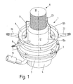
In der Fig. 1 bedeutet 1 einen Brenner, der ein durch einen Flansch 2 gehaltenes Gebläse 3
aufweist, dem durch einen Anschlußschlauch 10 Frischluft zuführbar ist. Unterhalb des
Gebläses 3 ist ein Motor 4 angeordnet, der das Gebläse 3 antreibt. Auf das Gebläse 3 ist
ein Brennertopf 5 aufgesetzt, der auf seiner Oberseite mit einem Anschlußflansch 6
versehen ist, mit dem der Brenner 1 von unten an einem nicht dargestellten Heizkessel
montierbar ist. Oben am Gebläse 3 ist ein Brennstoffanschluß 7 vorgesehen. Hier wird dem
Brenner 1 das Heizöl zugeführt. Vom Brennstoffanschluß 7 gelangt das Heizöl über eine in
dieser Ansicht nicht sichtbare Brennstoffleitung in eine in dieser Ansicht ebenfalls nicht
sichtbare Verdampferkammer. In der Wand des Brennertopfes 5 ist ein Temperaturfühler 8
montiert, der in Verbindung mit einem nicht dargestellten Regler der Regelung der
eingangs schon erwähnten elektrischen Heizeinrichtung dient. Zusätzlich wird die Wand
des Brennertopfes 5 von einer ersten Halterung 26 durchstoßen, die der Aufnahme einer
Zündvorrichtung, beispielsweise einer Zündelektrode 9 oder eines Glühzünders, dient.
Diese der Zündung des Brennstoff-Luft-Gemisches dienende Zündelektrode 9 ist so
ausgerührt, daß ihr eines Ende in jenen Bereich des Brenners 1 ragt, in dem die Flamme
entstehen soll. Dieser Bereich ist gegeben durch einen zylindrischen Flammenhalter 11, der
aus einem Umlenkkragen 12 herausragt und der an seiner Oberseite mit einem Deckel 35
verschlossen ist. Der Umlenkkragen 12 besteht aus einem zylindrischen Teil 12a und einem
daran anschließenden schrägen Ansatz 12b. Der Flammenhalter 11 ist auf die in dieser
Darstellung nicht sichtbare Verdampferkammer aufgesetzt. Er besteht vorteilhaft aus
hitzebeständigem Stahl oder Keramik. Der Umlenkkragen 12 besteht vorteilhaft aus
hitzebeständigem Stahlblech, allenfalls auch aus Stahlguß.In Fig. 1, 1 means a burner having a
Die Fig, 1 zeigt weiter eine Elektrode 23, die in der Wand des Brennertopfes 6 mittels
einer weiteren Halterung 22 befestigt ist. Das freie Ende dieser Elektrode 23 liegt in einem
gewissen Abstand parallel zur Oberfläche des Flammenhalters 11. Die Elektrode 23 gehört
zu einer nicht dargestellten Ionisationsmeßeinrichtung, mit der das Vorhandensein einer
Flamme überwachbar ist. Diese Überwachung erfolgt durch ein dem Brenner 1
zugeordnetes, hier aber nicht dargestelltes Brenner-Steuergerät, das wie beim Stand der
Technik Start und Betrieb des Brenners 1 steuert und überwacht.FIG. 1 further shows an
Fig. 2 zeigt einen Vertikalschnitt durch den in der Fig. 1 gezeigten Brenner 1, aus dem
mehr Einzelheiten erkennbar sind. Dargestellt ist dabei eine erste Ausführungsform des
Brenners 1. Im unteren Teil der Fig. 2 ist der Motor 4 erkennbar, der das Gebläse 3
(Fig. 1) antreibt. In dieser Darstellung ist vom Gebläse 3 nur eine Motor 4 und Gebläse 3
gemeinsame Antriebswelle 14 erkennbar, auf der ein erster Rotor 15 und ein zweiter
Rotor 16 befestigt sind. Durch die Rotoren 15, 16 wird Frischluft gefördert, wobei die
Förderrichtung mit Pfeilen gekennzeichnet ist.FIG. 2 shows a vertical section through the burner 1 shown in FIG
more details are recognizable. Shown here is a first embodiment of the
Burner 1. In the lower part of Fig. 2, the
Im oberen Teil der Fig. 2 ist der Flammenhalter 11 mit seinem Deckel 35 erkennbar, wobei
auch ersichtlich ist, daß der Flammenhalter 11 auf einer im Zusammenhang mit der Fig. 1
schon erwähnten Verdampferkammer 17 aufsitzt. Nach unten ist die
Verdampferkammer 17 von einem Boden 19 verschlossen. Der von der
Verdampferkammer 17 und seinem Boden 19 umschlossene Raum bildet eine Misch- und
Verdampferzone 18. In die Wandung der Verdampferkammer 17 ist eine elektrische
Heizeinrichtung 20 integriert.In the upper part of Fig. 2, the
Der Flammenhalter 11 ist umgeben von einem Feuerraum 21. In diesem Raum brennt die
Flamme. Der zylindrische Mantel des Flammenhalters 11 besteht aus mindestens einem,
vorteilhaft aber aus zwei ineinander gefügten Lochblechen, nämlich einem äußeren
Lochblech 24 und einem inneren Lochblech 25. Die in diesen Lochblechen 24, 25
vorhandenen Öffnungen können kreisrund oder länglich sein, also beispielsweise auch als
Schlitze ausgebildet sein. Daneben sind andere Formen möglich. Die Öffnungen der beiden
Lochbleche 24, 25 können unterschiedlich groß sein. Beispielsweise können die Löcher im
äußeren Lochblech 24 kleiner sein als jene im inneren Lochblech 25. Auch das Lochraster
kann unterschiedliche Maße haben. Vorteilhaft kann es außerdem sein, daß die Größe der
Öffnungen variiert, indem beispielsweise die Öffnungen im unteren, der
Verdampferkammer 17 zugewandten Bereich größer sind und die Größe der Öffnungen
nach oben hin, also in Richtung des Deckels 35 hin, abnimmt. Die aus den beiden
Lochblechen 24, 25 gebildeten Zylinder können unmittelbar ineinander geschoben sein,
doch kann zwischen ihnen vorteilhaft auch ein mehr oder weniger großer Spalt vorhanden
sein. An den Öffnungen des äußeren Lochblechs 24 brennen kleine Teilflammen, die
zusammen einen sehr stabilen Flammenteppich bilden. Durch das innere Lochblech 25 wird
erreicht, daß die Vermischung von Brennstoff und Luft nochmals verbessert wird.
Zusätzlich wird erreicht, daß das innere Lochblech 25 eine deutlich niedrigere Temperatur
aufweist als das äußere Lochblech 24. Durch diese Maßnahme ist ein Zurückschlagen der
Flamme in das Innere des Flammenhalters 11 weitestgehend ausgeschlossen. Die
angegebenen Bauformen des Flammenhalters 11 haben auch den Vorteil, daß die Flamme
sehr gleichmäßig brennt, was sich auch in einem niedrigen Geräuschpegel äußert.The
Der einen Teil des Flammenhalters 11 umgebende Umlenkkragen 12 reicht mit seinem
zylindrischen Teil 12a nicht bis züm Boden des Brennertopfes 5 (Fig. 1), sondern ist unten
mittels beispielsweise dreier nicht dargestellter Beine im Brennertopf 5 gehalten. Der
schräge Ansatz 12b des Umlenkkragens 12 reicht nicht bis an den zylindrischen Mantel des
Flammenhalters 11 heran. Vielmehr bleibt dazwischen ein Ringspalt 34 offen.The surrounding part of the
Unterhalb des Flammenhalters 11 ist in der Verdampferkammer 17 eine Lochscheibe 27
angeordnet, die parallel zum Boden 19 der Verdampferkammer 17 liegt. Zwischen dieser
Lochscheibe 27 und dem Boden 19 befindet sich ein Mischrad 28, das auf der
Antriebswelle 14 befestigt ist. Dieses Mischrad 28 rotiert also zusammen mit den
Rotoren 15, 16. Unterhalb des Mischrads 28 ist ein Leitblech 29 angeordnet. Weiter
unterhalb ist mit der Antriebswelle 14 ein konischer Zerstäuberbecher 30 verbunden, in
dessen Innenraum ein Ende 31 einer Brennstoffleitung 32 hineinragt. Da auch das
Leitblech 29 und der Zerstäuberbecher 30 auf der Antriebswelle 14 befestigt sind, drehen
sich diese Teile gemeinsam mit den Rotoren 15, 16 und dem Mischrad 28. Der
Vollständigkeit halber sei erwähnt, daß zwischen den Boden 19 und dem Gehäuse des
darunter liegenden Gebläses 3 (Fig. 1) eine kreisringförmige Dichtung 33 liegt.Below the
Nachstehend wird nun die Funktionsweise des Brenners 1 beschrieben. Dabei wird
zunächst von einem Zustand ausgegangen, bei dem der Brenner 1 abgeschaltet und
weitestgehend abgekühlt ist. Von einem übergeordneten Heizungsregler oder Kesselregler
wird nun dem Brenner-Steuergerät ein Befehl übermittelt, daß der Brenner 1 eingeschaltet
werden soll. Das Prozedere der Inbetriebsetzung entspricht dem bekannten Stand der
Technik. Erfindungsgemäß ist nun vorgesehen, daß das Brenner-Steuergerät zunächst die
elektrische Heizeinrichtung 20 einschaltet. Damit wird die Verdampferkammer 17 mittels
Fremdenergie geheizt. Durch das Einschalten des Gebläses 3 rotieren die mit der
Antriebswelle 14 verbunden Teile wie Rotoren 15, 16, Mischrad 28, Leitblech 29 und
Zerstäuberbecher 30. Nach Ablauf einer Vorzündzeit wird eine Förderpumpe, die das zur
Verbrennung kommende Heizöl aus einem Tank in den Brenner 1 fördert, in Betrieb
gesetzt.The operation of the burner 1 will now be described. It will
initially assumed a state in which the burner 1 is turned off and
has largely cooled. From a higher-level heating controller or boiler controller
Now the burner control unit is transmitted a command that the burner 1 is turned on
shall be. The procedure of commissioning corresponds to the known state of
Technology. According to the invention it is now provided that the burner control unit first the
Durch die Inbetriebsetzung der Förderpumpe wird nun Heizöl durch den
Brennstoffanschluß 7 (Fig. 1) in die Brennstoffleitung 32 gefördert, an dessen Ende 31 es
austritt. Das geforderte Heizöl fließt oder tropft auf die innere Wandung des
Zerstäuberbechers 30. Wegen der Drehung des Zerstäuberbechers 30 fließt das Heizöl
unter Wirkung der Zentrifugalkraft gegen den oberen Rand des Zerstäuberbechers 30, wird
dort vom Rand weggeschleudert und trifft auf die Innenwand der Verdampferkammer 17.
Gleichzeitig wird durch die Rotoren 15, 16 des Gebläses 3 Frischluft gefördert, die von
unten auf den Zerstäuberbecher 30 trifft. Die Frischluft strömt dabei einerseits außen am
Zerstäuberbecher 30 entlang, andererseits aber auch durch Öffnungen im Boden des
Zerstäuberbechers 30 durch das Innere des Zerstäuberbechers 30 gegen das Leitblech 29.
Beide Teilströme fließen dann um das Mischrad 28 und das Leitblech 29 herum. In der Fig.
2 ist dies mit Pfeilen angedeutet. Je nach Wärmeanforderung ist die Drehzahl der
Förderpumpe kleiner oder größer, wobei die Drehzahlen von Förderpumpe und Gebläse 3
aufeinander abgestimmt sind, damit die Mengen von Brennstoff und Luft so aufeinander
abgestimmt sind, daß eine möglichst vollständige Verbrennung stattfindet. Ist die
Förderpumpe beispielsweise keine Zahnradpumpe, sondern eine Kolbenpumpe, tritt an die
Stelle der Drehzahl eine andere das Fördervolumen kennzeichnende Größe. Wesentlich ist,
daß die geforderten Volumina von Luft und Brennstoff in einem richtigen Verhältnis
stehen.By commissioning the pump is now fuel oil through the
Fuel port 7 (Fig. 1) conveyed into the
Durch die Wirkung der elektrischen Heizeinrichtung 20 ist die Verdampferkammer 17
vorgewärmt, so daß hier nun das durch die Zerstäubung schon fein verteilte Heizöl
verdampft und gleichzeitig mit der durchströmenden Frischluft intensiv vermischt wird.
Das brennbare Gemisch aus Heizöldampf und Luft, das infolge abgestimmter Drehzahlen
von Förderpumpe und Gebläse 3 annähernd stöchiometrisch zusammengesetzt ist, tritt nun
in den Innenraum des Flammenhalters 11 ein, was in der Fig. 2 ebenfalls durch Pfeile
gekennzeichnet ist. Anschließend tritt dieses Gemisch durch die Löcher in den
Lochblechen 24, 25 hindurch. Vom Brenner-Steuergerät wird zum geeigneten Zeitpunkt
die Zündung eingeschaltet. Die Zündelektrode 9 steht unter Spannung und zündet das
brennbare Gemisch. Nun brennt an der Mantelfache des Flammenhalters 11 eine
zusammenhängende Flamme und die heißen Abgase strömen in den Feuerraum 21. Der
Feuerraum 21 ist vom Wärmetauscher des Heizkessels umgeben, was in den Fig. 1 und 2
nicht dargestellt ist.By the action of the
Erfindungsgemäß ist nun vorgesehen, einen Teil des Stroms der heißen Abgase durch
geeignete Mittel derart umzulenken, daß sie die Verdampferkammer 17 von außen
beheizen. In den Fig. 1 und 2 sind diese Mittel in der Form des Umlenkkragens 12
dargestellt. Andere, gleich wirkende Ausführungen sind im Rahmen der Erfindung
möglich. Jene heißen Abgase, die im vom Umlenkkragen 12 umgebenen Raum am
Flammenhalter 11 entstehen, werden durch den Umlenkkragen 12 nach unten gelenkt, was
in der Fig. 2 wiederum mit Pfeilen gekennzeichnet ist. Die heißen Abgase wirken somit
von außen auf die Verdampferkammer 17 und heizen diese auf. Damit wird
erfindungsgemäß der weitere Betrieb der elektrischen Heizeinrichtung 20 entbehrlich.
Vorteilhaft ist am Brennertopf 5 (Fig. 1) der Temperaturfühler 8 montiert. Mit Hilfe dieses
Temperaturfühlers 8 wird ermittelt, ob im Brennertopf 5 und damit an der
Verdampferkammer 17 die zur Verdampfung des Heizöls erforderliche Temperatur, bei
Heizöl extra leicht mindestens 350 Grad Celsius, erreicht ist. Der Temperaturfühler 8
ermittelt also den Istwert der Temperatur und gibt diesen Meßwert an das Brenner-Steuergerät
ab, das den Istwert der Temperatur mit einem Sollwert vergleicht und das
dann, wenn der Istwert höher ist als der Sollwert, die elektrische Heizeinrichtung 20
abschaltet.According to the invention is now provided, a portion of the flow of hot exhaust gases through
to redirect suitable means such that they the
Der Temperaturfühler 8 kann zusammen mit dem Brenner-Steuergerät und der
elektrischen Heizeinrichtung 20 auch so wirken, daß die Temperatur in der
Verdampferkammer 17 nicht nur beim Erreichen einer bestimmten Temperatur
abgeschaltet wird, sondern daß die Temperatur in der Verdampferkammer 17 echt geregelt
wird, z.B. nach einem PID-Algorithmus. Dies kann von Vorteil sein, wenn der Brenner in
einer extrem kalten Klimazone eingesetzt wird.The temperature sensor 8, together with the burner control unit and the
An sich wäre es auch möglich, die elektrische Heizeinrichtung 20 eine bestimmte, zum
Beispiel einstellbare Zeit nach dem Erscheinen der Flamme abzuschalten. Die Lösung mit
dem durch den Temperaturfühler 8 gesteuerten Abschalten ist jedoch hinsichtlich
Betriebssicherheit und Effizienz vorteilhaft. Damit paßt sich die Abschaltung der
elektrischen Heizeinrichtung 20 auch automatisch an die effektive Heizleistung des
Brenners 1 an, wenn dieser modulierend, also mit kleinerer oder größerer Leistung,
betrieben wird.As such, it would also be possible for the
Durch die Dimensionierung von Flammenhalter 11 und Umlenkkragen 12 läßt sich
bestimmen, welcher Teil der heißen Abgase zur Aufheizung der Verdampferkammer 17
herangezogen wird. Der Ringspalt 34 bewirkt, daß an der Mantelfläche des
Flammenhalters 11 eine durchgehende Flamme besteht. Durch die Öffnungen in den
Lochblechen 24, 25, die funktionell der in DE-A1-25 34 066 beschriebenen
Flammenlochplatte entspricht, wird auch erreicht, daß die Flamme stabil brennt und nicht
zurückschlagen kann.By dimensioning of
Durch die erfindungsgemäße Einrichtung wird sichergestellt, daß in der
Verdampferkammer 17 die zur vollständigen Verdampfung des Heizöls notwendige
Temperatur herrscht, so daß ausgeschlossen werden kann, daß das Heizöl verkokt und den
Brenner 1 verschmutzt und störungsanfällig macht.By the device according to the invention it is ensured that in the
Die große Mantelfläche des Flammenhalters 11 hat zudem den Vorteil, daß eine
großflächige Flamme entsteht, deren Temperatur kleiner ist als bei Brennern nach dem
Stand der Technik. Dies wirkt sich vorteilhaft aus, weil beim erfindungsgemäßen
Brenner 1 weniger Stickoxide NOx entstehen. Vorteilhaft ist weiter, daß bei einem solchen
Brenner 1 nur kleine Druckdifferenzen, sowohl auf der Brennstoff-, wie auch auf der
Luftseite, nötig sind, was sich positiv in einem geringen Geräuschpegel äußert. Der
erfindungsgemäße Brenner 1 läßt sich deshalb problemlos auch bei Etagenheizungen
einsetzen, wo sonst üblicherweise Gasbrenner wegen des diesem Brennertyp eigenen
niedrigen Geräuschpegels bevorzugt werden.The large lateral surface of the
Im Zusammenhang mit dem erfindungsgemäßen Brenner 1 sind zur Förderung des Heizöls unterschiedliche Bauarten von Pumpen einsetzbar, beispielsweise Kolben- oder Zahnradpumpen, weil keine Druckzerstäubung des Heizöls erforderlich ist, was hohe Öldrücke erfordern würde.In connection with the burner 1 according to the invention are for the promotion of fuel oil different types of pumps used, such as piston or Gear pumps, because no pressure atomization of the fuel oil is required, which is high Would require oil pressures.
In der Fig. 3 ist ein Vertikalschnitt einer zweiten Ausführungsform dargestellt. Gleiche
Teile sind dabei mit gleichen Bezugszahlen versehen. Vorteilhaft ist bei diesem
Ausführungsbeispiel zentral im Innenraum des Flammenhalters 11 ein Einsatz 36
angeordnet, der aus wärmebeständigem Stahlblech besteht. Der Einsatz 36 ist
rotationssymmetrisch und besteht aus einem kegelstumpfförmigen Oberteil 37 und einem
daran anschließenden kegelförmigen Unterteil 38. Wie beim vorangehenden
Ausführungsbeispiel strömt auch bei dieser Variante das Brennstoff-Luft-Gemisch von
unten in den Innenraum des Flammenhalters 11 ein. Durch den Einsatz 36 wird das vom
Brennstoff-Luft-Gemisch im Inneren des Flammenhalters 11 ausgefüllte Volumen
verkleinert und durch die Formgestaltung des Einsatzes 36 wird erreicht, daß der effektiv
wirksame Querschnitt im Flammenhalter 11 von unten nach oben abnimmt. Durch diese
Maßnahmen wird erreicht, daß das Totvolumen im Flammenhalter 11 kleiner ist, und daß
sich die mittlere Strömungsgeschwindigkeit erhöht, wodurch die Verweilzeit des
Brennstoff-Luft-Gemisches im Inneren des Flammenhalters 11 reduziert wird. Diese
Maßnahmen führen auch dazu, daß trotz der im Brennerbetrieb stattfindenden Aufheizung
die Neigung zur Selbstzündung innerhalb des Flammenhalters 11 nochmals vermindert
wird. Auch bei längerem Vollast-Betrieb wird so ein Flammenrückschlag verhindert. Die
beschriebene Formgestaltung des Einsatzes 36 ist nur als Beispiel zu verstehen. Andere
Ausführungsformen, beispielsweise mit einem parabelförmigen Verlauf, sind im Rahmen
der Erfindung vorteilhaft möglich.FIG. 3 shows a vertical section of a second embodiment. Same
Parts are provided with the same reference numbers. It is advantageous in this
Embodiment centrally in the interior of the
Fig. 3 zeigt darüber hinaus eine andere Ausführung im Inneren der Verdampferkammer,
die hier im Unterschied zur Fig. 2 mit der Bezugszahl 39 versehen ist. Diese
Ausführungsform unterscheidet sich vor jener nach Fig. 2 auch dadurch, daß Leitblech 29,
Mischrad 28 und Lochscheibe 27 fehlen. Dadurch ergibt sich eine modifizierte Bereitung
des Brennstoff-Luft-Gemisches. Vom sich drehenden Zerstäuberbecher 30 wird das Heizöl
unter der Wirkung der Zentrifugalkraft gegen die Innenwand der Verdampferkammer 39
geschleudert, worauf es dort verdampft. Das verdampfte Heizöl wird durch einen ersten
Teilstrom der vom Gebläse 3 (Fig. 1) geförderten Luft, die durch einen Spalt 40 außen am
Zerstäuberbecher 30 vorbeigeführt wird, mitgenommen, wobei sich der Teilstrom der Luft
und der Dampf des Heizöls vermischen. Gleichzeitig wird dieser Teilstrom der Luft in der
Verdampferkammer 39 erwärmt. Ein zweiter Teilstrom strömt vom Gebläse 3 (Fig. 1)
durch das Innere des unten auch hier offenen Zerstäuberbechers 30 und bleibt unerwärmt
und kühlt damit die Verdampferkammer 39 nicht ab. Oberhalb des Zerstäuberbechers 30
vereinigen sich die beiden Teilströme, so daß erst hier eine vollständige Vermischung von
Brennstoff und Luft erfolgt. Im Brenner 1 lassen sich also eine Luftzufuhrzone 42, eine
Verdampferzone 43 und eine Mischzone 41 deutlich gegeneinander abgrenzen. Während
die Luftzufuhrzone 42 durch das Gebläse 3 gebildet wird, umfaßt die Verdampferzone 43
den Zerstäuberbecher 30 und den Innenraum der Verdampferkammer 39. Die eigentliche
Mischzone 41 wird hier vom Innenraum des Flammenhalters 11 gebildet, wobei die
Durchmischung von Brennstoff und Luft auch dadurch verbessert wird, daß bei diesem
Ausführungsbeispiel zwischen dem äußeren Lochblech 24 und dem inneren Lochblech 25
ein deutlicher Abstand besteht.3 also shows another embodiment inside the evaporator chamber,
which is provided here in contrast to FIG. 2 with the
Im Gegensatz zum Beispiel der Fig. 1 wird dem Gebläse 3 die Luft nicht über einen
Anschlußschlauch 10 zugeführt, sondern die Luft kann über eine Öffnung 44 im Gehäuse
des Gebläses 3 aus der unmittelbaren Umgebung des Brenners 1 einströmen. Es kann aber
auch ein Anschlußschlauch 10 (Fig. 1) vorgesehen sein.In contrast to the example of Fig. 1, the
In der Fig. 3 ist zudem näher gezeigt, wie der Brenner 1 an einem Heizkessel 50
befestigbar ist. Der Brennertopf, in der Fig. 1 mit der Bezugszahl 5 versehen, ist hier mit
der Bezugszahl 45 bezeichnet. An seinem oberen Ende weist der Brennertopf 45 einen
Flansch 46 auf, dessen äußeres Ende 47 nach unten umgebogen ist. Ein Spannring 48
umschließt das äußere Ende 47 des Brennertopfes 45 und gleichzeitig einen Ansatz 49 am
Heizkessel 50. Auf der linken Seite der Fig. 3 ist zudem im Sinne eines Beispiels gezeigt,
wie die Befestigung des Brenners 1 am Heizkessel 50 eindeutig positionierbar ausgeführt
ist. Vom äußeren Ende 47 des Flansches 46 ist ein Lappen 51 nach oben gebogen, der in
eine Aussparung 52 im Ansatz 49 des Heizkessels 50 eingreift.In Fig. 3 is also shown in more detail how the burner 1 to a boiler 50th
is fastened. The burner pot, provided in FIG. 1 with the
In der Fig. 4 sind alternative Ausführungsvarianten gezeigt, mit denen erfindungsgemäß
eine Beeinflussung jenes Teilstroms der heißen Abgase möglich ist, mit denen, wie bei der
Erläuterung der Fig. 2 erwähnt, die Verdampferkammer 17 von außen heizbar ist. Es hat
sich als vorteilhaft herausgestellt, wenn Mittel vorhanden sind, um diesen Teilstrom zu
beeinflussen, um die Temperatur der Verdampferkammer 17 unter allen Lastbedingungen
etwa konstant zu halten. Die erste Ausführungsvariante betrifft die Ausführung des
schrägen Ansatzes 12b des Umlenkkragens 12. Dieser besteht vorteilhaft aus
Thermobimetall, so daß er mit einer Temperaturänderung seine Form verändert, indem er
sich wölbt. Eine durch eine solche Temperaturänderung erzielbare zweite Stellung ist in
der Fig. 4 mit der Bezugszahl 12b' dargestellt. Durch diese Formänderung ändert sich bei
Temperaturänderung die Breite des Ringspaltes 34, was auf die Größe des Teilstroms der
heißen Abgase Einfluß hat.In Fig. 4 alternative embodiments are shown with which according to the invention
an influence of that partial flow of hot exhaust gases is possible with which, as in the
Explanation of Fig. 2 mentioned, the
Damit der schräge Ansatz 12b des Umlenkkragens 12 diese Wölbung möglichst
ungehindert bilden kann, ist es vorteilhaft, wenn er geschlitzt ist. In der Fig. 5 ist der
schräge Ansatz 12b dargestellt, der Schlitze 55 aufweist.Thus, the
Eine zweite Variante für die Beeinflussung des Teilstroms der heißen Abgase besteht
darin, daß ein Abschnitt 56 des zylindrischen Teils 12a des Umlenkkragens 12 aus
Thermobimetall besteht. Wenn sich dieser Abschnitt 56 durch Hitzeeinwirkung verwölbt,
entsteht im zylindrischen Teil 12a eine Ableitöffnung 57, durch die ein Teil des Teilstroms
der heißen Abgase wieder austreten kann, so daß er keinen thermischen Einfluß auf die
Verdampferkammer 17 ausüben kann. Damit wird bei sehr heißen Abgasen die
Verdampferkammer 17 weniger stark erwärmt. Um die möglichst ungehinderte
Verwölbung des Abschnitts 56 zu ermöglichen, ist dieser Abschnitt 56 ebenfalls geschlitzt.A second variant for influencing the partial flow of hot exhaust gases exists
in that a
Eine dritte Variante besteht darin, daß um die äußere Mantelfläche der
Verdampferkammer 17 ein Kragen 58 gelegt ist, der ebenfalls aus Thermobimetall besteht.
Auch dieser Kragen 58 verwölbt sich unter Hitzeeinwirkung. Damit wird die Größe des
freien Querschnitts zwischen Verdampferkammer 17 und dem zylindrischen Teil 12a des
Umlenkkragens 12 verändert, was sich unmittelbar auf den Teilstrom der heißen Abgase
auswirkt, der die Verdampferkammer 17 thermisch beeinflußt.A third variant is that around the outer surface of the
Die verschiedenen zuvor beschriebenen Ausführungsvarianten können auch kombiniert werden. So kann beispielsweise der Einsatz 36 auch bei der ersten Ausführungsform nach Fig. 2 angewendet werden.The various embodiments described above can also be combined become. For example, the insert 36 can also be used in the first embodiment Fig. 2 are applied.
Im den Flammenhalter 11 umgebenden Feuerraum 21 kann vorteilhaft eine den
Flammenhalter 11 konzentrisch umschließende, in den Figuren nicht dargestellte Spirale
angeordnet sein, die die Aufgabe hat, Wärme aus der Flamme abzuleiten. Mit dieser
Maßnahme wird erreicht, daß die Flammentemperatur niedriger wird, was sich vorteilhaft
in einem geringeren Gehalt an Stickoxiden NOx äußert. In the
Die vorstehend beschriebenen Varianten des Brenners 1 sind im Verhältnis von 1:3 modulierbar, so daß die Leistung des Brenners 1 beispielsweise zwischen 5 und 15 kW steuerbar ist.The variants of the burner 1 described above are in the ratio of 1: 3 modulated, so that the power of the burner 1, for example, between 5 and 15 kW is controllable.
Claims (11)
- A burner (1) which can be activated by a burner control unit and is intended for liquid fuel, in particular for extra light heating oil, to which burner (1) a fan (3) driven by a motor (4) is assigned, and which has a burner pot (5, 45) having a vaporizing chamber (17, 39), an atomizer element (30, 28) placed in the vaporizing chamber (17, 39), and an electric heating device (20), a cylindrical flame retention baffle (11) being put onto the vaporizing chamber (17, 39), and the flame forming on the lateral surface of this flame retention baffle (11) during burner operation, the lateral surface being provided with holes, and in which there is a temperature sensor (8), the signal of which is fed to the burner control unit, which thereupon determines whether it is necessary to switch on the electric heating device (20), characterizedin that there are means (12) with which a portion of the flow of the hot exhaust gases is deflected in such a way that said portion heats the vaporizing chamber (17, 39) from outside in such a way that a temperature of at least 350 degrees Celsius is reached in the vaporizing chamber (17, 39),in that the temperature sensor (8) is attached in the wall of the burner pot (5, 45), andin that the electric heating device (20), which is switched on when the burner (1) is being started, is switched off by the burner control unit as soon as the actual value of the temperature measured by the temperature sensor (8) on the burner pot (5, 45) exceeds a desired value which can be set in the burner control unit.
- The burner as claimed in claim 1, characterized in that the means for deflecting a portion of the flow of the hot exhaust gases are formed by a deflection collar (12) which concentrically encloses a part of the flame retention baffle (11).
- The burner as claimed in claim 2, characterized in that the air flow delivered by the fan (3) is split up into a first partial flow and a second partial flow upstream of the vaporizing chamber (17, 39), the first partial flow being mixed with the fuel vaporized in the vaporizing chamber (17, 39), while the second partial flow is directed through the interior of an atomizer cup (30) belonging to the atomizer element (30, 28), so that this partial flow does not cool the vaporizing chamber (17, 39).
- The burner as claimed in one of claims 1 to 3, characterized in that the lateral surface of the flame retention baffle (11) is formed by a perforated plate (24, 25), while the flame retention baffle (11) is closed on its top side by a cover (35).
- The burner as claimed in claim 4, characterized in that a second perforated plate (25) is arranged inside a first perforated plate (24) forming the lateral surface of the flame retention baffle (11).
- The burner as claimed in claim 5, characterized in that the holes in the outer perforated plate (24) are smaller than those in the inner perforated plate (25).
- The burner as claimed in one of claims 4 to 6, characterized in that the flame retention baffle (11) is made of heat-resistant steel sheet or ceramic.
- The burner as claimed in one of claims 2 to 7, characterized in that there is an annular gap (34) between the lateral surface of the flame retention baffle (11) and the deflection collar (12).
- The burner as claimed in claim 8, characterized in that there are means (12b, 55) for changing the size of the annular gap (34) and/or means (56, 57; 58) for influencing the deflected portion of the flow of the hot exhaust gases as a function of the temperature of the exhaust gases.
- The burner as claimed in one of claims 2 to 9, characterized in that a rotationally symmetrical insert (36) is arranged centrally in the interior space of the flame retention baffle (11), by means of which insert (36) the effective cross section in the interior space of the flame retention baffle (11) decreases from bottom to top.
- The burner as claimed in claim 10, characterized in that the insert (36) consists of a frustoconical top part (37) and an adjoining conical bottom part (38).
Applications Claiming Priority (3)
| Application Number | Priority Date | Filing Date | Title |
|---|---|---|---|
| CH178398 | 1998-09-01 | ||
| CH178398 | 1998-09-01 | ||
| PCT/CH1999/000376 WO2000012935A1 (en) | 1998-09-01 | 1999-08-13 | Burner for liquid fuel |
Publications (2)
| Publication Number | Publication Date |
|---|---|
| EP1110033A1 EP1110033A1 (en) | 2001-06-27 |
| EP1110033B1 true EP1110033B1 (en) | 2004-02-25 |
Family
ID=4218508
Family Applications (1)
| Application Number | Title | Priority Date | Filing Date |
|---|---|---|---|
| EP99936224A Expired - Lifetime EP1110033B1 (en) | 1998-09-01 | 1999-08-13 | Burner for liquid fuel |
Country Status (9)
| Country | Link |
|---|---|
| US (1) | US6540505B1 (en) |
| EP (1) | EP1110033B1 (en) |
| AT (1) | ATE260442T1 (en) |
| AU (1) | AU5145599A (en) |
| CA (1) | CA2341549C (en) |
| DE (2) | DE59908661D1 (en) |
| DK (1) | DK1110033T3 (en) |
| HR (1) | HRP20010143A2 (en) |
| WO (1) | WO2000012935A1 (en) |
Cited By (2)
| Publication number | Priority date | Publication date | Assignee | Title |
|---|---|---|---|---|
| DE202009018149U1 (en) | 2009-10-01 | 2011-03-03 | Viessmann Werke Gmbh & Co Kg | Burner for liquid fuel |
| DE102009043681A1 (en) | 2009-10-01 | 2011-04-07 | Viessmann Werke Gmbh & Co Kg | Burner for liquid fuel, has air circulation and heating chamber connected to heat exchanger and provided upstream to evaporation and mixing chamber for heating air, where heat exchanger is formed as exhaust air heat exchanger |
Families Citing this family (16)
| Publication number | Priority date | Publication date | Assignee | Title |
|---|---|---|---|---|
| AT408904B (en) * | 2000-06-07 | 2002-04-25 | Windhager Zentralheizung Ag | EVAPORATOR CHAMBER FOR OIL EVAPORATOR PRE-MIX BURNER |
| EP1523539A1 (en) * | 2002-07-19 | 2005-04-20 | Shell Internationale Researchmaatschappij B.V. | Process to generate heat |
| CH696152A5 (en) | 2003-06-04 | 2007-01-15 | Toby Ag | Liquid-fuelled central heating system burner chamber has insert sub-dividing burner chamber into sectors and attached to burner base |
| CH696212A5 (en) | 2003-06-04 | 2007-02-15 | Toby Ag | Evaporator burner is for liquid fuel and incorporates evaporation chamber in which is rotating atomizer disk |
| CH696153A5 (en) | 2003-06-11 | 2007-01-15 | Toby Ag | Burner for liquid fuels. |
| US8070480B2 (en) * | 2003-11-21 | 2011-12-06 | Associated Physics Of America, Llc | Method and device for combusting liquid fuels using hydrogen |
| GB2443429A (en) * | 2005-09-24 | 2008-05-07 | Siemens Ind Turbomachinery Ltd | Fuel Vaporisation Within a Burner Associated With a Combustion Chamber |
| CH700427B1 (en) | 2007-09-12 | 2010-08-31 | Thermmix Ag | A method of controlling an evaporative burner. |
| ITMI20071751A1 (en) | 2007-09-12 | 2009-03-13 | Polidoro S P A | PREMIXED BURNER |
| CH700919B1 (en) | 2007-10-01 | 2010-11-15 | Toby Ag | Burner with an evaporator chamber. |
| WO2014024942A1 (en) * | 2012-08-07 | 2014-02-13 | 日野自動車 株式会社 | Burner |
| WO2014027596A1 (en) | 2012-08-13 | 2014-02-20 | 日野自動車 株式会社 | Burner |
| EP2837884B1 (en) * | 2012-11-06 | 2016-08-03 | Hino Motors, Ltd. | Burner |
| CN103411228B (en) * | 2013-07-19 | 2016-05-25 | 福建省三明长兴机械制造有限公司 | A kind of high-efficient energy-saving kiln tubular type vaporising device and control method thereof |
| CN104154535B (en) * | 2014-08-07 | 2016-03-23 | 长治市宏达康工贸有限公司 | The ethanol combustor that a kind of Blower-free is combustion-supporting |
| US10684019B2 (en) * | 2015-11-17 | 2020-06-16 | Whirlpool Corporation | Electric warming element for gas burner |
Family Cites Families (19)
| Publication number | Priority date | Publication date | Assignee | Title |
|---|---|---|---|---|
| US3734677A (en) * | 1970-08-12 | 1973-05-22 | Matsushita Electric Ind Co Ltd | Liquid fuel burner |
| GB1520402A (en) | 1974-07-30 | 1978-08-09 | Mitsubishi Electric Corp | Combustion apparatus |
| CA1133821A (en) * | 1978-06-28 | 1982-10-19 | Hajime Satoda | Combustion apparatus |
| US4280806A (en) * | 1979-08-14 | 1981-07-28 | King Paul C | Prevaporizing oil burner and method |
| JPS5630520A (en) * | 1979-08-20 | 1981-03-27 | Matsushita Electric Ind Co Ltd | Safety device for combusting apparatus |
| US4303055A (en) * | 1980-01-07 | 1981-12-01 | Stanley Fixler | Waste oil heater having fuel control system |
| JPS5831208A (en) * | 1981-08-19 | 1983-02-23 | Matsushita Electric Ind Co Ltd | Combustion apparatus for liquid fuel |
| US4504215A (en) * | 1981-10-09 | 1985-03-12 | Nippon Gakki Seizo Kabushiki Kaisha | Liquid fuel burner |
| JPS58200911A (en) * | 1982-05-17 | 1983-11-22 | Inax Corp | Combustion method for liquid fuel and device therefor |
| JPS58208510A (en) * | 1982-05-28 | 1983-12-05 | Toyotomi Kogyo Co Ltd | Ignition device for kerosene burner |
| NL8300028A (en) * | 1983-01-05 | 1984-08-01 | Conma Nv | PROCESS FOR CONTROLLING FUEL SUPPLY AND BURNER. |
| KR890000327B1 (en) * | 1984-04-19 | 1989-03-14 | 도오도오 기기 가부시기가이샤 | Method and apparatus for gasifying and combusting liquid fuel |
| JPS61235612A (en) * | 1985-04-11 | 1986-10-20 | Toyotomi Kogyo Co Ltd | Safety device for burner |
| EP0232677B1 (en) * | 1985-12-30 | 1989-08-09 | VTH AG Verfahrenstechnik für Heizung | Burner, particularly burner for burning liquid fuel in gaseous state |
| DE3709830A1 (en) * | 1987-03-25 | 1988-10-06 | Gerhard Weinbrenner | Combustion tube, for oil-fired central-heating boilers in particular |
| FR2665942B1 (en) | 1990-08-14 | 1996-04-12 | Samsung Electronics Co Ltd | ROTARY HEATING APPARATUS WITH FORCED CONVEXION. |
| US5328355A (en) * | 1991-09-26 | 1994-07-12 | Hitachi, Ltd. | Combustor and combustion apparatus |
| ATE142324T1 (en) * | 1992-02-28 | 1996-09-15 | Fuellemann Patent Ag | BURNER, ESPECIALLY OIL BURNER OR COMBINED OIL/GAS BURNER |
| FR2733579B1 (en) * | 1995-04-25 | 1998-08-14 | Samsung Electronics Co Ltd | KEROSENE COMBUSTION DEVICE |
-
1999
- 1999-08-13 AT AT99936224T patent/ATE260442T1/en active
- 1999-08-13 DK DK99936224T patent/DK1110033T3/en active
- 1999-08-13 US US09/786,222 patent/US6540505B1/en not_active Expired - Lifetime
- 1999-08-13 DE DE59908661T patent/DE59908661D1/en not_active Expired - Lifetime
- 1999-08-13 CA CA002341549A patent/CA2341549C/en not_active Expired - Lifetime
- 1999-08-13 AU AU51455/99A patent/AU5145599A/en not_active Abandoned
- 1999-08-13 DE DE19981766T patent/DE19981766D2/en not_active Expired - Fee Related
- 1999-08-13 WO PCT/CH1999/000376 patent/WO2000012935A1/en active IP Right Grant
- 1999-08-13 EP EP99936224A patent/EP1110033B1/en not_active Expired - Lifetime
-
2001
- 2001-02-28 HR HR20010143A patent/HRP20010143A2/en not_active Application Discontinuation
Cited By (3)
| Publication number | Priority date | Publication date | Assignee | Title |
|---|---|---|---|---|
| DE202009018149U1 (en) | 2009-10-01 | 2011-03-03 | Viessmann Werke Gmbh & Co Kg | Burner for liquid fuel |
| DE102009043681A1 (en) | 2009-10-01 | 2011-04-07 | Viessmann Werke Gmbh & Co Kg | Burner for liquid fuel, has air circulation and heating chamber connected to heat exchanger and provided upstream to evaporation and mixing chamber for heating air, where heat exchanger is formed as exhaust air heat exchanger |
| DE102009043681B4 (en) * | 2009-10-01 | 2014-06-18 | Viessmann Werke Gmbh & Co Kg | Burner for liquid fuel |
Also Published As
| Publication number | Publication date |
|---|---|
| AU5145599A (en) | 2000-03-21 |
| WO2000012935A1 (en) | 2000-03-09 |
| DK1110033T3 (en) | 2004-07-05 |
| EP1110033A1 (en) | 2001-06-27 |
| DE19981766D2 (en) | 2001-11-22 |
| US6540505B1 (en) | 2003-04-01 |
| CA2341549C (en) | 2005-11-01 |
| ATE260442T1 (en) | 2004-03-15 |
| DE59908661D1 (en) | 2004-04-01 |
| CA2341549A1 (en) | 2000-03-09 |
| HRP20010143A2 (en) | 2003-06-30 |
Similar Documents
| Publication | Publication Date | Title |
|---|---|---|
| EP1110033B1 (en) | Burner for liquid fuel | |
| DE19507556B4 (en) | Method for starting a burner for a vehicle heater or a particle filter regenerator | |
| DE3713460A1 (en) | EVAPORATION BURNER | |
| EP0283435B1 (en) | Burner | |
| EP0166329B1 (en) | Burner, especially a burner for burning liquid fuel in the gaseous state | |
| EP0346284A2 (en) | Burner for the combustion of liquid fuel in the gaseous phase | |
| DE10136292A1 (en) | Vaporizer burner used in heating devices of motor vehicles comprises an ignition heating element igniting fuel vapor, and a vaporizer heating element influencing the vaporizing characteristics of a vaporizer medium | |
| DE10347509B4 (en) | Heater with a spray nozzle | |
| EP0232677B1 (en) | Burner, particularly burner for burning liquid fuel in gaseous state | |
| EP1915571A1 (en) | Burner device | |
| DE4126745A1 (en) | Oil-fired heater with rotary fuel atomiser - has ring of nozzles which direct air to form cylindrical window | |
| WO1999060306A1 (en) | Premix burner for liquid fuels | |
| DE2438391A1 (en) | BURNER | |
| EP1636524A1 (en) | Burner for liquid fuels | |
| DE2920955A1 (en) | BURNERS FOR GASIFIED LIQUID FUELS | |
| DE2518325C2 (en) | Gasification burner | |
| EP2045521B1 (en) | Burner with a vaporising chamber | |
| EP2037176B1 (en) | Method for controlling a vaporisation boiler | |
| DE202004000399U1 (en) | Central heating system burner for liquid fuel has mantle around burner minimising heat transmission to water boiler | |
| EP0067271A2 (en) | Continuously regulated oil burner and fan unit | |
| EP0054599A1 (en) | Burner for liquid fuel | |
| DE3403471A1 (en) | Burner element for liquid fuels | |
| CH696152A5 (en) | Liquid-fuelled central heating system burner chamber has insert sub-dividing burner chamber into sectors and attached to burner base | |
| DE3318417A1 (en) | Continuously adjustable fan-assisted oil burner | |
| DE102011104051A1 (en) | Modulating burner for combustion of e.g. plant oil, has vaporizer chamber into which fuel mist is introduced by nozzle, where fuel is transferred into gaseous state and mixed with combustion air, without reaching ignition temperature |
Legal Events
| Date | Code | Title | Description |
|---|---|---|---|
| PUAI | Public reference made under article 153(3) epc to a published international application that has entered the european phase |
Free format text: ORIGINAL CODE: 0009012 |
|
| 17P | Request for examination filed |
Effective date: 20010202 |
|
| AK | Designated contracting states |
Kind code of ref document: A1 Designated state(s): AT BE CH CY DE DK ES FI FR GB GR IE IT LI LU MC NL PT SE |
|
| AX | Request for extension of the european patent |
Free format text: SI PAYMENT 20010202 |
|
| 111L | Licence recorded |
Free format text: 20020402 0100 WINDHAGER ZENTRALHEIZUNG AG |
|
| GRAP | Despatch of communication of intention to grant a patent |
Free format text: ORIGINAL CODE: EPIDOSNIGR1 |
|
| GRAS | Grant fee paid |
Free format text: ORIGINAL CODE: EPIDOSNIGR3 |
|
| GRAA | (expected) grant |
Free format text: ORIGINAL CODE: 0009210 |
|
| AK | Designated contracting states |
Kind code of ref document: B1 Designated state(s): AT BE CH CY DE DK ES FI FR GB GR IE IT LI LU MC NL PT SE |
|
| AX | Request for extension of the european patent |
Extension state: SI |
|
| PG25 | Lapsed in a contracting state [announced via postgrant information from national office to epo] |
Ref country code: NL Free format text: LAPSE BECAUSE OF FAILURE TO SUBMIT A TRANSLATION OF THE DESCRIPTION OR TO PAY THE FEE WITHIN THE PRESCRIBED TIME-LIMIT Effective date: 20040225 Ref country code: IT Free format text: LAPSE BECAUSE OF FAILURE TO SUBMIT A TRANSLATION OF THE DESCRIPTION OR TO PAY THE FEE WITHIN THE PRESCRIBED TIME-LIMIT;WARNING: LAPSES OF ITALIAN PATENTS WITH EFFECTIVE DATE BEFORE 2007 MAY HAVE OCCURRED AT ANY TIME BEFORE 2007. THE CORRECT EFFECTIVE DATE MAY BE DIFFERENT FROM THE ONE RECORDED. Effective date: 20040225 Ref country code: FI Free format text: LAPSE BECAUSE OF FAILURE TO SUBMIT A TRANSLATION OF THE DESCRIPTION OR TO PAY THE FEE WITHIN THE PRESCRIBED TIME-LIMIT Effective date: 20040225 Ref country code: CY Free format text: LAPSE BECAUSE OF FAILURE TO SUBMIT A TRANSLATION OF THE DESCRIPTION OR TO PAY THE FEE WITHIN THE PRESCRIBED TIME-LIMIT Effective date: 20040225 |
|
| REG | Reference to a national code |
Ref country code: GB Ref legal event code: FG4D Free format text: NOT ENGLISH |
|
| REG | Reference to a national code |
Ref country code: CH Ref legal event code: NV Representative=s name: GERHARD H. ULRICH PATENTANWALT Ref country code: CH Ref legal event code: EP |
|
| REG | Reference to a national code |
Ref country code: IE Ref legal event code: FG4D Free format text: GERMAN |
|
| REF | Corresponds to: |
Ref document number: 59908661 Country of ref document: DE Date of ref document: 20040401 Kind code of ref document: P |
|
| REG | Reference to a national code |
Ref country code: SE Ref legal event code: TRGR |
|
| GBT | Gb: translation of ep patent filed (gb section 77(6)(a)/1977) |
Effective date: 20040407 |
|
| PG25 | Lapsed in a contracting state [announced via postgrant information from national office to epo] |
Ref country code: GR Free format text: LAPSE BECAUSE OF FAILURE TO SUBMIT A TRANSLATION OF THE DESCRIPTION OR TO PAY THE FEE WITHIN THE PRESCRIBED TIME-LIMIT Effective date: 20040525 |
|
| PG25 | Lapsed in a contracting state [announced via postgrant information from national office to epo] |
Ref country code: ES Free format text: LAPSE BECAUSE OF FAILURE TO SUBMIT A TRANSLATION OF THE DESCRIPTION OR TO PAY THE FEE WITHIN THE PRESCRIBED TIME-LIMIT Effective date: 20040605 |
|
| REG | Reference to a national code |
Ref country code: DK Ref legal event code: T3 |
|
| NLV1 | Nl: lapsed or annulled due to failure to fulfill the requirements of art. 29p and 29m of the patents act | ||
| PG25 | Lapsed in a contracting state [announced via postgrant information from national office to epo] |
Ref country code: MC Free format text: LAPSE BECAUSE OF NON-PAYMENT OF DUE FEES Effective date: 20040831 |
|
| ET | Fr: translation filed | ||
| PLBE | No opposition filed within time limit |
Free format text: ORIGINAL CODE: 0009261 |
|
| STAA | Information on the status of an ep patent application or granted ep patent |
Free format text: STATUS: NO OPPOSITION FILED WITHIN TIME LIMIT |
|
| 26N | No opposition filed |
Effective date: 20041126 |
|
| PG25 | Lapsed in a contracting state [announced via postgrant information from national office to epo] |
Ref country code: PT Free format text: LAPSE BECAUSE OF NON-PAYMENT OF DUE FEES Effective date: 20040725 |
|
| REG | Reference to a national code |
Ref country code: CH Ref legal event code: PUE Owner name: GLUTZ AG Free format text: TOBY AG#SEGETZSTRASSE 13#4502 SOLOTHURN (CH) -TRANSFER TO- GLUTZ AG#GLUTZ-BLOTZHEIM-STRASSE 3#4502 SOLOTHURN (CH) Ref country code: CH Ref legal event code: NV Representative=s name: PATENTANWALTSBUERO DR. URS FALK |
|
| REG | Reference to a national code |
Ref country code: DE Ref legal event code: R081 Ref document number: 59908661 Country of ref document: DE Owner name: GLUTZ AG, CH Free format text: FORMER OWNER: TOBY AG, SOLOTHURN, CH Effective date: 20120823 |
|
| REG | Reference to a national code |
Ref country code: GB Ref legal event code: 732E Free format text: REGISTERED BETWEEN 20121018 AND 20121024 |
|
| REG | Reference to a national code |
Ref country code: FR Ref legal event code: TP Owner name: GLUTZ AG, CH Effective date: 20121221 |
|
| REG | Reference to a national code |
Ref country code: AT Ref legal event code: PC Ref document number: 260442 Country of ref document: AT Kind code of ref document: T Owner name: GLUTZ AG, CH Effective date: 20130307 |
|
| REG | Reference to a national code |
Ref country code: FR Ref legal event code: PLFP Year of fee payment: 18 |
|
| REG | Reference to a national code |
Ref country code: FR Ref legal event code: PLFP Year of fee payment: 19 |
|
| REG | Reference to a national code |
Ref country code: FR Ref legal event code: PLFP Year of fee payment: 20 |
|
| PGFP | Annual fee paid to national office [announced via postgrant information from national office to epo] |
Ref country code: LU Payment date: 20180821 Year of fee payment: 20 |
|
| PGFP | Annual fee paid to national office [announced via postgrant information from national office to epo] |
Ref country code: DE Payment date: 20180831 Year of fee payment: 20 Ref country code: FR Payment date: 20180823 Year of fee payment: 20 Ref country code: IE Payment date: 20180823 Year of fee payment: 20 |
|
| PGFP | Annual fee paid to national office [announced via postgrant information from national office to epo] |
Ref country code: SE Payment date: 20180823 Year of fee payment: 20 Ref country code: CH Payment date: 20180816 Year of fee payment: 20 Ref country code: BE Payment date: 20180821 Year of fee payment: 20 Ref country code: DK Payment date: 20180826 Year of fee payment: 20 Ref country code: GB Payment date: 20180823 Year of fee payment: 20 Ref country code: AT Payment date: 20180827 Year of fee payment: 20 |
|
| REG | Reference to a national code |
Ref country code: DE Ref legal event code: R071 Ref document number: 59908661 Country of ref document: DE |
|
| REG | Reference to a national code |
Ref country code: DK Ref legal event code: EUP Effective date: 20190813 |
|
| REG | Reference to a national code |
Ref country code: CH Ref legal event code: PL |
|
| REG | Reference to a national code |
Ref country code: GB Ref legal event code: PE20 Expiry date: 20190812 |
|
| REG | Reference to a national code |
Ref country code: SE Ref legal event code: EUG |
|
| REG | Reference to a national code |
Ref country code: IE Ref legal event code: MK9A |
|
| REG | Reference to a national code |
Ref country code: BE Ref legal event code: MK Effective date: 20190813 |
|
| REG | Reference to a national code |
Ref country code: AT Ref legal event code: MK07 Ref document number: 260442 Country of ref document: AT Kind code of ref document: T Effective date: 20190813 |
|
| PG25 | Lapsed in a contracting state [announced via postgrant information from national office to epo] |
Ref country code: IE Free format text: LAPSE BECAUSE OF EXPIRATION OF PROTECTION Effective date: 20190813 |
|
| PG25 | Lapsed in a contracting state [announced via postgrant information from national office to epo] |
Ref country code: GB Free format text: LAPSE BECAUSE OF EXPIRATION OF PROTECTION Effective date: 20190812 |