EP1109983B1 - Charniere a visser comportant une position d'arret - Google Patents
Charniere a visser comportant une position d'arret Download PDFInfo
- Publication number
- EP1109983B1 EP1109983B1 EP99941634A EP99941634A EP1109983B1 EP 1109983 B1 EP1109983 B1 EP 1109983B1 EP 99941634 A EP99941634 A EP 99941634A EP 99941634 A EP99941634 A EP 99941634A EP 1109983 B1 EP1109983 B1 EP 1109983B1
- Authority
- EP
- European Patent Office
- Prior art keywords
- hinge
- screw
- sleeve
- spring
- hinge part
- Prior art date
- Legal status (The legal status is an assumption and is not a legal conclusion. Google has not performed a legal analysis and makes no representation as to the accuracy of the status listed.)
- Expired - Lifetime
Links
Images

Classifications
-
- E—FIXED CONSTRUCTIONS
- E05—LOCKS; KEYS; WINDOW OR DOOR FITTINGS; SAFES
- E05D—HINGES OR SUSPENSION DEVICES FOR DOORS, WINDOWS OR WINGS
- E05D11/00—Additional features or accessories of hinges
- E05D11/10—Devices for preventing movement between relatively-movable hinge parts
- E05D11/1028—Devices for preventing movement between relatively-movable hinge parts for maintaining the hinge in two or more positions, e.g. intermediate or fully open
- E05D11/1078—Devices for preventing movement between relatively-movable hinge parts for maintaining the hinge in two or more positions, e.g. intermediate or fully open the maintaining means acting parallel to the pivot
-
- E—FIXED CONSTRUCTIONS
- E05—LOCKS; KEYS; WINDOW OR DOOR FITTINGS; SAFES
- E05D—HINGES OR SUSPENSION DEVICES FOR DOORS, WINDOWS OR WINGS
- E05D5/00—Construction of single parts, e.g. the parts for attachment
- E05D5/10—Pins, sockets or sleeves; Removable pins
-
- E—FIXED CONSTRUCTIONS
- E05—LOCKS; KEYS; WINDOW OR DOOR FITTINGS; SAFES
- E05D—HINGES OR SUSPENSION DEVICES FOR DOORS, WINDOWS OR WINGS
- E05D7/00—Hinges or pivots of special construction
- E05D7/10—Hinges or pivots of special construction to allow easy separation or connection of the parts at the hinge axis
- E05D7/1005—Hinges or pivots of special construction to allow easy separation or connection of the parts at the hinge axis by axially moving free pins, balls or sockets
-
- E—FIXED CONSTRUCTIONS
- E05—LOCKS; KEYS; WINDOW OR DOOR FITTINGS; SAFES
- E05Y—INDEXING SCHEME RELATING TO HINGES OR OTHER SUSPENSION DEVICES FOR DOORS, WINDOWS OR WINGS AND DEVICES FOR MOVING WINGS INTO OPEN OR CLOSED POSITION, CHECKS FOR WINGS AND WING FITTINGS NOT OTHERWISE PROVIDED FOR, CONCERNED WITH THE FUNCTIONING OF THE WING
- E05Y2800/00—Details, accessories and auxiliary operations not otherwise provided for
- E05Y2800/26—Form, shape
-
- E—FIXED CONSTRUCTIONS
- E05—LOCKS; KEYS; WINDOW OR DOOR FITTINGS; SAFES
- E05Y—INDEXING SCHEME RELATING TO HINGES OR OTHER SUSPENSION DEVICES FOR DOORS, WINDOWS OR WINGS AND DEVICES FOR MOVING WINGS INTO OPEN OR CLOSED POSITION, CHECKS FOR WINGS AND WING FITTINGS NOT OTHERWISE PROVIDED FOR, CONCERNED WITH THE FUNCTIONING OF THE WING
- E05Y2900/00—Application of doors, windows, wings or fittings thereof
- E05Y2900/10—Application of doors, windows, wings or fittings thereof for buildings or parts thereof
- E05Y2900/13—Application of doors, windows, wings or fittings thereof for buildings or parts thereof characterised by the type of wing
- E05Y2900/132—Doors
-
- E—FIXED CONSTRUCTIONS
- E05—LOCKS; KEYS; WINDOW OR DOOR FITTINGS; SAFES
- E05Y—INDEXING SCHEME RELATING TO HINGES OR OTHER SUSPENSION DEVICES FOR DOORS, WINDOWS OR WINGS AND DEVICES FOR MOVING WINGS INTO OPEN OR CLOSED POSITION, CHECKS FOR WINGS AND WING FITTINGS NOT OTHERWISE PROVIDED FOR, CONCERNED WITH THE FUNCTIONING OF THE WING
- E05Y2900/00—Application of doors, windows, wings or fittings thereof
- E05Y2900/10—Application of doors, windows, wings or fittings thereof for buildings or parts thereof
- E05Y2900/13—Application of doors, windows, wings or fittings thereof for buildings or parts thereof characterised by the type of wing
- E05Y2900/146—Shutters
Definitions
- the invention relates to a screw-on hinge for a vertical or horizontal a frame or wall pivotably arranged door or flap, in which the Door or flap is detachably held in at least one swivel angle position, consisting of a first z. B. hinge part attachable to the frame, and a second z. B. hinge part attachable to the door or flap, which Hinge parts are symmetrical about their median bisector and one each Include hole for receiving a hinge pin assembly, the Hinge pin assembly comprises a sleeve which is rotationally rigid with the one hinge part is connected and between which sleeve and the other hinge part one resilient locking device is arranged.
- Hinge part provided radially aligned to the hinge axis bore spaces open at one end to the sleeve and pick up the ball there while the other end of the hole can be closed by a slide which is then supported by the compression spring.
- the disadvantage here is that a special Configuration of the at least one hinge part (hinge flap) is necessary, which special configuration for an increased overall height of the hinge part leads.
- DE 29 41 860 A1 which corresponds to the preamble of claim 1, is a hinge consisting of two hinge parts known in which the hinge pin is formed by a sleeve in which one Compression spring is arranged, which is provided with the end of the projections with the a hinge part torsionally rigid sleeve against one in the other Hinge part arranged, with radial notches insert presses to to obtain an elastic locking at certain angles of rotation.
- the disadvantage is that the two hinge parts are not axially fixable to each other and therefore the hinge only in connection with a second, opposite hinge Type can be used (p. 6, lines 16-21).
- DE 23 42 945 also describes a hinge for a motor vehicle door, the has a locking device.
- a coil compression spring 10 which by a second Coaxially arranged compression spring 9 can be reinforced with radial Depressions provided, with the one hinge part 3 rotationally rigidly connected Control plates against pins 11, 12 which are guided transversely through the hinge pin 6 pressed which hinge pin is torsionally rigid with the other hinge part 1 are connected.
- DE-OS 22 35 555 discloses hinge tapes for a hinge with locking Coaxial and arranged on the hinge pin (plate) springs (claim 2).
- the object of the invention is to avoid the above disadvantages and a Screw-on hinge to create the one mentioned has a simpler construction, is more compact in its outer shape, fewer individual parts includes, is largely symmetrical, and therefore easier to assemble, and that has a longer lifespan.
- the hinge pin device is in two parts and that one end of a hinge part facing the other hinge part, the Forms locking device, and that the locking device from a sleeve end face is formed and includes an axially disposed within the sleeve coil spring.
- the sleeve face also provides a contour surface is available which has a locking device with a relatively lower Surface pressure enables what reduces material wear and the Lifetime of the hinge increased.
- the locking device comprises one at the end the hole for the hinge pin formed or arranged in the hinge part Shoulder or blind hole bottom surface in which depressions or elevations are provided for elevations or depressions of the sleeve face correspond, the compression spring the sleeve with its elevations or Depressions against the shoulder or floor surface with their depressions and Elevations (recesses, protrusions) presses.
- the torsionally rigid Connection between the one hinge part and the hinge pin by a tongue and groove device is obtained, or alternatively by non-circular, for example prismatic cross-sectional shape of the cross-section of the hinge pin on the one hand and the hole in the hinge part in which this hinge pin is to be inserted, on the other hand.
- a particularly stable and nevertheless simple form of a hinge is one those in which the one hinge part the other hinge part fork-shaped encloses, as can also be seen in the prior art.
- the sleeve-shaped hinge pin is executed in two parts and one end of a hinge pin part, which End to the other hinge pin part, which carries the locking device.
- both hinge pin parts of the two-part hinge pin accordingly their ends are provided with locking projections or locking recesses, which in engaging corresponding recesses or protrusions from ring shoulders are formed in the hinge part bore in which the corresponding ends of the Hinge pin parts are included.
- the other end of the hinge pin parts can then in the hinge pin hole of the other hinge part torsionally rigid, but possibly sliding in the axial direction be included.
- the sliding recording ensures that it can dodge in the axial direction while engaging and disengaging.
- the spring device for the latching device also has two parts is executed, in particular the spring ends of a screw penetrating the spring parts can be held, whereby one spring on the head of the screw and the other spring on one on the Screw screwed nut could support.
- This has the great advantage that the force with which the locking devices exert the holding force, not from parts of the Hinge must be included and this additional hinge parts load, but by the screw, which otherwise has no holding function can be applied.
- the stability of the Overall arrangement greatly enlarged.
- the two forks of the fork-shaped hinge part relieved of bending forces.
- the depressions or noses (projections) formed by the shoulder should also be in this case four times and a distance of 90 degrees to have.
- the coordination of these lugs (projections) or depressions with each other leads to a particularly stable hinge shape and a particularly high one Holding force in the different locking positions.
- the latching device can also be designed such that the spring pressure of the coil spring within a small to the click point lying angle of rotation to a torque in the direction of the rest point leads, and that the orientation of a locking point for the closed position in such a way is taken that when the door or flap is closed, the rest point is not quite is reached and therefore there is a torque acting in the closing direction.
- the door is held in its closed position with a certain pressure so that there is no rattling or play movement, as might be the case, when the door is in the closed position exactly at the zero point of the rest position.
- hinge parts are designed in such a way that they open mutually aligned fastening surfaces of the frame on the one hand and the door or Flap are screwed on the other hand.
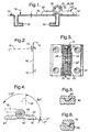
- Fig. 1 is a screw hinge 10 for one vertically or horizontally on one Frame or a wall 12 door or pivotally arranged about an axis 14
- Detect flap 16 in at least one swivel angle position for example is releasably held in one of the positions shown in FIG. 4.
- the Screw-on hinge 10 consists of a first one, for example on the frame or on the wall 12 attachable hinge part 18, the attachment for example could be done by means of two axially offset countersunk screws 20, see corresponding countersunk holes 22 in Figs. 3 and 4. Corresponding Holes can be found in a second, e.g. B. on the door or flap 16 screw-on hinge part 24. Both hinge parts 18, 24 each have one Bore 26, 28, see FIGS. 7 and 9, into which a hinge pin device 30 is recordable.
- the conditions can be seen again in a reduced representation, the solid line the closed door or flap can be seen within the wall or frame 12, and dashed at 90 ° pivots to show another position, which can be a releasably held position like.
- 2 may be a machine cover 12, and that Hinge 10 hold a flap 16 which can be pivoted about a horizontal axis is opened in the dashed representation in the horizontal direction and for example, access to the engine room allowed for maintenance purposes.
- FIG. 1 may represent a door 16 that is about a vertical axis 14 can be opened and closed, with sealing strips 32 are indicated, which are placed on edges of the frame or wall 12 and when the door 16 is closed, a tight one together with folds in the door Allow closure of the openings closed by the door 16.
- the sleeve part 34 has at its lower end 36 in FIG. 11 an axially aligned, radially projecting ledge or spring 38, which in a corresponding groove 40 can be received, which is in the area of the first hinge part 18 Hinge pin bore 26 formed in the area of the fastening tab 42 returns.
- this tongue and groove connection serves the sleeve 34 each in the bore 26 of the two ends of the To keep hinge part 18 rigid, but axially displaceable.
- the other end 44 has an annular end face in which four depressions offset by 90 ° 46 are arranged.
- the sleeve 34 forms an axial bore 48 which is close to the End 44 narrowed to a bore 50 of smaller diameter.
- a larger compression spring 52 can be accommodated, which is shown in FIG. 14 is shown and on the shoulder 54 formed by the narrowing to the bore 50 can support.
- the narrower bore 50 in turn allows one in FIG. 15 Pass screw bolt 56 shown, as in the following is described.
- the upper end of the sleeve 34 with the end surface having the depressions 46 is receivable in a bore 28, which is in Fig. 9 with respect to the second hinge part 24 is shown.
- This hole also forms a first hole area larger diameter, the sleeve 34 rotatably and axially displaceably and a second bore region 60 forming an annular shoulder 58 smaller diameter, the diameter of which is sufficient to turn the shaft to be able to pass through the bolt 56.
- the annular shoulder 58 carries according to Fig. 10, a bottom view of the part of FIG.
- the first hinge part 18 is designed so that it with its two Legs 66 engages around the inner part 68 of the second hinge part 24, whereby after corresponding bores 26 of the two legs 66 of the first Hinge part 18 to the two existing, to the hinge part center 67th symmetrically arranged bores 28 of the second hinge part 24 are aligned.
- This position can be from the outside in the bores 26 of the first hinge part 18th each a sleeve part 34 with its side 44 having the narrower bore 50 be inserted ahead until this side 44 in the bore 28 of the second Hinge part 24 has penetrated and fills, with component 34 at the same time its spring part 38 is aligned so that this spring 38 moves into the groove 40.
- This assembled position can be seen in Fig. 3.
- the length of the cap screw 56 is expediently chosen so that it disappears within the hinge parts.
- the hinge gets one aesthetic appearance, since the built-in locking device is not visible.
- a hinge according to FIG. 4 is such trained that it shows locking points at -5 °, at 85 ° and at 175 °.
- the frame or wall pushes the door into position 0 °, whereby Contact pressure arises.
- the door stays in the open position, the door leaf projecting substantially perpendicularly from the fastening surface.
- the hinge shown here this large opening angle allows (see the dashed line in Fig. 4), since it is a 180 ° hinge is.
- the cylinder screw 56 compressing the springs 52 enables through Tightening or loosening the nut 72 an adjustment of the pressure force and thus the Adjustment strength. You can do without this adjustability, instead of Cylinder screw 56 also a rivet of suitable length and diameter use, for example in the form of a hollow rivet, one of which is the rivet head Function of the screw head and its other rivet head that of the nut of the Cylinder screw takes over.
- the hinge parts can be injection molded from metal or preferably from plastic.
- the locking surfaces, if made of plastic, result in low coefficients of friction. For higher ones Resilience can also be favorable, the locking surfaces from a metal part form, which is inserted or injected into the plastic.
- the hinge pin device it is also possible to make the hinge pin device out of two nested ones Build up sleeves, the outer, first sleeve being fixed to the one hinge part is connected (such as pressed, glued), so that this sleeve with respect to the Hinge is not axially displaceable in the assembled state.
- the inner second sleeve is axially displaceable and rotatable.
- the one outer sleeve may then protrude radially inwards Ring shoulder which form a locking surface, while the other, inner sleeve the one on it forms a rotating, corresponding second locking surface, this sleeve in suitably rigid, but axially displaceable with the other hinge part connected is.
- the inner sleeve then contains the spring, which is the locking surfaces of the press the two sleeves together.
- the spring is penetrated by a retaining bolt or holding rivet, the latter possibly also in the form of a sleeve.
- This arrangement is special stable and enables a hinge with hinge flaps made of plastic, into which the e.g. sleeves made of metal are embedded, of particularly great strength.
- the invention can be evaluated commercially in control cabinet construction.
Claims (19)
- Charnière à visser (10) pour une porte ou un clapet (16) disposé de manière à pouvoir pivoter verticalement ou horizontalement sur un cadre ou une paroi (12), la porte ou le clapet (16) étant maintenu de manière amovible dans au moins une position d'angle de rotation (-5°, +85°C, +175°), constituée d'une première pièce (18) de charnière pouvant par exemple être fixée sur le cadre et d'une deuxième pièce (24) de charnière pouvant par exemple être fixée sur la porte ou le clapet (16), lesdites pièces (18, 24) de charnière étant à chaque fois symétriques autour de leur médiane (67) et présentant à chaque fois un trou (26, 28) destiné à recevoir un dispositif (30) de charnière à goupille, le dispositif de charnière à goupille comprenant au moins un manchon (34) qui est relié avec l'une pièce (18) de charnière de manière à ne pas pouvoir tourner et un dispositif de verrouillage à ressort étant disposé entre ledit manchon (34) et l'autre pièce (24) de charnière, caractérisée en ce que le dispositif (30) de charnière à goupille est en deux parties et en ce que l'une extrémité (44) de l'une pièce de charnière, qui se tourne vers l'autre pièce de charnière, forme le dispositif de verrouillage, et en ce que le dispositif de verrouillage est à chaque fois formé par une face avant de manchon et comprend à chaque fois un ressort (52) de compression à spirale disposé axialement à l'intérieur du manchon (52).
- Charnière à visser selon la revendication 1, caractérisée en ce que le dispositif de verrouillage présente un épaulement ou surface de fond de trou borgne (58) formé ou disposé dans la pièce de charnière (24) à l'extrémité de chaque trou (28) pour chaque goupille (30) de charnière, dans lequel on a prévu des creux ou des élévations (partie en recul ou en saillie) (46, 62), auxquels sont associés des élévations ou des creux (62, 46) de la face avant (46) du manchon et en ce que le ressort (52) pousse le manchon (34) avec ses élévations ou ses creux contre l'épaulement ou la surface de fond avec ses élévations ou ses creux.
- Charnière à visser selon la revendication 1 ou 2 caractérisée en ce que le raccord ne pouvant tourner entre l'une pièce (par exemple 18) de charnière et la goupille (par exemple 34) de charnière est obtenu par un dispositif (38, 40) à rainure et ressort ou par une forme de section prismatique ou non circulaire.
- Charnière à visser selon l'une quelconque des revendications 1 à 3, caractérisée en ce qu'une pièce (par exemple 18) de charnière entoure l'autre pièce (par exemple 24) de charnière sous forme d'une fourche.
- Charnière à visser selon l'une quelconque des revendications 1 à 4, caractérisée en ce que les deux extrémités (40) se faisant face des pièces (34) de charnière sont pourvues de parties en saillie ou en recul (62, 46) qui s'agrippent dans des parties en recul/en saillie correspondantes (46, 62) qui sont formées par des épaulements annulaires (58) dans le trou partiel de charnière dans lequel sont placées les extrémités (44) correspondantes.
- Charnière à visser selon la revendication 5, caractérisée en ce qu'à chaque fois l'autre extrémité (36) de la goupille (34) de charnière est placée dans le trou (26) de la goupille de charnière de l'autre pièce (18) de charnière de manière à ne pas pouvoir tourner mais de manière à pouvoir glisser axialement.
- Charnière à visser selon l'une quelconque des revendications 1 à 6, caractérisée en ce que le ressort est en deux parties et est constitué de deux ressorts de compression (52).
- Charnière à visser selon l'une quelconque des revendications 1 à 7, caractérisée en ce que les deux extrémités de ressort s'écartant l'une de l'autre du ou des ressorts de compression (52) sont comprimées par une vis (56) pénétrant dans les parties du ressort, un ressort s'appuyant sur la tête (70) de la vis et l'autre ressort s'appuyant sur un écrou (72) qui y est vissé.
- Charnière à visser selon l'une quelconque des revendications 1 à 8, caractérisé en ce que la face avant (44) du manchon présente quatre parties en saillie/en recul (62, 46) qui sont à une distance angulaire l'une de l'autre de 90 degrés.
- Charnière à visser selon l'une quelconque des revendications 1 à 9, caractérisée en ce qu'on a également prévu quatre parties en recul/en saillie (46, 62) formées par les épaulements (58) et qu'elles présentent une distance angulaire de 90° l'une par rapport à l'autre, l'orientation de 0° des parties en recul/en saillie présentant par rapport à la surface de fixation de la charnière (12) un décalage de quelques degrés, par exemple de 5°.
- Charnière à visser selon la revendication 10, caractérisée en ce que l'orientation des endroits de verrouillage est réalisée de telle manière que dans la position de fermeture de la porte ou du clapet, cette position de verrouillage est atteinte.
- Charnière à visser selon la revendication 10, caractérisée en ce que le dispositif de verrouillage est exécuté de telle manière que la pression de ressort des ressorts à spirale dans un angle de rotation autour du point de verrouillage conduit à un moment de rotation dans le sens du point de verrouillage et en ce que l'orientation d'un point de verrouillage pour la position de fermeture est conçue de telle manière que lorsque la porte ou le clapet est fermé, un moment de rotation agissant dans le sens de la fermeture s'établit sur cette porte ou clapet.
- Charnière à visser selon l'une quelconque des revendications 1 à 12, caractérisée en ce que les parties de charnière (18, 24) sont réalisées de telle manière qu'elles peuvent être vissées sur des surfaces de fixations (12, 16) affleurantes du cadre et de la porte ou du clapet.
- Charnière à visser selon l'une quelconque des revendications 8 à 13, caractérisée en ce que qu'un rivet, par exemple un rivet tubulaire, comprime les ressorts à compression, au lieu du boulon à visser.
- Charnière à visser selon l'une quelconque des revendications 1 à 14, caractérisée en ce que les pièces (18, 24) de charnière sont moulées par injection en matériau synthétique.
- Charnière à visser selon la revendication 15, caractérisée en ce que la surface de verrouillage (58, 60) de l'une pièce (24) de charnière est formée par une pièce métallique qui est incorporée, en particulier incorporée par moulage par injection, dans le matériau synthétique.
- Charnière à visser selon l'une quelconque des revendications 1 à 16, caractérisée en ce que le dispositif de charnière à goupille est formé par un premier manchon raccordé de manière fixe avec l'une pièce de charnière et un deuxième manchon raccordé de manière à ne pas pouvoir tourner, mais à pouvoir être déplacé axialement avec l'autre pièce de charnière, le deuxième manchon étant disposé dans le premier manchon et le premier manchon formant un épaulement annulaire radialement en saillie vers l'intérieur avec des dispositifs de verrouillage, sur lequel se place la face avant du deuxième manchon avec un dispositif de verrouillage analogue sous l'effet d'une force de ressort, ladite force de ressort étant obtenue par un ressort de compression à spirale disposé dans le deuxième manchon.
- Charnière à visser selon la revendication 17, caractérisée en ce que les deux manchons sont constitués de matériaux différents, tels qu'un métal et un matériau synthétique.
- Charnière à visser selon la revendication 17 ou 18, caractérisé en ce que le ou les ressort de compression à spirale sont maintenus sous tension par un boulon à visser ou un rivet, en particulier un rivet tubulaire, qui traverse le ou les ressorts à spirale.
Applications Claiming Priority (3)
| Application Number | Priority Date | Filing Date | Title |
|---|---|---|---|
| DE29815747U | 1998-09-02 | ||
| DE29815747U DE29815747U1 (de) | 1998-09-02 | 1998-09-02 | Anschraubscharnier mit Raststellung |
| PCT/EP1999/006023 WO2000014371A1 (fr) | 1998-09-02 | 1999-08-17 | Charniere a visser comportant une position d'arret |
Publications (2)
| Publication Number | Publication Date |
|---|---|
| EP1109983A1 EP1109983A1 (fr) | 2001-06-27 |
| EP1109983B1 true EP1109983B1 (fr) | 2002-10-23 |
Family
ID=8062112
Family Applications (1)
| Application Number | Title | Priority Date | Filing Date |
|---|---|---|---|
| EP99941634A Expired - Lifetime EP1109983B1 (fr) | 1998-09-02 | 1999-08-17 | Charniere a visser comportant une position d'arret |
Country Status (4)
| Country | Link |
|---|---|
| US (1) | US6568032B1 (fr) |
| EP (1) | EP1109983B1 (fr) |
| DE (3) | DE29815747U1 (fr) |
| WO (1) | WO2000014371A1 (fr) |
Families Citing this family (15)
| Publication number | Priority date | Publication date | Assignee | Title |
|---|---|---|---|---|
| US7062817B2 (en) * | 2003-03-14 | 2006-06-20 | Winia Mando, Inc. | Hinge assembly structure for opening and closing of door of storage facility |
| US6708536B1 (en) * | 2003-03-25 | 2004-03-23 | Chia Yu Yu | Anti-theft device for vehicles |
| PL1711672T3 (pl) * | 2004-01-26 | 2008-06-30 | Dieter Ramsauer | Zawias do montażu w wycięciach |
| US6986188B2 (en) * | 2004-06-14 | 2006-01-17 | Shin Zu Shing Co., Ltd. | Hinge |
| US7275285B1 (en) * | 2004-11-15 | 2007-10-02 | Lockheed Martin Corporation | Deployment hinge |
| CN201187522Y (zh) * | 2008-03-10 | 2009-01-28 | 深圳富泰宏精密工业有限公司 | 铰链结构及应用该铰链结构的便携式电子装置 |
| NL2005520C2 (nl) * | 2010-10-14 | 2011-09-13 | Estem B V | Scharnier voor een paneeldeur, in het bijzonder voor een koelmeubel. |
| GB201114861D0 (en) * | 2011-08-29 | 2011-10-12 | Bedi Parkarman S | PSB-Hinge |
| US8556330B2 (en) * | 2012-01-13 | 2013-10-15 | Chrysler Group Llc | Removable door with hinge detent |
| US9776595B2 (en) * | 2015-06-10 | 2017-10-03 | Ford Global Technologies, Llc | Soft close safety belt tongue/latch plate stowage compartment |
| EP3257490A1 (fr) | 2016-06-17 | 2017-12-20 | Sunrise Medical GmbH | Support latéral pour un siège de soutien postural |
| CN109025582A (zh) * | 2018-09-25 | 2018-12-18 | 张卫 | 自锁式限位合页 |
| CN110566072A (zh) * | 2019-09-09 | 2019-12-13 | 兴化市广福金属制品有限公司 | 一种改进型便组装不锈钢合页 |
| US11746581B2 (en) * | 2021-10-04 | 2023-09-05 | GM Global Technology Operations LLC | Flip hinge |
| CN113982396B (zh) * | 2021-11-02 | 2023-06-02 | 浙江王力安防产品有限公司 | 一种铰链铰接结构 |
Family Cites Families (24)
| Publication number | Priority date | Publication date | Assignee | Title |
|---|---|---|---|---|
| US294746A (en) * | 1884-03-04 | Thomas p | ||
| US769035A (en) * | 1903-11-23 | 1904-08-30 | Harrison B Walter | Lock-hinge. |
| US975097A (en) * | 1910-03-26 | 1910-11-08 | Joseph Wright | Hinge. |
| US1078002A (en) * | 1911-09-18 | 1913-11-11 | Frederick Schrey | Hinge. |
| US1440713A (en) * | 1922-03-14 | 1923-01-02 | Merritt W Ausbourne | Self-locking hinge |
| US1465912A (en) * | 1922-07-19 | 1923-08-21 | Jensen Martin | Hinge |
| US1946837A (en) * | 1932-10-13 | 1934-02-13 | Clayton Walter | Doorcheck |
| US2097651A (en) * | 1936-12-07 | 1937-11-02 | Myer C Cohen | Ratchet hinge |
| US2182546A (en) * | 1938-08-05 | 1939-12-05 | Thomas E Raymond | Hinge |
| DE2235555A1 (de) * | 1972-07-20 | 1974-01-31 | Daimler Benz Ag | Scharnier mit arretierung, insbesondere fuer kraftfahrzeugtueren |
| GB1391215A (en) * | 1972-08-24 | 1975-04-16 | Ihw Eng Ltd | Door hinge |
| DE2418147A1 (de) * | 1974-04-13 | 1975-11-06 | Volkswagenwerk Ag | Scharnier, insbesondere fuer eine kraftfahrzeugtuer |
| CH625591A5 (en) * | 1978-10-17 | 1981-09-30 | Corthesy Gerald Orraco | Hinge |
| NO154582C (no) | 1978-10-20 | 1986-11-05 | Ferrosan Ab | Analogifremgangsmaate for fremstilling av terapeutisk aktive difenyl-dibutylpiperazinkarboksamider. |
| AT376004B (de) * | 1980-07-11 | 1984-10-10 | Grass Alfred Metallwaren | Scharnier mit einer zuhalte- und offenhaltevorrichtung fuer tueren u.dgl. |
| DE3624649A1 (de) * | 1986-07-22 | 1988-02-18 | Lunke & Sohn Gmbh | Tuerscharnier fuer ein kraftfahrzeug mit einem tuerfeststeller |
| DE8627459U1 (fr) * | 1986-10-15 | 1987-11-19 | Lunke & Sohn Gmbh, 5810 Witten, De | |
| DE3905351A1 (de) * | 1989-02-22 | 1990-08-23 | Hueppe Gmbh & Co | Fluegeltuer, insbesondere in einer duschabtrennung |
| JP2534114Y2 (ja) * | 1991-09-30 | 1997-04-30 | 日本電気株式会社 | 折畳型電子機器の構造 |
| CA2062630C (fr) | 1992-01-13 | 1995-06-13 | Allen Riblett | Charniere a cliquet |
| DE19619473A1 (de) * | 1996-05-14 | 1997-11-20 | Scharwaechter Gmbh Co Kg | Mit einem aushängbaren Türscharnier baulich vereinigter Türfeststeller |
| US5715576A (en) * | 1997-02-04 | 1998-02-10 | Liu; Tai-Sheng | Hinge device for coupling two rotatable members |
| US5774938A (en) * | 1997-02-19 | 1998-07-07 | Erma W. Kent | Locking device for locking a closure in an open position |
| DE29709777U1 (de) * | 1997-06-05 | 1997-09-18 | Breust Volker Dipl Designer | Scharnier für Ganzglasduschen |
-
1998
- 1998-09-02 DE DE29815747U patent/DE29815747U1/de not_active Expired - Lifetime
-
1999
- 1999-08-17 DE DE19981699T patent/DE19981699D2/de not_active Expired - Fee Related
- 1999-08-17 DE DE59903199T patent/DE59903199D1/de not_active Expired - Lifetime
- 1999-08-17 US US09/786,221 patent/US6568032B1/en not_active Expired - Fee Related
- 1999-08-17 WO PCT/EP1999/006023 patent/WO2000014371A1/fr active IP Right Grant
- 1999-08-17 EP EP99941634A patent/EP1109983B1/fr not_active Expired - Lifetime
Also Published As
| Publication number | Publication date |
|---|---|
| DE29815747U1 (de) | 2000-01-05 |
| DE19981699D2 (de) | 2001-09-13 |
| DE59903199D1 (de) | 2002-11-28 |
| US6568032B1 (en) | 2003-05-27 |
| EP1109983A1 (fr) | 2001-06-27 |
| WO2000014371A1 (fr) | 2000-03-16 |
Similar Documents
| Publication | Publication Date | Title |
|---|---|---|
| EP1109983B1 (fr) | Charniere a visser comportant une position d'arret | |
| EP1711672B1 (fr) | Charniere a monter dans une ouverture | |
| DE4292446C1 (de) | Scharnier | |
| EP1153186B1 (fr) | Raccord permettant de connecter deux parois minces | |
| EP3612700A1 (fr) | Panneau de meuble comprenant une ferrure de battant et corps de meuble et meuble comprenant un tel panneau de meuble | |
| DE19728641A1 (de) | Positionsscharnier für Türen | |
| EP1849937A2 (fr) | Fixation par clip pour le montage de dispositifs d'armatures, comme fermeture, parties de charnière, poignée dans des percées d'une paroi mince | |
| DE2049743B2 (de) | Tuerverschluss | |
| EP0551872A2 (fr) | Porte avec une serrure à pêne demi-tour et/ou pêne de sécurité et ferrure de poignée pour cette serrure | |
| WO1996010679A1 (fr) | Fermeture a barre | |
| DE3418138C2 (de) | Bandzapfenbüchse | |
| DE19642637C2 (de) | Türscharnier zur schwenkbaren Lagerung eines Türflügels an einem Türrahmen | |
| EP1375803B1 (fr) | Charnière de porte notamment pour véhicules automobile | |
| DE10152699B4 (de) | Möbelscharnier mit Öffnungsmechanik, insbesondere für Möbeltüren | |
| DE3412832C2 (fr) | ||
| DE102008034070A1 (de) | Schließzylinder mit federkraftunterstützter Zylinderkernrückstellung | |
| WO1998059138A1 (fr) | Charniere pour portes d'armoire metallique | |
| DE102005057766B3 (de) | Beschlag für Türen, Fenster oder dergleichen | |
| EP0861953A1 (fr) | Poignée de manoeuvre | |
| EP0662559B1 (fr) | Penture | |
| CH709360A2 (de) | Selbstschliessendes Rollentürband. | |
| DE3129851A1 (de) | Mehrteiliger moebelfuss aus kunststoff | |
| DE4103923C2 (fr) | ||
| DE3109553A1 (de) | Haltevorrichtung fuer eine schwenktuer | |
| DE7819147U1 (de) | Schliessvorrichtung fuer eine pendeltuer |
Legal Events
| Date | Code | Title | Description |
|---|---|---|---|
| PUAI | Public reference made under article 153(3) epc to a published international application that has entered the european phase |
Free format text: ORIGINAL CODE: 0009012 |
|
| 17P | Request for examination filed |
Effective date: 20010220 |
|
| AK | Designated contracting states |
Kind code of ref document: A1 Designated state(s): AT BE CH CY DE DK ES FI FR GB GR IE IT LI LU MC NL PT SE |
|
| GRAG | Despatch of communication of intention to grant |
Free format text: ORIGINAL CODE: EPIDOS AGRA |
|
| 17Q | First examination report despatched |
Effective date: 20011227 |
|
| GRAG | Despatch of communication of intention to grant |
Free format text: ORIGINAL CODE: EPIDOS AGRA |
|
| GRAH | Despatch of communication of intention to grant a patent |
Free format text: ORIGINAL CODE: EPIDOS IGRA |
|
| GRAH | Despatch of communication of intention to grant a patent |
Free format text: ORIGINAL CODE: EPIDOS IGRA |
|
| GRAA | (expected) grant |
Free format text: ORIGINAL CODE: 0009210 |
|
| AK | Designated contracting states |
Kind code of ref document: B1 Designated state(s): DE FR GB |
|
| REG | Reference to a national code |
Ref country code: GB Ref legal event code: FG4D Free format text: NOT ENGLISH |
|
| REG | Reference to a national code |
Ref country code: IE Ref legal event code: FG4D Free format text: GERMAN |
|
| REF | Corresponds to: |
Ref document number: 59903199 Country of ref document: DE Date of ref document: 20021128 |
|
| GBT | Gb: translation of ep patent filed (gb section 77(6)(a)/1977) |
Effective date: 20030106 |
|
| ET | Fr: translation filed | ||
| REG | Reference to a national code |
Ref country code: IE Ref legal event code: FD4D Ref document number: 1109983E Country of ref document: IE |
|
| PG25 | Lapsed in a contracting state [announced via postgrant information from national office to epo] |
Ref country code: GB Free format text: LAPSE BECAUSE OF NON-PAYMENT OF DUE FEES Effective date: 20030817 |
|
| PLBE | No opposition filed within time limit |
Free format text: ORIGINAL CODE: 0009261 |
|
| STAA | Information on the status of an ep patent application or granted ep patent |
Free format text: STATUS: NO OPPOSITION FILED WITHIN TIME LIMIT |
|
| 26N | No opposition filed |
Effective date: 20030724 |
|
| GBPC | Gb: european patent ceased through non-payment of renewal fee |
Effective date: 20030817 |
|
| PG25 | Lapsed in a contracting state [announced via postgrant information from national office to epo] |
Ref country code: FR Free format text: LAPSE BECAUSE OF NON-PAYMENT OF DUE FEES Effective date: 20040430 |
|
| REG | Reference to a national code |
Ref country code: FR Ref legal event code: ST |
|
| PGFP | Annual fee paid to national office [announced via postgrant information from national office to epo] |
Ref country code: DE Payment date: 20170811 Year of fee payment: 19 |
|
| REG | Reference to a national code |
Ref country code: DE Ref legal event code: R082 Ref document number: 59903199 Country of ref document: DE Representative=s name: COHAUSZ & FLORACK PATENT- UND RECHTSANWAELTE P, DE |
|
| REG | Reference to a national code |
Ref country code: DE Ref legal event code: R082 Ref document number: 59903199 Country of ref document: DE Representative=s name: COHAUSZ & FLORACK PATENT- UND RECHTSANWAELTE P, DE Ref country code: DE Ref legal event code: R081 Ref document number: 59903199 Country of ref document: DE Owner name: RAMSAUER, DIETER, DE Free format text: FORMER OWNER: RAMSAUER, DIETER, 42555 VELBERT, DE |
|
| REG | Reference to a national code |
Ref country code: DE Ref legal event code: R119 Ref document number: 59903199 Country of ref document: DE |
|
| PG25 | Lapsed in a contracting state [announced via postgrant information from national office to epo] |
Ref country code: DE Free format text: LAPSE BECAUSE OF NON-PAYMENT OF DUE FEES Effective date: 20190301 |