EP1109983B1 - Screw-on hinge with blocked position - Google Patents
Screw-on hinge with blocked position Download PDFInfo
- Publication number
- EP1109983B1 EP1109983B1 EP99941634A EP99941634A EP1109983B1 EP 1109983 B1 EP1109983 B1 EP 1109983B1 EP 99941634 A EP99941634 A EP 99941634A EP 99941634 A EP99941634 A EP 99941634A EP 1109983 B1 EP1109983 B1 EP 1109983B1
- Authority
- EP
- European Patent Office
- Prior art keywords
- hinge
- screw
- sleeve
- spring
- hinge part
- Prior art date
- Legal status (The legal status is an assumption and is not a legal conclusion. Google has not performed a legal analysis and makes no representation as to the accuracy of the status listed.)
- Expired - Lifetime
Links
- 230000006835 compression Effects 0.000 claims description 25
- 238000007906 compression Methods 0.000 claims description 25
- 239000002184 metal Substances 0.000 claims description 7
- 239000000463 material Substances 0.000 claims description 4
- 230000002349 favourable effect Effects 0.000 description 7
- 210000003128 head Anatomy 0.000 description 4
- 238000010276 construction Methods 0.000 description 2
- 238000002347 injection Methods 0.000 description 2
- 239000007924 injection Substances 0.000 description 2
- 238000004519 manufacturing process Methods 0.000 description 2
- 238000007789 sealing Methods 0.000 description 2
- 230000004308 accommodation Effects 0.000 description 1
- 230000000712 assembly Effects 0.000 description 1
- 238000000429 assembly Methods 0.000 description 1
- 238000005452 bending Methods 0.000 description 1
- 230000009286 beneficial effect Effects 0.000 description 1
- 239000000428 dust Substances 0.000 description 1
- 230000000694 effects Effects 0.000 description 1
- 238000012423 maintenance Methods 0.000 description 1
- 210000001331 nose Anatomy 0.000 description 1
- 230000000149 penetrating effect Effects 0.000 description 1
- 239000000243 solution Substances 0.000 description 1
Images

Classifications
-
- E—FIXED CONSTRUCTIONS
- E05—LOCKS; KEYS; WINDOW OR DOOR FITTINGS; SAFES
- E05D—HINGES OR SUSPENSION DEVICES FOR DOORS, WINDOWS OR WINGS
- E05D11/00—Additional features or accessories of hinges
- E05D11/10—Devices for preventing movement between relatively-movable hinge parts
- E05D11/1028—Devices for preventing movement between relatively-movable hinge parts for maintaining the hinge in two or more positions, e.g. intermediate or fully open
- E05D11/1078—Devices for preventing movement between relatively-movable hinge parts for maintaining the hinge in two or more positions, e.g. intermediate or fully open the maintaining means acting parallel to the pivot
-
- E—FIXED CONSTRUCTIONS
- E05—LOCKS; KEYS; WINDOW OR DOOR FITTINGS; SAFES
- E05D—HINGES OR SUSPENSION DEVICES FOR DOORS, WINDOWS OR WINGS
- E05D5/00—Construction of single parts, e.g. the parts for attachment
- E05D5/10—Pins, sockets or sleeves; Removable pins
-
- E—FIXED CONSTRUCTIONS
- E05—LOCKS; KEYS; WINDOW OR DOOR FITTINGS; SAFES
- E05D—HINGES OR SUSPENSION DEVICES FOR DOORS, WINDOWS OR WINGS
- E05D7/00—Hinges or pivots of special construction
- E05D7/10—Hinges or pivots of special construction to allow easy separation or connection of the parts at the hinge axis
- E05D7/1005—Hinges or pivots of special construction to allow easy separation or connection of the parts at the hinge axis by axially moving free pins, balls or sockets
-
- E—FIXED CONSTRUCTIONS
- E05—LOCKS; KEYS; WINDOW OR DOOR FITTINGS; SAFES
- E05Y—INDEXING SCHEME ASSOCIATED WITH SUBCLASSES E05D AND E05F, RELATING TO CONSTRUCTION ELEMENTS, ELECTRIC CONTROL, POWER SUPPLY, POWER SIGNAL OR TRANSMISSION, USER INTERFACES, MOUNTING OR COUPLING, DETAILS, ACCESSORIES, AUXILIARY OPERATIONS NOT OTHERWISE PROVIDED FOR, APPLICATION THEREOF
- E05Y2800/00—Details, accessories and auxiliary operations not otherwise provided for
- E05Y2800/26—Form or shape
-
- E—FIXED CONSTRUCTIONS
- E05—LOCKS; KEYS; WINDOW OR DOOR FITTINGS; SAFES
- E05Y—INDEXING SCHEME ASSOCIATED WITH SUBCLASSES E05D AND E05F, RELATING TO CONSTRUCTION ELEMENTS, ELECTRIC CONTROL, POWER SUPPLY, POWER SIGNAL OR TRANSMISSION, USER INTERFACES, MOUNTING OR COUPLING, DETAILS, ACCESSORIES, AUXILIARY OPERATIONS NOT OTHERWISE PROVIDED FOR, APPLICATION THEREOF
- E05Y2900/00—Application of doors, windows, wings or fittings thereof
- E05Y2900/10—Application of doors, windows, wings or fittings thereof for buildings or parts thereof
- E05Y2900/13—Type of wing
- E05Y2900/132—Doors
-
- E—FIXED CONSTRUCTIONS
- E05—LOCKS; KEYS; WINDOW OR DOOR FITTINGS; SAFES
- E05Y—INDEXING SCHEME ASSOCIATED WITH SUBCLASSES E05D AND E05F, RELATING TO CONSTRUCTION ELEMENTS, ELECTRIC CONTROL, POWER SUPPLY, POWER SIGNAL OR TRANSMISSION, USER INTERFACES, MOUNTING OR COUPLING, DETAILS, ACCESSORIES, AUXILIARY OPERATIONS NOT OTHERWISE PROVIDED FOR, APPLICATION THEREOF
- E05Y2900/00—Application of doors, windows, wings or fittings thereof
- E05Y2900/10—Application of doors, windows, wings or fittings thereof for buildings or parts thereof
- E05Y2900/13—Type of wing
- E05Y2900/146—Shutters
Definitions
- the invention relates to a screw-on hinge for a vertical or horizontal a frame or wall pivotably arranged door or flap, in which the Door or flap is detachably held in at least one swivel angle position, consisting of a first z. B. hinge part attachable to the frame, and a second z. B. hinge part attachable to the door or flap, which Hinge parts are symmetrical about their median bisector and one each Include hole for receiving a hinge pin assembly, the Hinge pin assembly comprises a sleeve which is rotationally rigid with the one hinge part is connected and between which sleeve and the other hinge part one resilient locking device is arranged.
- Hinge part provided radially aligned to the hinge axis bore spaces open at one end to the sleeve and pick up the ball there while the other end of the hole can be closed by a slide which is then supported by the compression spring.
- the disadvantage here is that a special Configuration of the at least one hinge part (hinge flap) is necessary, which special configuration for an increased overall height of the hinge part leads.
- DE 29 41 860 A1 which corresponds to the preamble of claim 1, is a hinge consisting of two hinge parts known in which the hinge pin is formed by a sleeve in which one Compression spring is arranged, which is provided with the end of the projections with the a hinge part torsionally rigid sleeve against one in the other Hinge part arranged, with radial notches insert presses to to obtain an elastic locking at certain angles of rotation.
- the disadvantage is that the two hinge parts are not axially fixable to each other and therefore the hinge only in connection with a second, opposite hinge Type can be used (p. 6, lines 16-21).
- DE 23 42 945 also describes a hinge for a motor vehicle door, the has a locking device.
- a coil compression spring 10 which by a second Coaxially arranged compression spring 9 can be reinforced with radial Depressions provided, with the one hinge part 3 rotationally rigidly connected Control plates against pins 11, 12 which are guided transversely through the hinge pin 6 pressed which hinge pin is torsionally rigid with the other hinge part 1 are connected.
- DE-OS 22 35 555 discloses hinge tapes for a hinge with locking Coaxial and arranged on the hinge pin (plate) springs (claim 2).
- the object of the invention is to avoid the above disadvantages and a Screw-on hinge to create the one mentioned has a simpler construction, is more compact in its outer shape, fewer individual parts includes, is largely symmetrical, and therefore easier to assemble, and that has a longer lifespan.
- the hinge pin device is in two parts and that one end of a hinge part facing the other hinge part, the Forms locking device, and that the locking device from a sleeve end face is formed and includes an axially disposed within the sleeve coil spring.
- the sleeve face also provides a contour surface is available which has a locking device with a relatively lower Surface pressure enables what reduces material wear and the Lifetime of the hinge increased.
- the locking device comprises one at the end the hole for the hinge pin formed or arranged in the hinge part Shoulder or blind hole bottom surface in which depressions or elevations are provided for elevations or depressions of the sleeve face correspond, the compression spring the sleeve with its elevations or Depressions against the shoulder or floor surface with their depressions and Elevations (recesses, protrusions) presses.
- the torsionally rigid Connection between the one hinge part and the hinge pin by a tongue and groove device is obtained, or alternatively by non-circular, for example prismatic cross-sectional shape of the cross-section of the hinge pin on the one hand and the hole in the hinge part in which this hinge pin is to be inserted, on the other hand.
- a particularly stable and nevertheless simple form of a hinge is one those in which the one hinge part the other hinge part fork-shaped encloses, as can also be seen in the prior art.
- the sleeve-shaped hinge pin is executed in two parts and one end of a hinge pin part, which End to the other hinge pin part, which carries the locking device.
- both hinge pin parts of the two-part hinge pin accordingly their ends are provided with locking projections or locking recesses, which in engaging corresponding recesses or protrusions from ring shoulders are formed in the hinge part bore in which the corresponding ends of the Hinge pin parts are included.
- the other end of the hinge pin parts can then in the hinge pin hole of the other hinge part torsionally rigid, but possibly sliding in the axial direction be included.
- the sliding recording ensures that it can dodge in the axial direction while engaging and disengaging.
- the spring device for the latching device also has two parts is executed, in particular the spring ends of a screw penetrating the spring parts can be held, whereby one spring on the head of the screw and the other spring on one on the Screw screwed nut could support.
- This has the great advantage that the force with which the locking devices exert the holding force, not from parts of the Hinge must be included and this additional hinge parts load, but by the screw, which otherwise has no holding function can be applied.
- the stability of the Overall arrangement greatly enlarged.
- the two forks of the fork-shaped hinge part relieved of bending forces.
- the depressions or noses (projections) formed by the shoulder should also be in this case four times and a distance of 90 degrees to have.
- the coordination of these lugs (projections) or depressions with each other leads to a particularly stable hinge shape and a particularly high one Holding force in the different locking positions.
- the latching device can also be designed such that the spring pressure of the coil spring within a small to the click point lying angle of rotation to a torque in the direction of the rest point leads, and that the orientation of a locking point for the closed position in such a way is taken that when the door or flap is closed, the rest point is not quite is reached and therefore there is a torque acting in the closing direction.
- the door is held in its closed position with a certain pressure so that there is no rattling or play movement, as might be the case, when the door is in the closed position exactly at the zero point of the rest position.
- hinge parts are designed in such a way that they open mutually aligned fastening surfaces of the frame on the one hand and the door or Flap are screwed on the other hand.
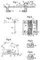
- Fig. 1 is a screw hinge 10 for one vertically or horizontally on one Frame or a wall 12 door or pivotally arranged about an axis 14
- Detect flap 16 in at least one swivel angle position for example is releasably held in one of the positions shown in FIG. 4.
- the Screw-on hinge 10 consists of a first one, for example on the frame or on the wall 12 attachable hinge part 18, the attachment for example could be done by means of two axially offset countersunk screws 20, see corresponding countersunk holes 22 in Figs. 3 and 4. Corresponding Holes can be found in a second, e.g. B. on the door or flap 16 screw-on hinge part 24. Both hinge parts 18, 24 each have one Bore 26, 28, see FIGS. 7 and 9, into which a hinge pin device 30 is recordable.
- the conditions can be seen again in a reduced representation, the solid line the closed door or flap can be seen within the wall or frame 12, and dashed at 90 ° pivots to show another position, which can be a releasably held position like.
- 2 may be a machine cover 12, and that Hinge 10 hold a flap 16 which can be pivoted about a horizontal axis is opened in the dashed representation in the horizontal direction and for example, access to the engine room allowed for maintenance purposes.
- FIG. 1 may represent a door 16 that is about a vertical axis 14 can be opened and closed, with sealing strips 32 are indicated, which are placed on edges of the frame or wall 12 and when the door 16 is closed, a tight one together with folds in the door Allow closure of the openings closed by the door 16.
- the sleeve part 34 has at its lower end 36 in FIG. 11 an axially aligned, radially projecting ledge or spring 38, which in a corresponding groove 40 can be received, which is in the area of the first hinge part 18 Hinge pin bore 26 formed in the area of the fastening tab 42 returns.
- this tongue and groove connection serves the sleeve 34 each in the bore 26 of the two ends of the To keep hinge part 18 rigid, but axially displaceable.
- the other end 44 has an annular end face in which four depressions offset by 90 ° 46 are arranged.
- the sleeve 34 forms an axial bore 48 which is close to the End 44 narrowed to a bore 50 of smaller diameter.
- a larger compression spring 52 can be accommodated, which is shown in FIG. 14 is shown and on the shoulder 54 formed by the narrowing to the bore 50 can support.
- the narrower bore 50 in turn allows one in FIG. 15 Pass screw bolt 56 shown, as in the following is described.
- the upper end of the sleeve 34 with the end surface having the depressions 46 is receivable in a bore 28, which is in Fig. 9 with respect to the second hinge part 24 is shown.
- This hole also forms a first hole area larger diameter, the sleeve 34 rotatably and axially displaceably and a second bore region 60 forming an annular shoulder 58 smaller diameter, the diameter of which is sufficient to turn the shaft to be able to pass through the bolt 56.
- the annular shoulder 58 carries according to Fig. 10, a bottom view of the part of FIG.
- the first hinge part 18 is designed so that it with its two Legs 66 engages around the inner part 68 of the second hinge part 24, whereby after corresponding bores 26 of the two legs 66 of the first Hinge part 18 to the two existing, to the hinge part center 67th symmetrically arranged bores 28 of the second hinge part 24 are aligned.
- This position can be from the outside in the bores 26 of the first hinge part 18th each a sleeve part 34 with its side 44 having the narrower bore 50 be inserted ahead until this side 44 in the bore 28 of the second Hinge part 24 has penetrated and fills, with component 34 at the same time its spring part 38 is aligned so that this spring 38 moves into the groove 40.
- This assembled position can be seen in Fig. 3.
- the length of the cap screw 56 is expediently chosen so that it disappears within the hinge parts.
- the hinge gets one aesthetic appearance, since the built-in locking device is not visible.
- a hinge according to FIG. 4 is such trained that it shows locking points at -5 °, at 85 ° and at 175 °.
- the frame or wall pushes the door into position 0 °, whereby Contact pressure arises.
- the door stays in the open position, the door leaf projecting substantially perpendicularly from the fastening surface.
- the hinge shown here this large opening angle allows (see the dashed line in Fig. 4), since it is a 180 ° hinge is.
- the cylinder screw 56 compressing the springs 52 enables through Tightening or loosening the nut 72 an adjustment of the pressure force and thus the Adjustment strength. You can do without this adjustability, instead of Cylinder screw 56 also a rivet of suitable length and diameter use, for example in the form of a hollow rivet, one of which is the rivet head Function of the screw head and its other rivet head that of the nut of the Cylinder screw takes over.
- the hinge parts can be injection molded from metal or preferably from plastic.
- the locking surfaces, if made of plastic, result in low coefficients of friction. For higher ones Resilience can also be favorable, the locking surfaces from a metal part form, which is inserted or injected into the plastic.
- the hinge pin device it is also possible to make the hinge pin device out of two nested ones Build up sleeves, the outer, first sleeve being fixed to the one hinge part is connected (such as pressed, glued), so that this sleeve with respect to the Hinge is not axially displaceable in the assembled state.
- the inner second sleeve is axially displaceable and rotatable.
- the one outer sleeve may then protrude radially inwards Ring shoulder which form a locking surface, while the other, inner sleeve the one on it forms a rotating, corresponding second locking surface, this sleeve in suitably rigid, but axially displaceable with the other hinge part connected is.
- the inner sleeve then contains the spring, which is the locking surfaces of the press the two sleeves together.
- the spring is penetrated by a retaining bolt or holding rivet, the latter possibly also in the form of a sleeve.
- This arrangement is special stable and enables a hinge with hinge flaps made of plastic, into which the e.g. sleeves made of metal are embedded, of particularly great strength.
- the invention can be evaluated commercially in control cabinet construction.
Landscapes
- Engineering & Computer Science (AREA)
- Mechanical Engineering (AREA)
- Closing And Opening Devices For Wings, And Checks For Wings (AREA)
- Hinges (AREA)
Description
Die Erfindung betrifft ein Anschraubscharnier für eine vertikal oder horizontal an einem Rahmen oder Wand schwenkbar angeordnete Tür oder Klappe, bei dem die Tür oder Klappe in zumindest einer Schwenkwinkelstellung lösbar gehalten ist, bestehend aus einem ersten z. B. am Rahmen befestigbaren Scharnierteil, und einem zweiten z. B. an der Tür oder Klappe befestigbaren Scharnierteil, welche Scharnierteile jeweils um ihre Mittelhalbierende symmetrisch sind und jeweils eine Bohrung zur Aufnahme einer Scharnierstiftanordnung umfassen, wobei die Scharnierstiftanordnung eine Hülse umfaßt, die mit dem einen Schamierteil drehstarr verbunden ist und zwischen welcher Hülse und dem anderen Scharnierteil eine federnde Rasteinrichtung angeordnet ist.The invention relates to a screw-on hinge for a vertical or horizontal a frame or wall pivotably arranged door or flap, in which the Door or flap is detachably held in at least one swivel angle position, consisting of a first z. B. hinge part attachable to the frame, and a second z. B. hinge part attachable to the door or flap, which Hinge parts are symmetrical about their median bisector and one each Include hole for receiving a hinge pin assembly, the Hinge pin assembly comprises a sleeve which is rotationally rigid with the one hinge part is connected and between which sleeve and the other hinge part one resilient locking device is arranged.
Ein derartiges Anschraubscharnier wird in der US 5 412 842 beschrieben. Durch das bekannte Scharnier ist es möglich, eine Tür an einer vorbestimmten Position relativ zum Rahmen lösbar zu halten, wenn die Tür zum Zwecke des Öffnens oder Schließens verschwenkt wird. Bei der bekannten Anordnung sind an der Hülse eingesenkte Radialbohrungen vorgesehen, in die federbelastete Kugeln einlaufen können. Mit dem Einlaufen der Kugel wird die Hülse und damit das mit dieser Hülse verbundene Scharnierteil (Scharnierlappen) und damit wiederum die Tür in der entsprechenden Stellung mit einer Kraft festgehalten, die von der Federspannung und dem Auflaufwinkel der Kugel abhängt. Um die Feder aufzunehmen, sind in dem einen Scharnierteil radial zur Schamierachse ausgerichtete Bohrungsräume vorgesehen, die sich mit ihrem einen Ende zur Hülse öffnen und dort die Kugel aufnehmen, während das andere Ende der Bohrung durch einen Schieber verschlossen werden kann, an dem sich dann die Druckfeder abstützt. Nachteilig ist hier, daß eine spezielle Ausgestaltung des zumindest einen Scharnierteils (Scharnierlappens) notwendig ist, welche spezielle Ausgestaltung zu einer vergrößerten Bauhöhe des Scharnierteils führt. Es ergeben sich auch relativ viele Bauteile, bei der in der Entgegenhaltung dargestellten Ausführungsform sind es insgesamt drei Kugeln, drei Druckfedern und eine einschiebbare Halteplatte, die notwendig sind, um das gewünschte Ergebnis zu erreichen. Schwierigkeiten gibt es auch bei der Montage, weil Kugeln, Druckfedern und Platte erst dann montiert werden können, wenn sich der hülsenförmige, mit den Einlaufdurchbrüchen für die Kugeln versehene Scharnierstift an Ort und Stelle innerhalb der beiden Scharnierteile befindet. Ein weiterer Nachteil der Kugel ist der punktförmige Druckpunkt, was zu hoher Flächenpressung und schnellem Materialverschleiß führt.Such a screw-on hinge is described in US Pat. No. 5,412,842. By the Known hinge, it is possible to relative a door at a predetermined position to hold detachable to the frame when the door is for opening or Closing is pivoted. In the known arrangement are on the sleeve countersunk radial holes are provided, into which spring-loaded balls enter can. With the arrival of the ball, the sleeve and thus the sleeve connected hinge part (hinge flap) and thus in turn the door in the corresponding position held with a force by the spring tension and depends on the run-up angle of the ball. To take up the spring are in one Hinge part provided radially aligned to the hinge axis bore spaces open at one end to the sleeve and pick up the ball there while the other end of the hole can be closed by a slide which is then supported by the compression spring. The disadvantage here is that a special Configuration of the at least one hinge part (hinge flap) is necessary, which special configuration for an increased overall height of the hinge part leads. There are also a relatively large number of components in the citation embodiment shown there are a total of three balls, three compression springs and a retractable holding plate, which are necessary to achieve the desired result to reach. There are also difficulties with assembly, because balls, compression springs and plate can only be installed when the sleeve-shaped, with the Inlet openings for the ball-mounted hinge pin in place located within the two hinge parts. Another disadvantage of the ball is that punctiform pressure point, resulting in high surface pressure and fast Material wear leads.
Aus der DE 29 41 860 A1, die dem Oberbegriff des Anspruchs 1 entspricht, ist ein aus zwei Scharnierteilen bestehendes Scharnier
bekannt, bei der der Scharnierstift von einer Hülse gebildet wird, in der eine
Druckfeder angeordnet ist, die das mit Vorsprüngen versehene Ende der mit dem
einen Scharnierteil drehstarr verbundenen Hülse gegen einen in dem anderen
Scharnierteil angeordneten, mit radialen Kerben versehenen Einsatz drückt, um an
bestimmten Drehwinkeln eine elastische Arretierung zu erhalten. Nachteilig ist, daß
die beiden Scharnierteile nicht zueinander axial fixierbar sind und daher das Scharnier
nur in Verbindung mit einem zweiten, gegenläufig ausgeführten Scharnier gleichen
Typs eingesetzt werden kann (S. 6, Z. 16 - 21).DE 29 41 860 A1, which corresponds to the preamble of
Aus der DE 24 18 147 ist ein Scharnier für eine Kraftahrzeugtür mit zwei durch einen Scharnierstift zentrierten, zusammenwirkende Sitzflächen tragenden Scharnierteilen bekannt. Zur Feststellung in einer Öffnungsstellung werden die mit Kerben bzw. Vorsprüngen ausgestatteten Sitzflächen durch das Türgewicht oder durch nicht näher erläuterte Federn (S. 2, Z. 14) aufeinandergepreßt. Das eine Scharnierteil umschließt gabelförmig das andere. DE 24 18 147 discloses a hinge for a motor vehicle door with two through one Hinge pin centered hinge parts carrying interacting seat surfaces known. To determine in an open position, those with notches or Projections equipped seats by the door weight or by not closer explained springs (p. 2, line 14) pressed together. That encloses a hinge part the other forked.
Die DE 23 42 945 beschreibt ebenfalls ein Scharnier für eine Kraftfahrtzeugtür, das
eine Arretiereinrichtung besitzt. Durch eine Spiraldruckfeder 10, die durch eine zweite
koaxial angeordnete Druckfeder 9 verstärkt werden kann, werden mit radialen
Einsenkungen versehene, mit dem einen Scharnierteil 3 drehstarr verbundene
Steuerplatten gegen durch den Scharnierbolzen 6 quer hindurchgeführte Stifte 11, 12
gepreßt, welche Scharnierbolzen drehstarr mit dem anderen Scharnierteil 1
verbunden sind.DE 23 42 945 also describes a hinge for a motor vehicle door, the
has a locking device. By a
Zwei gegeneinander gerichtete, durch eine Schraube gehaltene Tellerfederpakete zeigt das Scharnier der EP 0 266 490 B1, siehe Fig. 4, vorgesehen für eine arretierbare Fahrzeugtür.Two diaphragm spring assemblies facing each other and held by a screw shows the hinge of EP 0 266 490 B1, see Fig. 4, provided for a lockable vehicle door.
Die DE-OS 22 35 555 offenbart für ein Scharnier mit Arretierung Schamierbänder mit koaxial und auf dem Scharnierzapfen angeordneten (Teller-)Federn (Anspruch 2).DE-OS 22 35 555 discloses hinge tapes for a hinge with locking Coaxial and arranged on the hinge pin (plate) springs (claim 2).
Die DE 31 26 933 A1 beschäftigt sich mit einem Scharnierband für Türen, das Raststellungen ermöglicht. Durch Restschließdruck wird eine Zuhaltekraft bewirkt (S. 7, Z. 11).DE 31 26 933 A1 deals with a hinge for doors, the Rest positions possible. A locking force is exerted by the residual closing pressure (p. 7, line 11).
Die DE 36 24 649 A1 erwähnt einen Bolzen 4 mit Stauchung und offenbart damit das Niet-Prinzip für ein feststellbares Scharnier für Kraftfahrzeuge.DE 36 24 649 A1 mentions a bolt 4 with compression and thus discloses this Rivet principle for a lockable hinge for motor vehicles.
Die DE 39 05 351 A1 erläutert eine Flügeltür und dabei auch Scharniere mit Rasteinrichtung, wobei gemäß Sp. 2, Z. 49 - 51 Scharnierteile und Rastteile auch aus Kunststoff gespritzt sein können, ebenso wie es möglich ist, einen aus Metall bestehenden Lagerzapfen in Kunststoff einzuspritzen.DE 39 05 351 A1 explains a hinged door and also hinges Locking device, whereby according to column 2, lines 49-51 hinge parts and locking parts also made Plastic can be injection molded, as can one made of metal inject existing bearing journal into plastic.
Die DE 196 19 473 A1 erwähnt im Zusammenhang mit einem aushängbaren Türscharnier mit baulich vereinten Türfeststeller in Sp. 3, Z. 44 einen Kunststoffgleiter.DE 196 19 473 A1 mentions in connection with a detachable Door hinge with structurally combined door retainer in column 3, line 44 a plastic glider.
Die meisten der aus den obigen Druckschriften bekannten Scharniere lassen Kompaktheit vermissen, häufig sind auch die Federeinrichtungen sichtbar und wirken nicht nur unästhetisch, sondern stellen auch Staubfänger dar. Abgesehen von der eingangs genannten, als nächstliegenden Stand der Technik ausgewählten US 5 412 842 (sowie möglicherweise der DE 29 41 860 A1) beschreibt keine der Druckschriften ein für Blechschranktüren geeignetes Scharnier.Most of the hinges known from the above publications leave Miss compactness, the spring devices are often visible and effective not only unaesthetic, but also represent dust catchers. Apart from the US 5,412 mentioned at the beginning, selected as the closest prior art 842 (and possibly DE 29 41 860 A1) does not describe any of the publications a hinge suitable for sheet metal cabinet doors.
Aufgabe der Erfindung ist es, die obigen Nachteile zu vermeiden und ein Anschraubscharnier gemäß der eingangs genannten Art zu schaffen, das einen einfacheren Aufbau hat, kompakter in der äußeren Form ist, weniger Einzelteile umfaßt, weitgehend symmetrisch ist, und daher einfacher montiert werden kann, und das eine größere Lebensdauer besitzt.The object of the invention is to avoid the above disadvantages and a Screw-on hinge to create the one mentioned has a simpler construction, is more compact in its outer shape, fewer individual parts includes, is largely symmetrical, and therefore easier to assemble, and that has a longer lifespan.
Gelöst wird die Aufgabe dadurch, daß die Scharnierstifteinrichtung zweiteilig ist und daß das eine Ende des einen Scharnierteils, das zum anderen Scharnierteil weist, die Rasteinrichtung bildet, und daß die Rasteinrichtung von einer Hülsenstirnseite gebildet ist und eine axial innerhalb der Hülse angeordnete Spiraldruckfeder umfaßt.The object is achieved in that the hinge pin device is in two parts and that one end of a hinge part facing the other hinge part, the Forms locking device, and that the locking device from a sleeve end face is formed and includes an axially disposed within the sleeve coil spring.
Durch diese Merkmale wird es mögich, den Raum des Scharnierbolzens für die Rasteinrichtung heranzuziehen und es wird vermieden, daß dazu eines der anschraubbaren Schamierteile des Anschraubscharniers herangezogen werden muß, was die oben geschilderten Probleme verursacht. Die Hülsenstirnseite stellt zudem eine Konturfläche zur Verfügung, die eine Rasteinrichtung mit relativ niedriger Flächenpressung ermöglicht, was den Materialverschleiß reduziert und die Lebensdauer des Scharniers erhöht.These features make it possible to use the space of the hinge pin for the Use locking device and it is avoided that one of the screw-on hinge parts of the screw-on hinge must be used, which causes the problems outlined above. The sleeve face also provides a contour surface is available which has a locking device with a relatively lower Surface pressure enables what reduces material wear and the Lifetime of the hinge increased.
Die Symmetrie des Schamiers und seiner Teile erleichtert nicht nur die Montage, auch ein nachträgliches Ändern des Türanschlags wird erleichtert.The symmetry of the hinge and its parts not only makes assembly easier, too a subsequent change of the door stop is made easier.
Gemäß einer Weiterbildung der Erfindung umfaßt die Rasteinrichtung eine am Ende der Bohrung für den Scharnierstift im Scharnierteil gebildete oder angeordnete Schulter oder Sacklochbodenfläche, in der Einsenkungen oder Erhebungen vorgesehen sind, die zu Erhebungen oder Einsenkungen der Hülsenstirnseite korrespondieren, wobei die Druckfeder die Hülse mit ihren Erhebungen oder Einsenkungen gegen die Schulter oder Bodenfläche mit ihren Einsenkungen und Erhebungen (Rücksprüngen, Vorsprüngen) drückt. Dies stellt eine besonders einfache Maßnahme dar, um die gewünschten Raststellungen zu erlangen, ohne daß dafür verlierbare Kugeln eingesetzt werden, die zudem bei der Montage des Scharniers zu Umständlichkeiten führen.According to a development of the invention, the locking device comprises one at the end the hole for the hinge pin formed or arranged in the hinge part Shoulder or blind hole bottom surface in which depressions or elevations are provided for elevations or depressions of the sleeve face correspond, the compression spring the sleeve with its elevations or Depressions against the shoulder or floor surface with their depressions and Elevations (recesses, protrusions) presses. This represents a particularly simple one Measure to achieve the desired rest positions without it captive balls are used, which also when mounting the hinge too Fuss.
Es ist aus Gründen der vereinfachten Herstellung günstig, wenn die drehstarre Verbindung zwischen dem einen Scharnierteil und dem Scharnierstift durch eine Nut-Feder-Einrichtung erlangt wird, oder alternativ durch unrunde, beispielsweise prismatische Querschnittsform des Querschnitts des Scharnierstiftes einerseits und der Bohrung im Scharnierteil, in der dieser Scharnierstift eingesteckt werden soll, andererseits.For reasons of simplified production, it is favorable if the torsionally rigid Connection between the one hinge part and the hinge pin by a tongue and groove device is obtained, or alternatively by non-circular, for example prismatic cross-sectional shape of the cross-section of the hinge pin on the one hand and the hole in the hinge part in which this hinge pin is to be inserted, on the other hand.
Dem Scharnierstift die Form einer Hülse zu geben, hat nicht nur Materialeinsparungsvorteile, sondern erleichtert auch die Herstellung von Vorsprüngen und Rücksprüngen an der Stirnfläche dieses hülsenförmigen Schamierstiftes. Außerdem ergeben sich bei noch zu schildernden weiteren Ausführungsformen besondere Vorteile, wie Unterbringungsmöglichkeit einer Spiraldruckfeder und eines Schraubbolzens oder Niets.Giving the hinge pin the shape of a sleeve is not just about that Material saving advantages, but also facilitates the production of Projections and recesses on the end face of this sleeve-shaped Hinge pin. In addition, there are more to be described Embodiments special advantages, such as the possibility of accommodation Coil compression spring and a bolt or rivet.
Eine besonders stabile und gleichwohl einfache Form eines Scharniers ist eine solche, bei der das eine Scharnierteil das andere Scharnierteil gabelförmig umschließt, wie es auch beim Stand der Technik zu erkennen ist. Besonders bei dieser Form des Scharniers ist es günstig, daß der hülsenförmige Scharnierstift zweiteilig ausgeführt wird und das eine Ende des einen Scharnierstiftteils, welches Ende zum anderen Scharnierstiftteil weist, die Rasteinrichtung trägt. Zur Erhöhung der Rastkraft ist es günstig, wenn gemäß einer noch anderen Ausführungsform der Erfindung beide Scharnierstiftteile des zweiteiligen Scharnierstiftes entsprechend auf ihren Stirnenden mit Rastvorsprüngen oder Rastrücksprüngen versehen sind, die in entsprechenden Rücksprüngen bzw. Vorsprüngen eingreifen, die von Ringschultern in der Scharnierteilbohrung gebildet werden, in der die entsprechenden Enden der Scharnierstiftteile aufgenommen sind.A particularly stable and nevertheless simple form of a hinge is one those in which the one hinge part the other hinge part fork-shaped encloses, as can also be seen in the prior art. Especially at this form of hinge, it is favorable that the sleeve-shaped hinge pin is executed in two parts and one end of a hinge pin part, which End to the other hinge pin part, which carries the locking device. To increase the Latching force, it is favorable if according to yet another embodiment of the Invention on both hinge pin parts of the two-part hinge pin accordingly their ends are provided with locking projections or locking recesses, which in engaging corresponding recesses or protrusions from ring shoulders are formed in the hinge part bore in which the corresponding ends of the Hinge pin parts are included.
Das jeweils andere Ende der Schamierstiftteile kann dann in die Scharnierstiftbohrung des anderen Scharnierteils drehstarr, aber ggf. in axialer Richtung gleitend aufgenommen werden. Durch die gleitende Aufnahme ist gewährleistet, daß sie während des Ein- und Ausrastens in axialer Richtung ausweichen können.The other end of the hinge pin parts can then in the hinge pin hole of the other hinge part torsionally rigid, but possibly sliding in the axial direction be included. The sliding recording ensures that it can dodge in the axial direction while engaging and disengaging.
Es ist günstig, wenn auch die Federeinrichtung für die Rasteinrichtung zweiteilig ausgeführt wird, wobei insbesondere die voneinander weggerichteten Federenden von einer die Federteile durchdringenden Schraube gehalten werden können, wobei sich die eine Feder auf den Kopf der Schraube und die andere Feder auf eine auf die Schraube aufgeschraubte Mutter abstützen könnte. Dies hat den großen Vorteil, daß die Kraft, mit der die Rasteinrichtungen die Haltekraft ausüben, nicht von Teilen des Scharniers aufgenommen werden müssen und dadurch diese Scharnierteile zusätzlich belasten, sondern durch die sonst keine Haltefunktion ausübende Schraube aufgebracht werden kann. Durch diese Maßnahme wird also die Stabilität der Gesamtanordnung stark vergrößert. Gleichzeitig werden die beiden Gabelzinken des gabelförmigen Scharnierteils von Aufbiegekräften entlastet.It is favorable if the spring device for the latching device also has two parts is executed, in particular the spring ends of a screw penetrating the spring parts can be held, whereby one spring on the head of the screw and the other spring on one on the Screw screwed nut could support. This has the great advantage that the force with which the locking devices exert the holding force, not from parts of the Hinge must be included and this additional hinge parts load, but by the screw, which otherwise has no holding function can be applied. By this measure, the stability of the Overall arrangement greatly enlarged. At the same time the two forks of the fork-shaped hinge part relieved of bending forces.
Es hat sich als günstig erwiesen, wenn die Stirnfläche der Hülse vier Nasen (oder Erhebungen) bzw. Einsenkungen aufweist, die voneinander einen Abstand von jeweils 90 Winkelgraden haben. Dadurch ergeben sich besonders günstige Verhältnisse für Scharniere, die einen Öffnungswinkel von 180° ermöglichen. Bei dieser Anordnung ist nämlich eine Funktion möglich, bei der sowohl in der Schließposition, wie auch in der um 180° geöffneten Position wie auch bei halben Öffnungswinkel von 90° eine Arretierung sich ergibt. Außerdem ist dies ein günstiger Kompromiß zwischen Anzahl der Rastnasen einerseits und der Breite der Nasen (Vorsprünge) andererseits, was zu einem günstigen Kompromiß zwischen Stabilität einerseits und Haltekraft andererseits führt.It has proven advantageous if the end face of the sleeve has four lugs (or Elevations) or depressions, the distance from each other Have 90 degrees. This results in particularly favorable conditions for Hinges that allow an opening angle of 180 °. With this arrangement namely a function possible in which both in the closed position, as in the 180 ° open position as well as a half opening angle of 90 ° Locking arises. It is also a good compromise between numbers the locking lugs on the one hand and the width of the lugs (protrusions) on the other hand what to a favorable compromise between stability on the one hand and holding power on the other leads.
Auch die von der Schulter gebildeten Einsenkungen oder Nasen (Vorsprünge) sollten in diesem Fall vierfach vorgesehen sein und einen Abstand von 90 Winkelgraden haben. Die Abstimmung dieser Nasen (Vorsprünge) bzw. Einsenkungen aufeinander führt zu einer besonders stabilen Scharnierform, und zu einer besonders hohen Haltekraft in den verschiedenen Raststellungen.The depressions or noses (projections) formed by the shoulder should also be in this case four times and a distance of 90 degrees to have. The coordination of these lugs (projections) or depressions with each other leads to a particularly stable hinge shape and a particularly high one Holding force in the different locking positions.
Meist wird es günstig sein, die Ausrichtung der Raststellen derart zu treffen, daß eine Raststellung bei Erreichen der Schließstellung der Tür oder Klappe gerade ebenfalls erreicht ist. Alternativ kann aber die Rasteinrichtung auch so ausgestaltet sein, daß der Federdruck der Spiralfeder innerhalb eines kleinen, um den Rastpunkt herumliegenden Drehwinkels zu einem Drehmoment in Richtung des Rastpunktes führt, und daß die Ausrichtung des einen Rastpunktes für die Schließstellung derart getroffen ist, daß bei geschlossener Tür oder Klappe der Rastpunkt noch nicht ganz erreicht ist und daher ein in Schließrichtung wirkendes Drehmoment vorhanden ist. Das führt dazu, daß die Tür mit einem gewissen Druck in ihre Schließstellung gehalten wird, so daß keine Klapper- oder Spielbewegung auftritt, wie es der Fall sein könnte, wenn sich die Tür in Schließstellung genau im Nullpunkt der Raststellung befindet.It will usually be beneficial to align the rest stops in such a way that a Lock position when the door or flap is in the closed position is reached. Alternatively, however, the latching device can also be designed such that the spring pressure of the coil spring within a small to the click point lying angle of rotation to a torque in the direction of the rest point leads, and that the orientation of a locking point for the closed position in such a way is taken that when the door or flap is closed, the rest point is not quite is reached and therefore there is a torque acting in the closing direction. As a result, the door is held in its closed position with a certain pressure so that there is no rattling or play movement, as might be the case, when the door is in the closed position exactly at the zero point of the rest position.
Meist wird es günstig sein, wenn die Scharnierteile derart gestaltet sind, daß sie auf zueinander fluchtenden Befestigungsflächen von Rahmen einerseits und Tür oder Klappe andererseits aufschraubbar sind.It will usually be convenient if the hinge parts are designed in such a way that they open mutually aligned fastening surfaces of the frame on the one hand and the door or Flap are screwed on the other hand.
Die Erfindung wird nachstehend anhand von Ausführungsbeispielen näher erläutert, die in den Zeichnungen dargestellt sind.The invention is explained in more detail below on the basis of exemplary embodiments, which are shown in the drawings.
Es zeigt:
in einer Querschnittsansicht eine dünne Wand mit einer durch eine Klappe verschließbaren Öffnung, welche Klappe durch ein erfindungsgemäß ausgestaltetes Scharnier an der dünnen Wand gehalten wird;
in verkleinerter Darstellung die in Fig. 1 dargestellte Klappe in um 90° geöffneter, in dieser Stellung arretierter Haltestellung;
eine Draufsicht auf das Scharnier mit geschnittenem Axialstift;
eine Ansicht von oben auf das Scharnier der Fig. 3;
in einer vergrößerten Darstellung den Arretierungsbereich gemäß einer ersten Stellung (Nullstellung);
den entsprechenden Bereich in einer zweiten (von der Nullstellung abweichenden) Stellung zur Erzeugung eines Drehmoments in Schließrichtung;
in einer Einzelteildarstellung das eine Scharnierteil, das mit zwei Gabelzinken das in Fig. 9 dargestellte andere Scharnierteil umgreift;
eine Ansicht von oben auf das in Fig. 7 dargestellte umgreifende eine Scharnierteil;
das umgriffene andere Scharnierteil in einer Draufsicht;
das umgriffene Scharnierteil gemäß Fig. 9 in einer Ansicht von oben;
die Seitenansicht eines hülsenartigen Scharnierstiftteils einer zweiteiligen Scharnierstiftanordnung, wie sie gemäß Fig. 3 verwendet wird;
eine Ansicht von unten auf das Scharnierstiftteil gemäß Fig. 11;
eine Ansicht von oben auf das in Fig. 11 dargestellte Scharnierstiftteil;
eine Seitenansicht auf die zugehörige Druckfeder, die in dem hülsenförmigen Scharnierstiftteil aufgenommen werden kann; und
eine Seitenansicht der zugehörigen Zylinderschraube mit Mutter, die die Federn der beiden Scharnierstiftteile zusammenpreßt.
in a cross-sectional view a thin wall with an opening which can be closed by a flap, which flap is held on the thin wall by a hinge designed according to the invention;
in a reduced representation the flap shown in FIG. 1 in the holding position opened by 90 ° and locked in this position;
a plan view of the hinge with a cut axial pin;
a top view of the hinge of Fig. 3;
in an enlarged view the locking area according to a first position (zero position);
the corresponding area in a second position (deviating from the zero position) for generating a torque in the closing direction;
in a single part representation the one hinge part, which engages around the other hinge part shown in FIG. 9 with two fork prongs;
a top view of the encompassing one hinge part shown in Figure 7;
the encompassed other hinge part in a plan view;
the encompassed hinge part according to FIG. 9 in a view from above;
the side view of a sleeve-like hinge pin part of a two-part hinge pin arrangement, as used according to FIG. 3;
a bottom view of the hinge pin part of FIG. 11;
a view from above of the hinge pin part shown in Fig. 11;
a side view of the associated compression spring that can be received in the sleeve-shaped hinge pin part; and
a side view of the corresponding cylinder screw with nut, which compresses the springs of the two hinge pin parts.
In Fig. 1 ist ein Anschraubscharnier 10 für eine vertikal oder horizontal an einem
Rahmen oder einer Wand 12 um eine Achse 14 schwenkbar angeordnete Tür oder
Klappe 16 zu erkennen, die in zumindest einer Schwenkwinkelstellung, beispielsweise
in einer der in Fig. 4 dargestellten Stellungen, lösbar gehalten ist. Das
Anschraubscharnier 10 besteht aus einem ersten, beispielsweise am Rahmen oder an
der Wand 12 befestigbaren Scharnierteil 18, wobei die Befestigung beispielsweise
mittels zweier axial versetzt angeordneter Senkkopfschrauben 20 erfolgen könnte,
siehe entsprechende Senkkopfdurchbrüche 22 in den Fig. 3 und 4. Entsprechende
Bohrungen finden sich in einem zweiten, z. B. an der Tür oder Klappe 16
anschraubbaren Scharnierteil 24. Beide Scharnierteile 18, 24 besitzen jeweils eine
Bohrung 26, 28, siehe Fig. 7 bzw. 9, in die eine Scharnierstifteinrichtung 30
aufnehmbar ist.In Fig. 1 is a
In Fig. 2 sind die Verhältnisse nochmal in verkleinerter Darstellung zu erkennen,
wobei die durchgezogene Linie die verschlossene Tür bzw. die verschlossene Klappe
innerhalb der Wand oder des Rahmens 12 erkennen läßt, und gestrichelt um 90°
verschwenkt dazu eine weitere Stellung zeigt, die eine lösbar gehaltene Stellung sein
mag. Die Anordnung gemäß Fig. 2 mag eine Maschinenverkleidung 12 sein, und das
Scharnier 10 eine um eine horizontale Achse verschwenkbare Klappe 16 halten, die
in der gestrichelten Darstellung in horizontaler Richtung aufgeklappt ist und
beispielsweise Zugang zum Maschinenraum für Wartungszwecke erlaubt.2 the conditions can be seen again in a reduced representation,
the solid line the closed door or flap
can be seen within the wall or
Demgegenüber mag Fig. 1 eine Tür 16 darstellen, die um eine vertikale Achse 14
geöffnet und geschlossen werden kann, wobei hier noch Dichtungsstreifen 32
angedeutet sind, die auf Abkantungen des Rahmens oder Wand 12 aufgesetzt sind
und bei geschlossener Tür 16 zusammen mit Abkantungen in der Tür einen dichten
Verschluß der von der Tür 16 verschlossenen Öffnungen ermöglichen.In contrast, FIG. 1 may represent a
Um diese Dichtungswirkung sicher zu erhalten, ist es wichtig, daß durch das Scharnier 30 ein gewisser Anpreßdruck erzeugt wird, was mit der erfindungsgemäßen Scharnieranordnung möglich ist, wie noch beschrieben werden wird.To get this sealing effect safely, it is important that through the hinge 30 a certain contact pressure is generated, which with the invention Hinge arrangement is possible, as will be described.
Gemäß Fig. 3 wird die Scharnierstiftanordnung 30 von zwei Hülsenteilen 34', 34"
gebildet, die zweckmäßigerweise identisch aufgebaut sind und in Fig. 11 in einer
Seitenansicht, in Fig. 12 in einer Ansicht von unter und in Fig. 13 in einer Ansicht von
oben dargestellt sind. Das Hülsenteil 34 besitzt an seinem in Fig. 11 unteren Ende 36
eine axial ausgerichtete, radial wegspringende Leiste oder Feder 38, die in eine
entsprechende Nut 40 aufnehmbar ist, die im Bereich der vom ersten Scharnierteil 18
gebildeten Scharnierstiftbohrung 26 im Bereich des Befestigungslappens 42
zurückspringt. Diese zurückspringende Nut 40 schwächt aufgrund dieser Anordnung
somit nur unwesentlich das erste Scharnierteil, wobei diese Nut-Feder-Verbindung
dazu dient, die Hülse 34 jeweils in der Bohrung 26 der beiden Enden des
Scharnierteils 18 drehstarr, aber axial verschieblich zu halten. Das andere Ende 44
weist eine kreisringförmige Stirnfläche auf, in der vier um 90° versetzte Einsenkungen
46 angeordnet sind. Die Hülse 34 bildet eine axiale Bohrung 48, die sich nahe dem
Ende 44 zu einer Bohrung 50 kleineren Durchmessers verengt. In die Bohrung 48
größeren Durchmessers ist eine Spiraldruckfeder 52 aufnehmbar, die in Fig. 14
gezeigt ist und sich auf der von der Verengung zur Bohrung 50 gebildeten Schulter 54
abstützen kann. Durch die engere Bohrung 50 läßt sich wiederum ein in Fig. 15
dargestellter Schraubbolzen 56 hindurchführen, wie im folgenden noch näher
beschrieben wird.3, the
Das obere Ende der Hülse 34 mit der die Einsenkungen 46 aufweisenden Stirnfläche
ist in einer Bohrung 28 aufnehmbar, die in Fig. 9 bezüglich des zweiten Scharnierteils
24 dargestellt ist. Auch diese Bohrung bildet einen ersten Bohrungsbereich mit
größerem Durchmesser, der die Hülse 34 drehbar und axial verschieblich aufnehmen
kann, und einen eine Ringschulter 58 bildenden zweiten Bohrungsbereich 60
kleineren Durchmessers, dessen Durchmesser ausreicht, um wiederum den Schaft
des Bolzens 56 hindurchführen zu können. Die ringförmige Schulter 58 trägt gemäß
Fig. 10, eine Ansicht von unten auf das Teil gemäß Fig. 9, vier bezüglich der
Schamierachse radial angeordnete, um 90° zueinander versetzte, axial vorspringende
Nasen oder Vorsprünge 62, deren 90°-Koordinaten bezüglich der Befestigungsebene
64 geringfügig versetzt ausgerichtet sind, und zwar beispielweise um -5°, wie durch
die Winkelangabe in Fig. 10 deutlich wird.The upper end of the
Das erste Scharnierteil 18 ist dabei so ausgebildet, daß es mit seinen beiden
Schenkeln 66 das Innenteil 68 des zweiten Scharnierteils 24 umgreift, wobei nach
entsprechender Ausrichtung die Bohrungen 26 der beiden Schenkel 66 des ersten
Scharnierteils 18 zu den zweifach vorhandenen, zu der Scharnierteilmitte 67
symmetrisch angeordneten Bohrungen 28 des zweiten Scharnierteils 24 fluchten. In
dieser Stellung kann von außen in die Bohrungen 26 des ersten Scharnierteils 18
jeweils ein Hülsenteil 34 mit seiner die engere Bohrung 50 aufweisenden Seite 44
voran eingesteckt werden, bis diese Seite 44 in die Bohrung 28 des zweiten
Scharnierteils 24 eingedrungen ist und ausfüllt, wobei gleichzeitig das Bauteil 34 mit
seinem Federteil 38 so ausgerichtet wird, daß diese Feder 38 in die Nut 40 einfährt.
Diese montierte Stellung ist in Fig. 3 zu erkennen. Anschließend läßt sich in die
beiden nach außen offenen Hülsen jeweils eine Druckfeder 52 einbringen, woraufhin
schließlich der in Fig. 15 dargestellte Schraubbolzen 56 z. B. zuerst durch die untere
Druckfeder und damit durch die Bohrung 26 des Scharnierteils 18 und die (untere)
Bohrung 28 des Scharnierteils 24 hindurchgeführt wird, anschließend durch die
Bohrung 50 der unten angeordneten Hülse 34, anschließend durch die Bohrung 60
des Scharnierteils 24, dann durch die Bohrung 50 eines zweiten Hülsenteils 34, das
in umgekehrter Richtung in die obere Bohrung 28 des Scharnierteils 24 gesteckt ist,
durch eine zweite Druckfeder 52 hindurch und damit durch die Bohrung 28 des
zweiten Scharnierteils und durch den größeren Teil der Bohrung 26 des Scharnierteils
18 geführt wird. In dieser Stellung legt sich der Kopf 70 des Schraubbolzens 56 an das
untere Ende der in Fig. 3 erkennbaren unteren Druckfeder 52 an, und eine nunmehr
auf das obere Gewinde des Schraubbolzens 56 aufgeschraubte Mutter 72 bilden eine
Abstützung für das obere Ende in der Fig. 3 dargestellten oberen Druckfeder 52. Die
Zylinderschraube oder der Schraubbolzen 56 besitzt dabei vorzugsweise eine solche
Erstreckung, daß die beiden umfaßten Druckfedern 52 unter eine bestimmte
Spannung geraten und dadurch die beiden Hülsenteile 34' und 34" gemäß Fig. 3 mit
ihren Einsenkungen 46 aufweisenden Stirnflächen zueinander bewegt und damit auf
die die Vorsprünge 62 aufweisenden Schultern des Innenteils 61 des zweiten
Scharnierteils 24 gedrückt werden. In der um beispielsweise 5° verschobenen
Stellung, wie sie in Fig. 10 dargestellt ist, passen Vorsprung 62 und Rücksprung 46
genau aufeinander, wie es in Fig. 5 zu erkennen ist, und das Scharnier hat eine
Raststellung erreicht. Diese Raststellung ist in der in Fig. 1 dargestellten Anordnung
bezüglich des Scharnierteils 24 um 5° in Uhrzeigerrichtung verschoben, wodurch auf
das Türblatt 16 ein gewisser Druck ausgeübt wird. Da der Türrahmen diese 5°-Verschiebung
nicht zuläßt, wandert nämlich die beispielsweise halbkreisförmige
Vorsprungfläche 62 gemäß Fig. 5 auf einer beispielsweise schräg verlaufenden
Seitenfläche des trogförmigen Rücksprungs 46 aufwärts und erhöht damit den
Abstand zwischen den beiden Bauteilen, wie es Fig. 6 erkennen läßt. Dies führt zu
einem Zusammenpressen der entsprechenden Druckfeder 52. Die Druckfeder 52
versucht, diese Bewegung wieder rückgängig zu machen und drückt dabei das
Scharnierteil 24 in Uhrzeigerrichtung und damit gemäß Fig. 1 die Tür in die
geschlossene Stellung, siehe Pfeil 74.The
Da dieser Druck bzw. Drehmoment gleichzeitig von zwei Federn 52 erzeugt wird,
verdoppelt sich die Andruckkraft.Since this pressure or torque is generated simultaneously by two
Zweckmäßigerweise ist die Länge der Zylinderschraube 56 so gewählt, daß sie
innerhalb der Scharnierteile verschwindet. Das Scharnier erhält dadurch ein
ästhetisches Aussehen, da die eingebaute Rasteinrichtung nicht sichtbar ist. The length of the
Bei der dargestellten Ausführungsform ist ein Scharnier gemäß Fig. 4 derart ausgebildet, daß es Verrastungspunkte bei -5°, bei 85° und bei 175° zeigt. Bei der Stellung -5° drückt der Rahmen oder die Wand die Tür in die Stellung 0°, wobei Anpreßdruck entsteht. Bei der Stellung 85° hält sich die Tür in geöffneter Stellung, wobei das Türblatt im wesentlichen senkrecht von der Befestigungsfläche absteht. Schließlich ist noch eine weitere Öffnungsstellung vorhanden, die bei 175° einen Rastpunkt hat, wobei das hier dargestellte Scharnier diesen großen Öffnungswinkel ermöglicht (siehe in Fig. 4 die gestrichelte Darstellung), da es sich um ein 180°-Scharnier handelt.In the embodiment shown, a hinge according to FIG. 4 is such trained that it shows locking points at -5 °, at 85 ° and at 175 °. In the Position -5 °, the frame or wall pushes the door into position 0 °, whereby Contact pressure arises. At the 85 ° position, the door stays in the open position, the door leaf projecting substantially perpendicularly from the fastening surface. Finally, there is another opening position, one at 175 ° Has rest point, the hinge shown here this large opening angle allows (see the dashed line in Fig. 4), since it is a 180 ° hinge is.
Die die Federn 52 zusammendrückende Zylinderschraube 56 ermöglicht durch
Anziehen oder Lösen der Mutter 72 eine Einstellung der Druckkraft und damit der
Rasthaltekraft. Kann man auf diese Einstellbarkeit verzichten, läßt sich anstelle der
Zylinderschraube 56 auch ein Niet geeigneter Länge und passendes Durchmessers
verwenden, beispielsweise in Form eines Hohlniets, dessen einer Nietkopf die
Funktion des Schraubenkopfes und dessen anderer Nietkopf die der Mutter der
Zylinderschraube übernimmt.The
Die Schamierteile können aus Metall oder vorzugsweise aus Kunststoff gespritzt sein. Die Rastflächen, sofern aus Kunststoff, ergeben geringe Reibwerte. Für höhere Belastbarkeit kann es aber auch günstig sein, die Rastflächen von einem Metallteil zu bilden, das in den Kunststoff eingelegt oder eingespritzt ist.The hinge parts can be injection molded from metal or preferably from plastic. The locking surfaces, if made of plastic, result in low coefficients of friction. For higher ones Resilience can also be favorable, the locking surfaces from a metal part form, which is inserted or injected into the plastic.
Es ist auch möglich, die Schamierstifteinrichtung aus zwei ineinander gesteckten Hülsen aufzubauen, wobei die äußere, erste Hülse mit dem einen Scharnierteil fest verbunden ist (wie z. B. verpreßt, verklebt), so daß diese Hülse bezüglich des Scharniers im montierten Zustand axial nicht verschieblich ist. Innerhalb dieser ersten äußeren Hülse ist die innere zweite Hülse axial verschieblich und drehbar angeordnet. Die eine äußere Hülse mag dann mit einer radial nach innen vorspringenden Ringschulter die eine Rastfläche bilden, während die andere, innere Hülse die darauf sich drehende, korrespondierende zweite Rastfläche bildet, wobei diese Hülse in geeigneter Weise drehstarr, aber axial verschieblich mit dem anderen Scharnierteil verbunden ist. Die innere Hülse enthält dann die Feder, die die Rastflächen der beiden Hülsen aufeinanderdrückt. Die Feder ist durchsetzt von einem Haltebolzen oder Halteniet, letzterer ggf. ebenfalls in Hülsenform. Diese Anordnung ist besonders stabil und ermöglicht ein Scharnier mit Scharnierlappen aus Kunststoff, in die die z.B. aus Metall bestehende Hülsen eingelagert sind, von besonders großer Festigkeit.It is also possible to make the hinge pin device out of two nested ones Build up sleeves, the outer, first sleeve being fixed to the one hinge part is connected (such as pressed, glued), so that this sleeve with respect to the Hinge is not axially displaceable in the assembled state. Within that first outer sleeve, the inner second sleeve is axially displaceable and rotatable. The one outer sleeve may then protrude radially inwards Ring shoulder which form a locking surface, while the other, inner sleeve the one on it forms a rotating, corresponding second locking surface, this sleeve in suitably rigid, but axially displaceable with the other hinge part connected is. The inner sleeve then contains the spring, which is the locking surfaces of the press the two sleeves together. The spring is penetrated by a retaining bolt or holding rivet, the latter possibly also in the form of a sleeve. This arrangement is special stable and enables a hinge with hinge flaps made of plastic, into which the e.g. sleeves made of metal are embedded, of particularly great strength.
Die Erfindung ist im Schaltschrankbau gewerblich auswertbar.The invention can be evaluated commercially in control cabinet construction.
Claims (19)
- Screw-on hinge (10) for a door or flap (16) vertically or horizontally pivotally supported on a frame or wall (12), wherein the door or flap (16) is detachably secured in at least one pivoting angle position (-5°, +85°, +175°), comprising a first hinge part (18) which can be affixed e.g. to the frame, and a second hinge part (24), which can be affixed e.g. to the door or flap (16), which hinge parts (18, 24) are respectively symmetrical about their central bisectrix (67) and each include a bore (26, 28) for receiving a hinge pin arrangement (30), the hinge pin arrangement comprising at least one sleeve (34) which is connected with one hinge part (18) in a torsionally rigid manner, and between which sleeve (34) and the other hinge part (24) a spring-loaded engaging device is located, characterised in that the hinge pin arrangement (30) is in two pieces and in that one end (44) of one hinge part, which points towards the other hinge part, forms the engaging device, and in that the engaging device is respectively formed by one sleeve face and respectively includes a spiral compression spring (52) located axially inside the sleeve.
- Screw-on hinge as claimed in Claim 1 characterised in that the engaging device has a shoulder or blind hole bottom surface (58) formed or located at the end of the respective bore (28) for the respective hinge pin (30) in the hinge part (24), in which depressions or elevations (recesses or projections) (46; 62) are provided, which are allocated to elevations or depressions (62, 46) of the sleeve face (46), and in that the spring (52) presses the sleeve (34) with its elevations or depressions against the shoulder or bottom surface with the depressions or elevations thereof.
- Screw-on hinge as claimed in Claim 1 or 2, characterised in that the torsionally rigid connection between one hinge part (e.g. 18) and the hinge pin (e.g. 34) is achieved by a tongue and groove arrangement (38, 40) or by a prism-shaped or non-circular cross-sectional shape.
- Screw-on hinge as claimed in any one of Claims 1 to 3 characterised in that one hinge part (e.g. 18) encloses the other hinge part (e.g. 24) in a fork shape.
- Screw-on hinge as claimed in any one of Claims 1 to 4, characterised in that both front ends (40) of the hinge parts (34), which point to one another, are provided with projections or recesses (62, 46) which engage in corresponding recesses/projections (46, 62) which are formed by annular shoulders (58) in the hinge part bore, which receive the corresponding front ends (44).
- Screw-on hinge as claimed in Claim 5, characterised in that the other end (36), respectively, of the hinge pin pieces (34) is received in a torsionally rigid but axially sliding manner in the hinge pin bore (26) of the other hinge part (18).
- Screw-on hinge as claimed in any one of Claims 1 to 6, characterised in that the spring is in two pieces and comprises two compression springs (52).
- Screw-on hinge as claimed in any one of Claims 1 to 7, characterised in that the spring ends of the compression spring(s) (52), which point away from one another, are compressed by a bolt (56) which penetrates the spring parts, with one spring being supported by the head (70) of the bolt and the other spring being supported by a done-up nut (72).
- Screw-on hinge as claimed in any one of Claims 1 to 8, characterised in that the face (44) of the sleeve has four projections-recesses (62, 46) which are located at a distance of 90 radians from one another.
- Screw-on hinge as claimed in any one of Claims 1 to 9, characterised in that the recesses-projections (46, 62) formed by the shoulder (58) are provided in quadruplicate and are located at a distance of 90 radians from one another, the 0° alignment of the recesses-projections with respect to the mounting surface of the hinge (12) being displaced by a few degrees, for example 5°.
- Screw-on hinge as claimed in Claim 10, characterised in that the alignment of the engaging positions is such that when the door or flap is in the closing position this engaging position is just achieved.
- Screw-on hinge as claimed in Claim 10, characterised in that the engaging device is designed such that the spring pressure of the spiral spring results in a torque in the direction of the engaging point within an angle of rotation located about the engaging point, and in that the alignment of one engaging point for the closing position is such that when the door or flap is closed a torque acting in the closing direction occurs on said door or flap.
- Screw-on hinge as claimed in any one of Claims 1 to 12, characterised in that the hinge parts (18, 24) are designed such that they can be screwed onto mounting surfaces (12, 16) of the frame and door or flap, which are aligned with one another.
- Screw-on hinge as claimed in any one of Claims 8 to 13, characterised in that instead of the screw bolt, a rivet such as a tubular rivet compresses the compression springs.
- Screw-on hinge as claimed in any one of Claims 1 to 14, characterised in that the hinge parts (18, 24) are injection-moulded from plastic.
- Screw-on hinge as claimed in Claim 15, characterised in that the engaging surfaces (58, 60) of one hinge part (24) are formed by a metal section which is inserted, in particular injected, into the plastic.
- Screw-on hinge as claimed in any one of Claims 1 to 16, characterised in that the hinge pin arrangement is formed by a first sleeve rigidly connected with one hinge part and a second sleeve connected in a torsionally rigid but axially displaceable manner with the other hinge part, the second sleeve being located in the first sleeve and the first sleeve forming an inwardly radially projecting annular shoulder with engaging devices, on which the face of the second sleeve rests with a similar engaging device under spring force, said spring force being produced by a spiral compression spring located inside the second sleeve.
- Screw-on hinge as claimed in Claim 17, characterised in that the two sleeves comprise different materials such as metal and plastic.
- Screw-on hinge as claimed in Claim 17 or 18, characterised in that the spiral compression spring(s) is/are held under tension by a screw bolt or rivet, especially a tubular rivet, which penetrates the spiral spring(s).
Applications Claiming Priority (3)
| Application Number | Priority Date | Filing Date | Title |
|---|---|---|---|
| DE29815747U DE29815747U1 (en) | 1998-09-02 | 1998-09-02 | Screw-on hinge with locking position |
| DE29815747U | 1998-09-02 | ||
| PCT/EP1999/006023 WO2000014371A1 (en) | 1998-09-02 | 1999-08-17 | Screw-on hinge with blocked position |
Publications (2)
| Publication Number | Publication Date |
|---|---|
| EP1109983A1 EP1109983A1 (en) | 2001-06-27 |
| EP1109983B1 true EP1109983B1 (en) | 2002-10-23 |
Family
ID=8062112
Family Applications (1)
| Application Number | Title | Priority Date | Filing Date |
|---|---|---|---|
| EP99941634A Expired - Lifetime EP1109983B1 (en) | 1998-09-02 | 1999-08-17 | Screw-on hinge with blocked position |
Country Status (4)
| Country | Link |
|---|---|
| US (1) | US6568032B1 (en) |
| EP (1) | EP1109983B1 (en) |
| DE (3) | DE29815747U1 (en) |
| WO (1) | WO2000014371A1 (en) |
Families Citing this family (15)
| Publication number | Priority date | Publication date | Assignee | Title |
|---|---|---|---|---|
| US7062817B2 (en) * | 2003-03-14 | 2006-06-20 | Winia Mando, Inc. | Hinge assembly structure for opening and closing of door of storage facility |
| US6708536B1 (en) * | 2003-03-25 | 2004-03-23 | Chia Yu Yu | Anti-theft device for vehicles |
| BRPI0507109B1 (en) * | 2004-01-26 | 2015-10-27 | Dieter Ramsauer | one-way mounting hinge |
| US6986188B2 (en) * | 2004-06-14 | 2006-01-17 | Shin Zu Shing Co., Ltd. | Hinge |
| US7275285B1 (en) * | 2004-11-15 | 2007-10-02 | Lockheed Martin Corporation | Deployment hinge |
| CN201187522Y (en) * | 2008-03-10 | 2009-01-28 | 深圳富泰宏精密工业有限公司 | Hinge structure and portable electronic device using the same |
| NL2005520C2 (en) * | 2010-10-14 | 2011-09-13 | Estem B V | HINGE FOR A PANEL DOOR, IN PARTICULAR FOR A COOLING FURNITURE. |
| GB201114861D0 (en) * | 2011-08-29 | 2011-10-12 | Bedi Parkarman S | PSB-Hinge |
| US8556330B2 (en) * | 2012-01-13 | 2013-10-15 | Chrysler Group Llc | Removable door with hinge detent |
| US9776595B2 (en) * | 2015-06-10 | 2017-10-03 | Ford Global Technologies, Llc | Soft close safety belt tongue/latch plate stowage compartment |
| EP3257490A1 (en) | 2016-06-17 | 2017-12-20 | Sunrise Medical GmbH | Side support for a postural support seat |
| CN109025582A (en) * | 2018-09-25 | 2018-12-18 | 张卫 | Self-locking limiting hinge |
| CN110566072A (en) * | 2019-09-09 | 2019-12-13 | 兴化市广福金属制品有限公司 | Improved stainless steel hinge convenient to assemble |
| US11746581B2 (en) * | 2021-10-04 | 2023-09-05 | GM Global Technology Operations LLC | Flip hinge |
| CN113982396B (en) * | 2021-11-02 | 2023-06-02 | 浙江王力安防产品有限公司 | Hinge structure |
Family Cites Families (24)
| Publication number | Priority date | Publication date | Assignee | Title |
|---|---|---|---|---|
| US294746A (en) * | 1884-03-04 | Thomas p | ||
| US769035A (en) * | 1903-11-23 | 1904-08-30 | Harrison B Walter | Lock-hinge. |
| US975097A (en) * | 1910-03-26 | 1910-11-08 | Joseph Wright | Hinge. |
| US1078002A (en) * | 1911-09-18 | 1913-11-11 | Frederick Schrey | Hinge. |
| US1440713A (en) * | 1922-03-14 | 1923-01-02 | Merritt W Ausbourne | Self-locking hinge |
| US1465912A (en) * | 1922-07-19 | 1923-08-21 | Jensen Martin | Hinge |
| US1946837A (en) * | 1932-10-13 | 1934-02-13 | Clayton Walter | Doorcheck |
| US2097651A (en) * | 1936-12-07 | 1937-11-02 | Myer C Cohen | Ratchet hinge |
| US2182546A (en) | 1938-08-05 | 1939-12-05 | Thomas E Raymond | Hinge |
| DE2235555A1 (en) * | 1972-07-20 | 1974-01-31 | Daimler Benz Ag | HINGES WITH LOCK, IN PARTICULAR FOR VEHICLE DOORS |
| GB1391215A (en) * | 1972-08-24 | 1975-04-16 | Ihw Eng Ltd | Door hinge |
| DE2418147A1 (en) * | 1974-04-13 | 1975-11-06 | Volkswagenwerk Ag | Detent action car door hinge - has rotary hub with radial notches meshing when open with corresponding stationary notches |
| CH625591A5 (en) * | 1978-10-17 | 1981-09-30 | Corthesy Gerald Orraco | Hinge |
| NO154582C (en) | 1978-10-20 | 1986-11-05 | Ferrosan Ab | ANALOGY PROCEDURE FOR THE PREPARATION OF THERAPEUTIC ACTIVE DIPHENYL-DIBUTYLPIPERAZINE CARBOXAMIDS. |
| AT376004B (en) * | 1980-07-11 | 1984-10-10 | Grass Alfred Metallwaren | HINGE WITH A LOCKING AND OPENING DEVICE FOR DOORS AND THE LIKE |
| DE3624649A1 (en) * | 1986-07-22 | 1988-02-18 | Lunke & Sohn Gmbh | DOOR HINGE FOR A MOTOR VEHICLE WITH A DOOR LOCK |
| DE8627459U1 (en) * | 1986-10-15 | 1987-11-19 | Lunke & Sohn Gmbh, 5810 Witten | Door hinge for a vehicle door |
| DE3905351A1 (en) * | 1989-02-22 | 1990-08-23 | Hueppe Gmbh & Co | WING DOOR, ESPECIALLY IN A SHOWER PARTITION |
| JP2534114Y2 (en) * | 1991-09-30 | 1997-04-30 | 日本電気株式会社 | Foldable electronic device structure |
| CA2062630C (en) | 1992-01-13 | 1995-06-13 | Allen Riblett | Detent hinge |
| DE19619473A1 (en) * | 1996-05-14 | 1997-11-20 | Scharwaechter Gmbh Co Kg | With a detachable door hinge structurally combined door arrester |
| US5715576A (en) * | 1997-02-04 | 1998-02-10 | Liu; Tai-Sheng | Hinge device for coupling two rotatable members |
| US5774938A (en) * | 1997-02-19 | 1998-07-07 | Erma W. Kent | Locking device for locking a closure in an open position |
| DE29709777U1 (en) * | 1997-06-05 | 1997-09-18 | Breust, Volker, Dipl.-Designer, 24113 Kiel | Hinge for all-glass showers |
-
1998
- 1998-09-02 DE DE29815747U patent/DE29815747U1/en not_active Expired - Lifetime
-
1999
- 1999-08-17 WO PCT/EP1999/006023 patent/WO2000014371A1/en active IP Right Grant
- 1999-08-17 US US09/786,221 patent/US6568032B1/en not_active Expired - Fee Related
- 1999-08-17 EP EP99941634A patent/EP1109983B1/en not_active Expired - Lifetime
- 1999-08-17 DE DE59903199T patent/DE59903199D1/en not_active Expired - Lifetime
- 1999-08-17 DE DE19981699T patent/DE19981699D2/en not_active Expired - Fee Related
Also Published As
| Publication number | Publication date |
|---|---|
| DE19981699D2 (en) | 2001-09-13 |
| US6568032B1 (en) | 2003-05-27 |
| DE29815747U1 (en) | 2000-01-05 |
| WO2000014371A1 (en) | 2000-03-16 |
| DE59903199D1 (en) | 2002-11-28 |
| EP1109983A1 (en) | 2001-06-27 |
Similar Documents
| Publication | Publication Date | Title |
|---|---|---|
| EP1109983B1 (en) | Screw-on hinge with blocked position | |
| EP1153186B1 (en) | Closure for connecting two thin walls | |
| DE4292446C1 (en) | hinge | |
| EP1711672B1 (en) | Hinge for mounting in an opening | |
| EP3612700A1 (en) | Furniture board having a flap fitting and carcass and furniture item having such a furniture board | |
| DE19728641A1 (en) | Position hinge for doors | |
| DE2049743B2 (en) | DOOR LOCK | |
| EP0551872A2 (en) | Door with latch- and/or deadbolt lock and door handle for the lock | |
| DE3418138C2 (en) | Hinge pin bushing | |
| DE2949962C2 (en) | Hinge with locking mechanism | |
| DE19642637C2 (en) | Door hinge for the pivotable mounting of a door leaf on a door frame | |
| EP1375803B1 (en) | Door hinge in particular for motor vehicles | |
| DE10152699B4 (en) | Furniture hinge with opening mechanism, especially for furniture doors | |
| DE3412832C2 (en) | ||
| DE102008034070A1 (en) | Lock cylinder i.e. double lock cylinder, has tilting lever tilted and/or shifted if eccentric pin passes dead center position of lever during rotation of cylinder core, where center position is opposite to neutral position | |
| WO1998059138A1 (en) | Hinge for metal cupboard doors | |
| DE29703607U1 (en) | Operating handle | |
| EP0662559B1 (en) | Doorhinge | |
| DE9314325U1 (en) | Wing hinge | |
| DE20122827U1 (en) | Furniture hinge with opening mechanism, especially for furniture doors | |
| CH709360A2 (en) | Self closing barrel hinge. | |
| DE3129851A1 (en) | Multi-part plastic furniture foot | |
| DE4103923C2 (en) | ||
| DE8702724U1 (en) | Door fitting | |
| DE3109553A1 (en) | HOLDING DEVICE FOR A SWIVEL DOOR |
Legal Events
| Date | Code | Title | Description |
|---|---|---|---|
| PUAI | Public reference made under article 153(3) epc to a published international application that has entered the european phase |
Free format text: ORIGINAL CODE: 0009012 |
|
| 17P | Request for examination filed |
Effective date: 20010220 |
|
| AK | Designated contracting states |
Kind code of ref document: A1 Designated state(s): AT BE CH CY DE DK ES FI FR GB GR IE IT LI LU MC NL PT SE |
|
| GRAG | Despatch of communication of intention to grant |
Free format text: ORIGINAL CODE: EPIDOS AGRA |
|
| 17Q | First examination report despatched |
Effective date: 20011227 |
|
| GRAG | Despatch of communication of intention to grant |
Free format text: ORIGINAL CODE: EPIDOS AGRA |
|
| GRAH | Despatch of communication of intention to grant a patent |
Free format text: ORIGINAL CODE: EPIDOS IGRA |
|
| GRAH | Despatch of communication of intention to grant a patent |
Free format text: ORIGINAL CODE: EPIDOS IGRA |
|
| GRAA | (expected) grant |
Free format text: ORIGINAL CODE: 0009210 |
|
| AK | Designated contracting states |
Kind code of ref document: B1 Designated state(s): DE FR GB |
|
| REG | Reference to a national code |
Ref country code: GB Ref legal event code: FG4D Free format text: NOT ENGLISH |
|
| REG | Reference to a national code |
Ref country code: IE Ref legal event code: FG4D Free format text: GERMAN |
|
| REF | Corresponds to: |
Ref document number: 59903199 Country of ref document: DE Date of ref document: 20021128 |
|
| GBT | Gb: translation of ep patent filed (gb section 77(6)(a)/1977) |
Effective date: 20030106 |
|
| ET | Fr: translation filed | ||
| REG | Reference to a national code |
Ref country code: IE Ref legal event code: FD4D Ref document number: 1109983E Country of ref document: IE |
|
| PG25 | Lapsed in a contracting state [announced via postgrant information from national office to epo] |
Ref country code: GB Free format text: LAPSE BECAUSE OF NON-PAYMENT OF DUE FEES Effective date: 20030817 |
|
| PLBE | No opposition filed within time limit |
Free format text: ORIGINAL CODE: 0009261 |
|
| STAA | Information on the status of an ep patent application or granted ep patent |
Free format text: STATUS: NO OPPOSITION FILED WITHIN TIME LIMIT |
|
| 26N | No opposition filed |
Effective date: 20030724 |
|
| GBPC | Gb: european patent ceased through non-payment of renewal fee |
Effective date: 20030817 |
|
| PG25 | Lapsed in a contracting state [announced via postgrant information from national office to epo] |
Ref country code: FR Free format text: LAPSE BECAUSE OF NON-PAYMENT OF DUE FEES Effective date: 20040430 |
|
| REG | Reference to a national code |
Ref country code: FR Ref legal event code: ST |
|
| PGFP | Annual fee paid to national office [announced via postgrant information from national office to epo] |
Ref country code: DE Payment date: 20170811 Year of fee payment: 19 |
|
| REG | Reference to a national code |
Ref country code: DE Ref legal event code: R082 Ref document number: 59903199 Country of ref document: DE Representative=s name: COHAUSZ & FLORACK PATENT- UND RECHTSANWAELTE P, DE |
|
| REG | Reference to a national code |
Ref country code: DE Ref legal event code: R082 Ref document number: 59903199 Country of ref document: DE Representative=s name: COHAUSZ & FLORACK PATENT- UND RECHTSANWAELTE P, DE Ref country code: DE Ref legal event code: R081 Ref document number: 59903199 Country of ref document: DE Owner name: RAMSAUER, DIETER, DE Free format text: FORMER OWNER: RAMSAUER, DIETER, 42555 VELBERT, DE |
|
| REG | Reference to a national code |
Ref country code: DE Ref legal event code: R119 Ref document number: 59903199 Country of ref document: DE |
|
| PG25 | Lapsed in a contracting state [announced via postgrant information from national office to epo] |
Ref country code: DE Free format text: LAPSE BECAUSE OF NON-PAYMENT OF DUE FEES Effective date: 20190301 |