EP1108971A1 - Notausstiegvorrichtung für ein Kraftfahrzeug - Google Patents
Notausstiegvorrichtung für ein Kraftfahrzeug Download PDFInfo
- Publication number
- EP1108971A1 EP1108971A1 EP00126916A EP00126916A EP1108971A1 EP 1108971 A1 EP1108971 A1 EP 1108971A1 EP 00126916 A EP00126916 A EP 00126916A EP 00126916 A EP00126916 A EP 00126916A EP 1108971 A1 EP1108971 A1 EP 1108971A1
- Authority
- EP
- European Patent Office
- Prior art keywords
- door
- vehicle
- emergency exit
- exit device
- vehicle door
- Prior art date
- Legal status (The legal status is an assumption and is not a legal conclusion. Google has not performed a legal analysis and makes no representation as to the accuracy of the status listed.)
- Granted
Links
Images

Classifications
-
- E—FIXED CONSTRUCTIONS
- E05—LOCKS; KEYS; WINDOW OR DOOR FITTINGS; SAFES
- E05B—LOCKS; ACCESSORIES THEREFOR; HANDCUFFS
- E05B77/00—Vehicle locks characterised by special functions or purposes
- E05B77/02—Vehicle locks characterised by special functions or purposes for accident situations
- E05B77/12—Automatic locking or unlocking at the moment of collision
-
- E—FIXED CONSTRUCTIONS
- E05—LOCKS; KEYS; WINDOW OR DOOR FITTINGS; SAFES
- E05B—LOCKS; ACCESSORIES THEREFOR; HANDCUFFS
- E05B51/00—Operating or controlling locks or other fastening devices by other non-mechanical means
- E05B51/02—Operating or controlling locks or other fastening devices by other non-mechanical means by pneumatic or hydraulic means
- E05B51/023—Operating or controlling locks or other fastening devices by other non-mechanical means by pneumatic or hydraulic means actuated in response to external pressure, blast or explosion
-
- E—FIXED CONSTRUCTIONS
- E05—LOCKS; KEYS; WINDOW OR DOOR FITTINGS; SAFES
- E05D—HINGES OR SUSPENSION DEVICES FOR DOORS, WINDOWS OR WINGS
- E05D11/00—Additional features or accessories of hinges
-
- F—MECHANICAL ENGINEERING; LIGHTING; HEATING; WEAPONS; BLASTING
- F42—AMMUNITION; BLASTING
- F42B—EXPLOSIVE CHARGES, e.g. FOR BLASTING, FIREWORKS, AMMUNITION
- F42B3/00—Blasting cartridges, i.e. case and explosive
- F42B3/006—Explosive bolts; Explosive actuators
-
- E—FIXED CONSTRUCTIONS
- E05—LOCKS; KEYS; WINDOW OR DOOR FITTINGS; SAFES
- E05D—HINGES OR SUSPENSION DEVICES FOR DOORS, WINDOWS OR WINGS
- E05D3/00—Hinges with pins
- E05D3/02—Hinges with pins with one pin
- E05D3/022—Hinges with pins with one pin allowing an additional lateral movement, e.g. for sealing
-
- E—FIXED CONSTRUCTIONS
- E05—LOCKS; KEYS; WINDOW OR DOOR FITTINGS; SAFES
- E05Y—INDEXING SCHEME ASSOCIATED WITH SUBCLASSES E05D AND E05F, RELATING TO CONSTRUCTION ELEMENTS, ELECTRIC CONTROL, POWER SUPPLY, POWER SIGNAL OR TRANSMISSION, USER INTERFACES, MOUNTING OR COUPLING, DETAILS, ACCESSORIES, AUXILIARY OPERATIONS NOT OTHERWISE PROVIDED FOR, APPLICATION THEREOF
- E05Y2900/00—Application of doors, windows, wings or fittings thereof
- E05Y2900/50—Application of doors, windows, wings or fittings thereof for vehicles
- E05Y2900/53—Type of wing
- E05Y2900/531—Doors
Definitions
- the invention relates to an emergency exit device for a motor vehicle the preamble of claim 1.
- a generic, known emergency exit device for a motor vehicle (EP 0 433 940 A1) comprises a pyrotechnic device on a vehicle door with a body connecting connector and an ignition control unit for the pyrotechnic device, whereby after ignition the Connection component deformed or destroyed as far as possible by the pyrotechnic unit is that the connection between the vehicle door and body is broken is.
- a blasting element is in each case as a pyrotechnic device in arranged the door hinge pin of the motor vehicle door. By igniting the The door bolts become explosive elements from their bolt receptacles on the body withdrawn so that the hinge connection is released.
- a Force effect on the motor vehicle door to open the emergency exit however not applied so that the door is pushed out by one person must be what, in particular, with significant, accident-related deformations is arduous or may not be possible.
- an emergency exit device for a motor vehicle is known (DE 37 35 133 C2), in which between the edge area of the front or rear window and the associated vehicle outer cover frame an explosive tape is arranged. By igniting the explosive tape, the outside of the vehicle becomes Cover frame pressed or blown off, then opening the Emergency exit the pane must be pressed outwards. In particular, this can with stronger vehicle deformations as in the previous ones Emergency exit devices may be difficult or impossible.
- the object of the invention is therefore a generic emergency exit device for a motor vehicle so that a safe emergency exit opening is guaranteed.
- vehicle door also includes all flaps and lids Vehicle are understood that when opening access to the vehicle interior enable.
- Claim 2 proposes that the ignition control unit have a Crash sensor can be activated. This ensures that the emergency exit device activated automatically in relevant crash situations and not by an occupant is triggered manually via a key switch. In order to there will be access to the vehicle interior if necessary for rescue workers in everyone Case ensured.
- Such control is preferably for conventional series vehicles suitable where there is unlike armored security vehicles does not matter to occupants prior to external interference protect, but in the event of an accident unimpeded access for rescue workers to ensure the vehicle interior.
- the ignition control unit is activated via a crash sensor also claimed in connection with a generic emergency exit device.
- connection between the body and the vehicle door Before the force component in the opening direction of the emergency exit on the Vehicle door can take effect, it is required that the connection between the body and the vehicle door.
- a first pyrotechnic device which is used for the connection separation is provided, possibly ignitable in front of a second pyrotechnic device be that applies the force component in the opening direction of the emergency exit.
- a step generator can also be used be provided, the connection separation with the ignition of the first stage and with the ignition of the second stage the force component can be effected in the opening direction. With these measures the opening security further increased.
- the ignition control unit only below a certain vehicle speed, especially when the vehicle is stationary to activate. This ensures that the emergency exit is not at high Speeds can be opened and occupants are at risk can.
- the pyrotechnic device in the area of a hinge arrangement to be appropriate.
- Hinge explosive in connection with a second pyrotechnic device be used to apply the opening force component.
- a piston comprises, which can be moved transversely to a shearable hinge pin.
- the opening force component should be on the same piston Vehicle door be transferable.
- hinge pin in an end hinge eye a door-side hinge part and a guide rail as the body side Hinge part added.
- the guide rail for guiding the Hinge eye is directed towards the outside of the vehicle.
- the piston to shear off of the hinge pin engages pyrotechnics on the hinge eye in such a way that the hinge pin is sheared off first and then the hinge eye in the guide rail to the outside of the vehicle and thus the vehicle door connected to the hinge eye in the opening direction is pressed.
- the entire pyrotechnic facility including the necessary ones Guides are advantageously housed in a hinge component, that can be installed in particular as an option to a conventional hinge component is.
- the pyrotechnic device attached in the area of a door lock.
- the pyrotechnic device in the door lock area can both as an alternative to a pyrotechnic device in the hinge area or may also be arranged in addition.
- a lock base plate is on the body side especially firmly connected in a door cut-out cheek.
- the lock base contains a guide profile open to the outside of the vehicle.
- This Guide profile is a form-fitting door wedge carrier that can be moved to the outside of the door recorded and by means of a pyrotechnically detachable Explosive screw fixed as the first pyrotechnic device.
- the door wedge carrier is a pyrotechnically activated and to the outside of the vehicle second piston supported on the lock base plate Pyrotechnic equipment included.
- the explosive screw for opening the connection is activated and then the door wedge carrier becomes by means of the activated piston Vehicle outside pressed. Because the closed wedge over the door wedge Vehicle door is connected to the door wedge carrier, so is the vehicle door pressed in the opening direction.
- Claim 10 To ensure a stable bracket on the one hand and a secure separation on the other to reach the door wedge beam opposite the lock base plate is with Claim 10 a dovetail guide in connection with a wedge-shaped Opening proposed to the outside of the vehicle.
- the door wedge is preferably adjustable in a conventional manner held on the door wedge carrier.
- an emergency exit device on a vehicle, for example on a driver's vehicle door.
- Claim 12 can also provide multiple emergency exit devices which are then preferably attached to opposite sides of the vehicle are meant to be an exit for occupants as well as an access by rescue workers even in unfavorable vehicle positions.
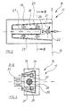
- This emergency exit device 1 is a schematic sectional view through an emergency exit device 1 shown for a motor vehicle.
- This emergency exit device 1 comprises a pyrotechnic device 2 on a vehicle door 3 with a Hinge arrangement 5 connecting vehicle body 4.
- This hinge assembly 5 comprises a hinge pin 6 which, like this can also be seen in particular from FIG. 2, which shows a section along the Line A-A of Fig. 1, in an end hinge eye 7 of a door Hinge part 8 and a guide rail 9 as the body side Hinge part is added.
- the guide rail 9 is for guiding the Hinge eye 7 directed to the outside of the vehicle 10.
- the pyrotechnic device 2 comprises a pyrotechnic device across the hinge eye 7 and thus piston 11 which can be moved towards the hinge pin 6.
- 6 predetermined breaking points are on the hinge pin 12, 13 formed.
- the pyrotechnic device 2 is equipped with an ignition control unit, but here is not shown coupled.
- This ignition control unit can be used for an emergency exit device can be activated via a crash sensor, for example.
Landscapes
- Engineering & Computer Science (AREA)
- Mechanical Engineering (AREA)
- General Engineering & Computer Science (AREA)
- Lock And Its Accessories (AREA)
- Power-Operated Mechanisms For Wings (AREA)
Abstract
Description
- Fig. 1
- eine schematische Schnittdarstellung mit einer ersten Ausführungsform einer Notausstiegvorrichtung für ein Kraftfahrzeug,
- Fig. 2
- eine schematische Schnittdarstellung entlang der Linie A-A der Fig. 1,
- Fig. 3
- eine schematische Schnittdarstellung mit einer zweiten Ausführungsform einer Notausstiegvorrichtung für ein Kraftfahrzeug, und
- Fig. 4
- eine schematische Schnittdarstellung entlang der Linie B-B der Fig. 3.
Claims (12)
- Notausstiegvorrichtung für ein Kraftfahrzeug,dadurch gekennzeichnet,mit wenigstens einer Pyrotechnikeinrichtung an wenigstens einem eine Fahrzeugtür mit einer Karosserie verbindenden Verbindungsbauteil, undmit einer Zündsteuereinheit für die wenigstens eine Pyrotechnikeinrichtung, wobei nach einer Zündung der wenigstens einen Pyrotechnikeinrichtung das Verbindungsbauteil soweit verformt oder zerstört wird, dass die dortige Verbindung zwischen Fahrzeugtür und Karosserie aufgetrennt ist,
dass mittels der wenigstens einen Pyrotechnikeinrichtung (2; 22) zur Auftrennung der Verbindung zwischen Fahrzeugtür (3) und Karosserie (4) und/oder mittels wenigstens einer weiteren zweiten Pyrotechnikeinrichtung (27) nach der Verbindungsauftrennung eine etwa quer zur Türebene der geschlossenen Fahrzeugtür (3) und zur Fahrzeugaußenseite (10; 19) gerichtete Kraftkomponente auf die Fahrzeugtür (3) aufbringbar ist. - Notausstiegvorrichtung insbesondere nach Anspruch 1, dadurch gekennzeichnet, dass die Zündsteuereinheit für eine Notausstiegvorrichtung über einen Crashsensor aktivierbar ist.
- Notausstiegvorrichtung nach Anspruch 1 oder Anspruch 2, dadurch gekennzeichnet, dass die Zündsteuereinheit ein Zeitglied umfasst und die zweite Pyrotechnikeinrichtung (27) zeitversetzt nach der ersten Pyrotechnikeinrichtung (22) zündbar ist.
- Notausstiegvorrichtung nach einem der Ansprüche 1 bis 3, dadurch gekennzeichnet, dass die Zündsteuereinheit nur unterhalb einer bestimmten Fahrzeuggeschwindigkeit, insbesondere bei Fahrzeugstillstand aktivierbar ist.
- Notausstiegvorrichtung nach einem der Ansprüche 1 bis 4, dadurch gekennzeichnet, dass das mit einer Pyrotechnikeinrichtung (2) ausgerüstete Verbindungsbauteil zwischen Fahrzeugtür (3) und Karosserie (4) eine Scharnieranordnung (5) ist.
- Notausstiegvorrichtung nach Anspruch 5, dadurch gekennzeichnet,dass die erste Pyrotechnikeinrichtung (2) einen pyrotechnisch quer auf einen Scharnierbolzen (6) zubewegbaren Kolben (11) umfasst, durch den dieser unmittelbar oder mittelbar, vorzugsweise an Sollbruchstellen (12, 13) zur Verbindungsauftrennung abscherbar ist, unddass mittels des Kolbens (11) weiter die Kraftkomponente in Öffnungsrichtung auf die Fahrzeugtür (3) übertragbar ist.
- Notausstiegvorrichtung nach Anspruch 6, dadurch gekennzeichnet,dass der Scharnierbolzen (6) in einem endseitigen Scharnierauge (7) eines türseitigen Scharnierteils (8) und einer Führungsschiene (9) als karosserieseitiges Scharnierteil aufgenommen ist, wobei die Führungsschiene (9) zur Führung des Scharnierauges (7) zur Fahrzeugaußenseite (10) gerichtet ist,dass der Kolben (11) zur Abscherung des Scharnierbolzens (6) am Scharnierauge (7) angreift, unddass nach dem Abscheren des Scharnierbolzens (6) das in der Führungsschiene (9) geführte Scharnierauge (7) und damit die Fahrzeugtür (3) mittels des pyrotechnisch weiterbewegbaren Kolbens (11) in Öffnungsrichtung aufdrückbar ist.
- Notausstiegvorrichtung nach einem der Ansprüche 1 bis 7, dadurch gekennzeichnet, dass das mit wenigstens einer Pyrotechnikeinrichtung (22; 27) ausgerüstete Verbindungsbauteil zwischen Fahrzeugtür (3) und Karosserie (4) eine Schlossanordnung (17) ist.
- Notausstiegvorrichtung nach Anspruch 8, dadurch gekennzeichnet,dass eine Schlossgrundplatte (18) karosserieseitig fest verbunden ist, die ein zur Fahrzeugaußenseite (19) offenes Führungsprofil (20) enthält,dass in diesem Führungsprofil (20) ein zur Türaußenseite verschiebbarer Türkeilträger (21) formschlüssig aufgenommen und mittels einer pyrotechnisch absprengbaren Sprengschraube (22) als erster Pyrotechnikeinrichtung fixiert ist, unddass in einer Zylinderausnehmung (26) des Türkeilträgers (21) ein pyrotechnisch aktivierbarer, zur Fahrzeuginnenseite hin an der Schlossgrundplatte (18) abgestützter Kolben (27) als zweite Pyrotechnikeinrichtung enthalten ist, wobei bei einer Auslösung der Zündsteuereinheit zuerst die Sprengschraube (22) zur Verbindungsauftrennung absprengbar ist und anschließend der Türkeilträger (21) und die über den Türkeil (23) verbundene Fahrzeugtür (3) mittels des Kolbens (27) aufdrückbar ist.
- Notausstiegvorrichtung nach Anspruch 9, dadurch gekennzeichnet, dass das Führungsprofil (20) schwalbenschwanzförmig hinterschnitten und zur Fahrzeugaußenseite (19) keilförmig erweitert ist und der Türkeilträger (21) entsprechend gestaltet ist.
- Notausstiegvorrichtung nach Anspruch 9 oder Anspruch 10, dadurch gekennzeichnet, dass der Türkeil (23) mittels wenigstens einer Gewindeplatte (24, 25) einstellbar am Türkeilträger (21) gehalten ist.
- Notausstiegvorrichtung nach einem der Ansprüche 1 bis 11, dadurch gekennzeichnet, dass die Notausstiegvorrichtung (1; 16) an wenigstens einer Fahrzeugtür (3), vorzugsweise an jeweils einer Fahrzeugtür (3) an gegenüberliegenden Fahrzeugseiten realisiert ist.
Applications Claiming Priority (2)
| Application Number | Priority Date | Filing Date | Title |
|---|---|---|---|
| DE19960041A DE19960041B4 (de) | 1999-12-13 | 1999-12-13 | Notausstiegvorrichtung für ein Kraftfahrzeug |
| DE19960041 | 1999-12-13 |
Publications (2)
| Publication Number | Publication Date |
|---|---|
| EP1108971A1 true EP1108971A1 (de) | 2001-06-20 |
| EP1108971B1 EP1108971B1 (de) | 2006-11-02 |
Family
ID=7932462
Family Applications (1)
| Application Number | Title | Priority Date | Filing Date |
|---|---|---|---|
| EP00126916A Expired - Lifetime EP1108971B1 (de) | 1999-12-13 | 2000-12-08 | Notausstiegvorrichtung für ein Kraftfahrzeug |
Country Status (3)
| Country | Link |
|---|---|
| EP (1) | EP1108971B1 (de) |
| DE (2) | DE19960041B4 (de) |
| ES (1) | ES2272231T3 (de) |
Cited By (5)
| Publication number | Priority date | Publication date | Assignee | Title |
|---|---|---|---|---|
| WO2004033833A1 (de) * | 2002-10-09 | 2004-04-22 | Novak Wieslaw | System zum notöffnen von kraftfahrzeugtüren |
| WO2005038178A1 (es) * | 2003-10-17 | 2005-04-28 | Delgado Acarreta Raul | Sistema de liberacion para automovil |
| CN105155951A (zh) * | 2015-08-27 | 2015-12-16 | 苏州玄禾物联网科技有限公司 | 一种智能滤波检测铰链 |
| EP2987932A1 (de) * | 2014-08-21 | 2016-02-24 | Audi Ag | Schliesskeilsystem als fahrzeugklappenschloss |
| CN118327395A (zh) * | 2024-06-06 | 2024-07-12 | 厉骏 | 一种碰撞自动解锁的汽车车门装置 |
Families Citing this family (6)
| Publication number | Priority date | Publication date | Assignee | Title |
|---|---|---|---|---|
| DE10337555A1 (de) * | 2003-08-14 | 2005-03-10 | Volkswagen Ag | Kühler zur Kühlung einer Brennkraftmaschine eines Fahrzeuges, insbesondere eines Kraftfahrzeug |
| DE102004018552B3 (de) * | 2004-04-14 | 2005-08-18 | Daimlerchrysler Ag | Einrichtung zum Abkoppeln eines Fahrzeugbauteils von einem Karosserieteil |
| GB2601465B (en) | 2010-01-20 | 2023-03-15 | Secr Defence | Apparatus for breaching a barrier |
| DE102012018601B4 (de) * | 2012-09-20 | 2015-05-07 | Audi Ag | Drehgelenk mit pyrotechnischer Notentriegelung für eine Fahrzeugtür und korrespondierende Fahrzeugtür |
| DE102012018600B4 (de) * | 2012-09-20 | 2015-02-12 | Audi Ag | Drehgelenk mit pyrotechnischer Notentriegelung für eine Fahrzeugtür und korrespondierende Fahrzeugtür |
| IL303490A (en) * | 2020-12-11 | 2023-08-01 | Siemens Mobility GmbH | Safety system for an enclosure |
Citations (8)
| Publication number | Priority date | Publication date | Assignee | Title |
|---|---|---|---|---|
| US3119302A (en) * | 1961-06-05 | 1964-01-28 | Aircraft Armaments Inc | Gas sealed explosive propelling arrangement |
| JPH0234452A (ja) * | 1988-07-26 | 1990-02-05 | Mitsubishi Motors Corp | 自動車の緊急脱出装置 |
| EP0433940A1 (de) | 1989-12-19 | 1991-06-26 | Trasco Export Gmbh | Notausstiegsvorrichtung für Kraftfahrzeuge |
| DE3735133C2 (de) | 1987-10-16 | 1993-08-05 | Bayerische Motoren Werke Ag, 8000 Muenchen, De | |
| DE19547727A1 (de) * | 1995-12-20 | 1997-06-26 | Vdo Schindling | Einrichtung zum Entriegeln von Türen |
| US5727288A (en) * | 1995-03-22 | 1998-03-17 | Daewoo Electronics Co., Ltd. | Apparatus for separating doors frm a body of a motor vehicle |
| DE19803440A1 (de) | 1998-01-29 | 1999-08-12 | Sachsenring Entwicklungsgesell | Notausstieg für Sicherheitskraftfahrzeuge |
| DE19847079A1 (de) * | 1998-10-02 | 2000-04-06 | Brose Fahrzeugteile | Elektrisches Schloß für Kraftfahrzeuge |
Family Cites Families (2)
| Publication number | Priority date | Publication date | Assignee | Title |
|---|---|---|---|---|
| DE19632610A1 (de) * | 1996-08-13 | 1998-02-19 | Dynamit Nobel Ag | Entriegelungsvorrichtung für eine an einer Wandstruktur befestigte Platte |
| DE19733034C2 (de) * | 1997-07-31 | 2003-03-20 | Daimler Chrysler Ag | Notausstieg für Kraftfahrzeuge |
-
1999
- 1999-12-13 DE DE19960041A patent/DE19960041B4/de not_active Expired - Fee Related
-
2000
- 2000-12-08 ES ES00126916T patent/ES2272231T3/es not_active Expired - Lifetime
- 2000-12-08 EP EP00126916A patent/EP1108971B1/de not_active Expired - Lifetime
- 2000-12-08 DE DE50013687T patent/DE50013687D1/de not_active Expired - Lifetime
Patent Citations (8)
| Publication number | Priority date | Publication date | Assignee | Title |
|---|---|---|---|---|
| US3119302A (en) * | 1961-06-05 | 1964-01-28 | Aircraft Armaments Inc | Gas sealed explosive propelling arrangement |
| DE3735133C2 (de) | 1987-10-16 | 1993-08-05 | Bayerische Motoren Werke Ag, 8000 Muenchen, De | |
| JPH0234452A (ja) * | 1988-07-26 | 1990-02-05 | Mitsubishi Motors Corp | 自動車の緊急脱出装置 |
| EP0433940A1 (de) | 1989-12-19 | 1991-06-26 | Trasco Export Gmbh | Notausstiegsvorrichtung für Kraftfahrzeuge |
| US5727288A (en) * | 1995-03-22 | 1998-03-17 | Daewoo Electronics Co., Ltd. | Apparatus for separating doors frm a body of a motor vehicle |
| DE19547727A1 (de) * | 1995-12-20 | 1997-06-26 | Vdo Schindling | Einrichtung zum Entriegeln von Türen |
| DE19803440A1 (de) | 1998-01-29 | 1999-08-12 | Sachsenring Entwicklungsgesell | Notausstieg für Sicherheitskraftfahrzeuge |
| DE19847079A1 (de) * | 1998-10-02 | 2000-04-06 | Brose Fahrzeugteile | Elektrisches Schloß für Kraftfahrzeuge |
Non-Patent Citations (1)
| Title |
|---|
| PATENT ABSTRACTS OF JAPAN vol. 014, no. 186 (M - 0962) 16 April 1990 (1990-04-16) * |
Cited By (6)
| Publication number | Priority date | Publication date | Assignee | Title |
|---|---|---|---|---|
| WO2004033833A1 (de) * | 2002-10-09 | 2004-04-22 | Novak Wieslaw | System zum notöffnen von kraftfahrzeugtüren |
| WO2005038178A1 (es) * | 2003-10-17 | 2005-04-28 | Delgado Acarreta Raul | Sistema de liberacion para automovil |
| EP2987932A1 (de) * | 2014-08-21 | 2016-02-24 | Audi Ag | Schliesskeilsystem als fahrzeugklappenschloss |
| CN105155951A (zh) * | 2015-08-27 | 2015-12-16 | 苏州玄禾物联网科技有限公司 | 一种智能滤波检测铰链 |
| CN105155951B (zh) * | 2015-08-27 | 2017-04-05 | 苏州玄禾物联网科技有限公司 | 一种智能滤波检测铰链 |
| CN118327395A (zh) * | 2024-06-06 | 2024-07-12 | 厉骏 | 一种碰撞自动解锁的汽车车门装置 |
Also Published As
| Publication number | Publication date |
|---|---|
| ES2272231T3 (es) | 2007-05-01 |
| DE50013687D1 (de) | 2006-12-14 |
| EP1108971B1 (de) | 2006-11-02 |
| DE19960041A1 (de) | 2001-07-05 |
| DE19960041B4 (de) | 2004-08-19 |
Similar Documents
| Publication | Publication Date | Title |
|---|---|---|
| DE4016611C2 (de) | ||
| DE10066268B4 (de) | Sicherheitssystem für ein Kraftfahrzeug | |
| DE19964304B4 (de) | Fronthaubenanordnung | |
| DE102011117798B4 (de) | Sicherheitseinrichtung für ein Fahrzeug | |
| DE10016142B4 (de) | Auslöseschalter für ein Personenschutzsystem | |
| WO2019185704A1 (de) | Lenksäule für ein kraftfahrzeug | |
| DE10309821A1 (de) | Kraftfahrzeug | |
| EP1108971B1 (de) | Notausstiegvorrichtung für ein Kraftfahrzeug | |
| EP0433940B1 (de) | Notausstiegsvorrichtung für Kraftfahrzeuge | |
| DE60015409T2 (de) | Vorrichtung zum Befestigen einer Glasscheibe für Kraftfahrzeuge | |
| DE69412671T2 (de) | Luftsack-Deckel | |
| DE10128864B4 (de) | Fahrzeugtür mit einer Sicherheitseinrichtung | |
| DE19757363B4 (de) | Airbagsystem für Kraftfahrzeuge | |
| DE102009038612A9 (de) | Griffelement mit einer Crashsperre | |
| DE10222512A1 (de) | Energieabsorbierendes Karosserieteil, insbesondere Fronthaube, für ein Fahrzeug, insbesondere Kraftfahrzeug | |
| EP0953485B1 (de) | Aufprall-Schutzvorrichtung | |
| WO2024012623A1 (de) | Aufstellvorrichtung für eine kraftfahrzeugtür | |
| DE102009022533A1 (de) | Notausstiegsvorrichtung für Türen, Wände und Strukturteile auf Basis kommandiert verschiebbarem Bolzen | |
| DE19947363B4 (de) | Notöffnungsvorrichtung für eine Kraftfahrzeugtür | |
| DE102016200315A1 (de) | Heckklappe eines Fahrzeugs | |
| DE102014012466B4 (de) | Schließkeilsystem als Fahrzeugklappenschloss | |
| DE10244138B4 (de) | Halterung einer Fensterscheibe eines Kraftfahrzeugs | |
| WO2020201441A1 (de) | Schlosshalter für ein kraftfahrzeugtürschloss | |
| DE10324890A1 (de) | Kraftfahrzeug | |
| DE102007002125A1 (de) | Aufprallschutzvorrichtung |
Legal Events
| Date | Code | Title | Description |
|---|---|---|---|
| PUAI | Public reference made under article 153(3) epc to a published international application that has entered the european phase |
Free format text: ORIGINAL CODE: 0009012 |
|
| AK | Designated contracting states |
Kind code of ref document: A1 Designated state(s): DE ES FR GB IT |
|
| AX | Request for extension of the european patent |
Free format text: AL;LT;LV;MK;RO;SI |
|
| 17P | Request for examination filed |
Effective date: 20010525 |
|
| AKX | Designation fees paid |
Free format text: DE ES FR GB IT |
|
| 17Q | First examination report despatched |
Effective date: 20041201 |
|
| GRAP | Despatch of communication of intention to grant a patent |
Free format text: ORIGINAL CODE: EPIDOSNIGR1 |
|
| GRAS | Grant fee paid |
Free format text: ORIGINAL CODE: EPIDOSNIGR3 |
|
| GRAA | (expected) grant |
Free format text: ORIGINAL CODE: 0009210 |
|
| AK | Designated contracting states |
Kind code of ref document: B1 Designated state(s): DE ES FR GB IT |
|
| REG | Reference to a national code |
Ref country code: GB Ref legal event code: FG4D Free format text: NOT ENGLISH |
|
| REF | Corresponds to: |
Ref document number: 50013687 Country of ref document: DE Date of ref document: 20061214 Kind code of ref document: P |
|
| GBT | Gb: translation of ep patent filed (gb section 77(6)(a)/1977) |
Effective date: 20061220 |
|
| ET | Fr: translation filed | ||
| REG | Reference to a national code |
Ref country code: ES Ref legal event code: FG2A Ref document number: 2272231 Country of ref document: ES Kind code of ref document: T3 |
|
| PLBE | No opposition filed within time limit |
Free format text: ORIGINAL CODE: 0009261 |
|
| STAA | Information on the status of an ep patent application or granted ep patent |
Free format text: STATUS: NO OPPOSITION FILED WITHIN TIME LIMIT |
|
| 26N | No opposition filed |
Effective date: 20070803 |
|
| REG | Reference to a national code |
Ref country code: FR Ref legal event code: PLFP Year of fee payment: 16 |
|
| REG | Reference to a national code |
Ref country code: FR Ref legal event code: PLFP Year of fee payment: 17 |
|
| REG | Reference to a national code |
Ref country code: FR Ref legal event code: PLFP Year of fee payment: 18 |
|
| PGFP | Annual fee paid to national office [announced via postgrant information from national office to epo] |
Ref country code: DE Payment date: 20171231 Year of fee payment: 18 |
|
| PGFP | Annual fee paid to national office [announced via postgrant information from national office to epo] |
Ref country code: FR Payment date: 20181221 Year of fee payment: 19 Ref country code: GB Payment date: 20181220 Year of fee payment: 19 |
|
| PGFP | Annual fee paid to national office [announced via postgrant information from national office to epo] |
Ref country code: ES Payment date: 20190115 Year of fee payment: 19 Ref country code: IT Payment date: 20181231 Year of fee payment: 19 |
|
| REG | Reference to a national code |
Ref country code: DE Ref legal event code: R119 Ref document number: 50013687 Country of ref document: DE |
|
| PG25 | Lapsed in a contracting state [announced via postgrant information from national office to epo] |
Ref country code: DE Free format text: LAPSE BECAUSE OF NON-PAYMENT OF DUE FEES Effective date: 20190702 |
|
| GBPC | Gb: european patent ceased through non-payment of renewal fee |
Effective date: 20191208 |
|
| PG25 | Lapsed in a contracting state [announced via postgrant information from national office to epo] |
Ref country code: FR Free format text: LAPSE BECAUSE OF NON-PAYMENT OF DUE FEES Effective date: 20191231 Ref country code: IT Free format text: LAPSE BECAUSE OF NON-PAYMENT OF DUE FEES Effective date: 20191208 Ref country code: GB Free format text: LAPSE BECAUSE OF NON-PAYMENT OF DUE FEES Effective date: 20191208 |
|
| REG | Reference to a national code |
Ref country code: ES Ref legal event code: FD2A Effective date: 20210531 |
|
| PG25 | Lapsed in a contracting state [announced via postgrant information from national office to epo] |
Ref country code: ES Free format text: LAPSE BECAUSE OF NON-PAYMENT OF DUE FEES Effective date: 20191209 |