EP1108799B1 - High strength Mg based alloy and its uses - Google Patents
High strength Mg based alloy and its uses Download PDFInfo
- Publication number
- EP1108799B1 EP1108799B1 EP00125394A EP00125394A EP1108799B1 EP 1108799 B1 EP1108799 B1 EP 1108799B1 EP 00125394 A EP00125394 A EP 00125394A EP 00125394 A EP00125394 A EP 00125394A EP 1108799 B1 EP1108799 B1 EP 1108799B1
- Authority
- EP
- European Patent Office
- Prior art keywords
- alloy according
- alloy
- based alloy
- high strength
- content
- Prior art date
- Legal status (The legal status is an assumption and is not a legal conclusion. Google has not performed a legal analysis and makes no representation as to the accuracy of the status listed.)
- Expired - Lifetime
Links
- 239000000956 alloy Substances 0.000 title claims description 149
- 229910045601 alloy Inorganic materials 0.000 title claims description 148
- 229910052751 metal Inorganic materials 0.000 claims description 23
- 239000002184 metal Substances 0.000 claims description 23
- 229910052782 aluminium Inorganic materials 0.000 claims description 17
- 229910052725 zinc Inorganic materials 0.000 claims description 17
- 229910052749 magnesium Inorganic materials 0.000 claims description 14
- 229910052718 tin Inorganic materials 0.000 claims description 14
- 239000000203 mixture Substances 0.000 claims description 9
- 239000007791 liquid phase Substances 0.000 claims description 8
- 229910052748 manganese Inorganic materials 0.000 claims description 8
- 239000004973 liquid crystal related substance Substances 0.000 claims description 6
- 239000007790 solid phase Substances 0.000 claims description 6
- 229910052791 calcium Inorganic materials 0.000 claims description 5
- 229910052710 silicon Inorganic materials 0.000 claims description 5
- 239000013078 crystal Substances 0.000 claims description 4
- 239000012535 impurity Substances 0.000 claims description 3
- 239000007787 solid Substances 0.000 claims description 3
- 229910052761 rare earth metal Inorganic materials 0.000 claims description 2
- 239000011777 magnesium Substances 0.000 description 49
- 230000008018 melting Effects 0.000 description 28
- 238000002844 melting Methods 0.000 description 28
- 238000001746 injection moulding Methods 0.000 description 25
- 239000011701 zinc Substances 0.000 description 21
- 230000007797 corrosion Effects 0.000 description 16
- 238000005260 corrosion Methods 0.000 description 16
- 239000012071 phase Substances 0.000 description 15
- 229910000861 Mg alloy Inorganic materials 0.000 description 14
- 238000002347 injection Methods 0.000 description 13
- 239000007924 injection Substances 0.000 description 13
- 238000000465 moulding Methods 0.000 description 13
- 238000005266 casting Methods 0.000 description 12
- 230000003247 decreasing effect Effects 0.000 description 11
- 230000000694 effects Effects 0.000 description 11
- FYYHWMGAXLPEAU-UHFFFAOYSA-N Magnesium Chemical compound [Mg] FYYHWMGAXLPEAU-UHFFFAOYSA-N 0.000 description 10
- 238000000034 method Methods 0.000 description 10
- 239000002994 raw material Substances 0.000 description 10
- 238000012360 testing method Methods 0.000 description 10
- 229910000765 intermetallic Inorganic materials 0.000 description 9
- 229910003023 Mg-Al Inorganic materials 0.000 description 8
- 230000007547 defect Effects 0.000 description 8
- 150000001875 compounds Chemical class 0.000 description 6
- 238000004512 die casting Methods 0.000 description 6
- XEEYBQQBJWHFJM-UHFFFAOYSA-N iron Substances [Fe] XEEYBQQBJWHFJM-UHFFFAOYSA-N 0.000 description 6
- XLYOFNOQVPJJNP-UHFFFAOYSA-N water Substances O XLYOFNOQVPJJNP-UHFFFAOYSA-N 0.000 description 6
- 229910019074 Mg-Sn Inorganic materials 0.000 description 5
- 229910019382 Mg—Sn Inorganic materials 0.000 description 5
- 239000007864 aqueous solution Substances 0.000 description 5
- 239000000463 material Substances 0.000 description 5
- TWRXJAOTZQYOKJ-UHFFFAOYSA-L Magnesium chloride Chemical compound [Mg+2].[Cl-].[Cl-] TWRXJAOTZQYOKJ-UHFFFAOYSA-L 0.000 description 4
- 230000004907 flux Effects 0.000 description 4
- 239000003973 paint Substances 0.000 description 4
- 229920006395 saturated elastomer Polymers 0.000 description 4
- 238000007711 solidification Methods 0.000 description 4
- 230000008023 solidification Effects 0.000 description 4
- 230000000052 comparative effect Effects 0.000 description 3
- 238000001816 cooling Methods 0.000 description 3
- 238000007654 immersion Methods 0.000 description 3
- 230000002940 repellent Effects 0.000 description 3
- 239000005871 repellent Substances 0.000 description 3
- 238000012795 verification Methods 0.000 description 3
- KRHYYFGTRYWZRS-UHFFFAOYSA-M Fluoride anion Chemical compound [F-] KRHYYFGTRYWZRS-UHFFFAOYSA-M 0.000 description 2
- 229910001122 Mischmetal Inorganic materials 0.000 description 2
- 229910004835 Na2B4O7 Inorganic materials 0.000 description 2
- FAPWRFPIFSIZLT-UHFFFAOYSA-M Sodium chloride Chemical compound [Na+].[Cl-] FAPWRFPIFSIZLT-UHFFFAOYSA-M 0.000 description 2
- HCHKCACWOHOZIP-UHFFFAOYSA-N Zinc Chemical compound [Zn] HCHKCACWOHOZIP-UHFFFAOYSA-N 0.000 description 2
- 239000011248 coating agent Substances 0.000 description 2
- 238000000576 coating method Methods 0.000 description 2
- 238000010586 diagram Methods 0.000 description 2
- 230000017525 heat dissipation Effects 0.000 description 2
- 229910052742 iron Inorganic materials 0.000 description 2
- 150000002680 magnesium Chemical class 0.000 description 2
- 229910001629 magnesium chloride Inorganic materials 0.000 description 2
- 238000004519 manufacturing process Methods 0.000 description 2
- 230000003647 oxidation Effects 0.000 description 2
- 238000007254 oxidation reaction Methods 0.000 description 2
- 230000003449 preventive effect Effects 0.000 description 2
- 230000008569 process Effects 0.000 description 2
- 150000003839 salts Chemical class 0.000 description 2
- 239000002893 slag Substances 0.000 description 2
- 229910000679 solder Inorganic materials 0.000 description 2
- 239000000243 solution Substances 0.000 description 2
- 239000007921 spray Substances 0.000 description 2
- 238000003756 stirring Methods 0.000 description 2
- 238000009864 tensile test Methods 0.000 description 2
- 229910018131 Al-Mn Inorganic materials 0.000 description 1
- 229910018461 Al—Mn Inorganic materials 0.000 description 1
- 229910000549 Am alloy Inorganic materials 0.000 description 1
- 229910052684 Cerium Inorganic materials 0.000 description 1
- 229910004619 Na2MoO4 Inorganic materials 0.000 description 1
- 239000007832 Na2SO4 Substances 0.000 description 1
- 229910006639 Si—Mn Inorganic materials 0.000 description 1
- 229910001128 Sn alloy Inorganic materials 0.000 description 1
- PMZURENOXWZQFD-UHFFFAOYSA-L Sodium Sulfate Chemical compound [Na+].[Na+].[O-]S([O-])(=O)=O PMZURENOXWZQFD-UHFFFAOYSA-L 0.000 description 1
- QAOWNCQODCNURD-UHFFFAOYSA-N Sulfuric acid Chemical compound OS(O)(=O)=O QAOWNCQODCNURD-UHFFFAOYSA-N 0.000 description 1
- 229910001297 Zn alloy Inorganic materials 0.000 description 1
- 238000005275 alloying Methods 0.000 description 1
- 230000008901 benefit Effects 0.000 description 1
- 229910052797 bismuth Inorganic materials 0.000 description 1
- 210000004027 cell Anatomy 0.000 description 1
- 210000003850 cellular structure Anatomy 0.000 description 1
- 230000008859 change Effects 0.000 description 1
- 238000010276 construction Methods 0.000 description 1
- 230000008602 contraction Effects 0.000 description 1
- 238000005520 cutting process Methods 0.000 description 1
- UQGFMSUEHSUPRD-UHFFFAOYSA-N disodium;3,7-dioxido-2,4,6,8,9-pentaoxa-1,3,5,7-tetraborabicyclo[3.3.1]nonane Chemical compound [Na+].[Na+].O1B([O-])OB2OB([O-])OB1O2 UQGFMSUEHSUPRD-UHFFFAOYSA-N 0.000 description 1
- 230000005496 eutectics Effects 0.000 description 1
- 238000011156 evaluation Methods 0.000 description 1
- 239000003779 heat-resistant material Substances 0.000 description 1
- 229910001385 heavy metal Inorganic materials 0.000 description 1
- 230000006872 improvement Effects 0.000 description 1
- 238000011835 investigation Methods 0.000 description 1
- 229910052746 lanthanum Inorganic materials 0.000 description 1
- 238000005259 measurement Methods 0.000 description 1
- 230000007246 mechanism Effects 0.000 description 1
- 238000003801 milling Methods 0.000 description 1
- 229910052750 molybdenum Inorganic materials 0.000 description 1
- 239000008188 pellet Substances 0.000 description 1
- 229960004624 perflexane Drugs 0.000 description 1
- ZJIJAJXFLBMLCK-UHFFFAOYSA-N perfluorohexane Chemical compound FC(F)(F)C(F)(F)C(F)(F)C(F)(F)C(F)(F)C(F)(F)F ZJIJAJXFLBMLCK-UHFFFAOYSA-N 0.000 description 1
- 238000004881 precipitation hardening Methods 0.000 description 1
- 238000012545 processing Methods 0.000 description 1
- 238000004904 shortening Methods 0.000 description 1
- 239000011780 sodium chloride Substances 0.000 description 1
- 239000011684 sodium molybdate Substances 0.000 description 1
- 229910052938 sodium sulfate Inorganic materials 0.000 description 1
- 239000006104 solid solution Substances 0.000 description 1
- 230000009974 thixotropic effect Effects 0.000 description 1
Images






Classifications
-
- C—CHEMISTRY; METALLURGY
- C22—METALLURGY; FERROUS OR NON-FERROUS ALLOYS; TREATMENT OF ALLOYS OR NON-FERROUS METALS
- C22C—ALLOYS
- C22C23/00—Alloys based on magnesium
-
- C—CHEMISTRY; METALLURGY
- C22—METALLURGY; FERROUS OR NON-FERROUS ALLOYS; TREATMENT OF ALLOYS OR NON-FERROUS METALS
- C22C—ALLOYS
- C22C1/00—Making non-ferrous alloys
- C22C1/12—Making non-ferrous alloys by processing in a semi-solid state, e.g. holding the alloy in the solid-liquid phase
-
- C—CHEMISTRY; METALLURGY
- C22—METALLURGY; FERROUS OR NON-FERROUS ALLOYS; TREATMENT OF ALLOYS OR NON-FERROUS METALS
- C22C—ALLOYS
- C22C23/00—Alloys based on magnesium
- C22C23/02—Alloys based on magnesium with aluminium as the next major constituent
-
- C—CHEMISTRY; METALLURGY
- C22—METALLURGY; FERROUS OR NON-FERROUS ALLOYS; TREATMENT OF ALLOYS OR NON-FERROUS METALS
- C22C—ALLOYS
- C22C23/00—Alloys based on magnesium
- C22C23/04—Alloys based on magnesium with zinc or cadmium as the next major constituent
Definitions
- the present invention relates to a novel Mg based alloy and a novel Mg casting alloy capable of mass producing OA parts, car parts, electric appliance parts and so on through die casting, injection molding or the like, and relates to articles mold-cast using the alloy.
- the casting Mg alloys practically used in present time are as follows:
- the alloy (1) is most commonly used as the die casting and the injection molding Mg alloy, and particularly the AZ91D is good in die-castability and in corrosion resistance and widely applied to car parts and electric appliance parts.
- the alloys (2), (3) are alloys improving the mechanical properties such as the creep property and the high temperature strength. As the prior art in regard to these alloys, various kinds of alloys are disclosed in the following patent gazettes.
- Japanese Patent Application Laid-Open No.6-330216 discloses an Mg based alloy containing Ca, Si, Al, Zn and Mn
- Japanese Patent Application Laid-Open No.9-104942 discloses an Mg based alloy containing 5 to 10 of Al, 0.2 to 1 of Si and 0.05 to 0.5 of Cu
- Japanese Patent Application Laid-Open No.10-147830 discloses an Mg based alloy containing 1 to 6 of Gd and 6 to 12 of Y.
- US-A-2 000 115 discloses a magnesium-based alloy having an improved hot working performance, containing 0.5 to 10.0 % Al, 0.1 to 12 % Sn, 0.1 to 1.0 % Mn, and Zn and/or Cd in an amount of 0.1 to 5.0 %, the balance being Mg.
- GB-A-2 058 837 describes a magnesium alloy containing 1 to 9 % Al, 0 to 4 % Zn, 0.1 to 5 % Sn, 0 to 1 % Mn, which is used as an anode in electric cells.
- GB-A-1 291 553 describes an Mg-based alloy having 5.5 to 10 % Al, 0.3 to 2 % Zn and 0.1 to 0.4 % Sb or Sn for preventing hot crack during die casting of the alloy.
- US-A-3 653 880 describes a magnesium based cast alloy having a little tendency to hot-crack, with a composition of 3 to 10 % Al, 0.3 to 2 % Zn and 0.1 to 0.4 % Sb or Sn.
- DE-A-19 34 617 discloses a magnesium alloy containing 3-30% Al, 0.3-2% Zn, 0.05-0.5 Bi or Sn, up to 0.5 % Mn, up to 0.5 % Si, up to 0.5 Cu.
- the alloy (1) of AZ91D described above is comparatively high in the fluidity, but the molding yield in injection molding is not always sufficiently high.
- the alloy groups (2), (3) are prior to AZ91D in the mechanical properties such as creep property, strength at high temperature. However, because of the bad fluidity, the alloy groups (2), (3) are apt to cause casting cracks in the molding method of high speed cooling such as the injection molding method and are bad in castability.
- the fluidity may be improved by raising the temperature of molten alloy.
- raising of the molten alloy temperature has problems in oxidation of the molten alloy and in shortening of durable lifetime of the production machines. Therefore, it is necessary to improve the fluidity by the other method.
- the solidification structure of AZ91D becomes dendritic when it is cooled in a comparatively slow speed such as at ingot casting.
- the alloy is designed by placing special emphasis on the molten fluidity, and in regard to the properties after solidification, the alloy is designed so that the various kinds of properties such as the mechanical properties are optimized on the premise that the structure of AZ91D becomes dendritic.
- An object of the present invention is to provide a high strength Mg based alloy and a Mg based casting alloy having a good fluidity and a good mechanical property, and a cast article using the alloy.
- the alloy according to the invention has a crystal size of 10 to 300 ⁇ m.
- a high strength Mg based alloy contains 12 to 15 % of Al by weight; 0.1 to 5 % of Zn; 1 to 10 % of Sn; 0.1 to 0.5 % of Mn, and the remainder contains Mg more than 75 %.
- a Mg based casting alloy according to the invention may contain 12 to 15 % of Al by weight; 0.5 to 3 % of Zn; 1.5 to 4.5 % of Sn; 0.05 to 0.5 % of Mn.
- the present invention provides a die cast article or injection molding article, which is casted using a molten metal of any one of the alloys described above.
- the present invention provides a thixotropic mold article, which is molded using a molten metal of a mixture of liquid phase and solid phase of any one of the alloys described above.
- the magnesium based alloys described above are formed in desirable shapes through die casting by injection molding.
- the magnesium alloys in accordance with the present invention are improved in the fluidity due to lowering of the melting point particularly by adding a small amount of Sn to the Mg based alloy containing Al, and accordingly members having less surface defects can be obtained. Further, since low temperature molding can be performed and accordingly the contraction at solidifying is small, members having a high dimensional accuracy can be obtained. Therefore, the molding yield can be largely improved.
- the durable lifetime of the heat resistant materials can be lengthened.
- magnesium alloys in accordance with the present invention are good in mechanical property and corrosion resistance because of the homogeneous and fine microstructure.
- the element Al is added above 12 %.
- an excessive addition exceeding 20 % of the element Al produces a large grain Mg-Al intermetallic compound to substantially decrease the elongation of the molded products.
- the solidified structure becomes finer as the content of Al is increased, and the Mg-Al intermetallic compound does not grow large-sized, but is finely distributed in the crystal grain boundaries. This effect becomes obvious particularly when Sn is added together.
- the element Al in the magnesium alloy in accordance with the present invention is solved in the ⁇ -Mg phase,and reduce the melting point of the alloy. Further, the element Al is solid-solved in the ⁇ -Mg phase and crystallizes the Mg-Al intermetallic compound,with theresult that the strength at room temperature of the alloy is improved. Furthermore, the element Al suppresses oxidation of the molten alloy, and improves fluidity of the molten alloy. In order to attain these effects, the Al content is above 12 %, and preferably above 15 %.
- the element Sn is solved in the ⁇ -Mg phase ,and reduce the melting point of the alloy with a small amount of nearly 0.1 %, particularly more than 0.5 %. Further, the element Sn is solved in the ⁇ -Mg phase and crystallizes the Mg-Sn intermetallic compound,as a result the strength at room temperature is improved. Furthermore, the effect of Sn on lowering the melting point becomes obvious particularly when Al and Zn are added together, but the effect is almost saturated when the Sn content becomes 5 %. Further, when the Sn content exceeds 15 %, the elongation is largely decreased, and the density of the alloy becomes large,and lose the advantage of lightness of the magnesium alloy.
- the Sn content needs to be lower than 10 % in order to keep the elongation above 3.5 %, and the Sn content needs to be preferably lower than 8 % in order to keep the elongation above 4 %.
- the Sn content is 1 to 7 %, it is possible to obtain an alloy having both of high strength and high elongation.
- the element Zn is added above 0.1 % in order to improve the strength at room temperature and the castability. However, when the Zn content exceeds 10 %, casting cracks are apt to occur. It is preferable that the Zn content is within a range of 0.1 to 5 %,preferably 1 to 5% in which the strength is high and the casting cracks do not occur.
- the element Mn improve the corrosion resistance. This is because Mn forms a intermetallic compound with Al ,and fix Fe in the intermetallic compound, the element Fe being contained in the alloy as an impurity deteriorate the corrosion resistance.
- the upper limit of Mn content is set to 1 %.
- Mn content is effective above 0.05 %, and preferably 0.1 to 0.5 %.
- the alloy in accordance with the present invention further contains at least one element selected from the group consisting of Ca, Si and rear-earth elements, the content of the one kind or in total being less than 5 %; and at least one element selected from the group consisting of Sr and Sb, the content of the one kind or in total being less than 1 %.
- the elements Ca and Si and rear-earth elements are effective to lower the melting point because these elements form eutectic groups with Mg.
- the upper limit of the content is 5 %. Particularly, it is preferable that the content is above 0.1 % and the upper limit is set to 3 %.
- the elements Sr and Sb make the metallic structure fine,and to improve the mechanical properties.
- the effect of elements Sr and Sb is increased when the element Si or Ca is added together.
- the effect of elements Sr and Sb is increased as the content is increased, but the effect is saturated when the content exceeds 1 %. Therefore, the upper limit is set to 1 %. Particularly, it is preferable that the content is above 0.03 %, and the upper limit is set to 0.5 %.
- the Mg based alloy in accordance with the present invention is characterized that the surface is covered with an oxide film which contains Mg of 15 to 35 % by atoms; preferably 20 to 30 %, and Mo of 5 to 20 %.
- the Mg based alloy in accordance with the present invention is characterized that the surface is covered with an oxide film which contains Mg of 15 to 35 % by atoms; Mo of 5 to 20; and metallic Al of less than 30 %, preferably 10 to 25 %.
- the Mg based alloy in accordance with the present invention is characterized that the surface is covered with an oxide film which contains Mg of 15 to 35 % by atoms; Mo of 5 to 20; oxide Al of less than 15 %; and metallic Al of less than 15 %, preferably 4 to 12 %.
- the Mg based alloy in accordance with the present invention is characterized that the surface is covered with an inert oxide film of which a natural immersion electric potential 30 minutes after immersing into an aqueous solution of 0.01 mol Na 2 B 4 O 7 , pH 9.2, 25 °C is higher than -1500 mV, preferably higher than - 1400 mV.
- the Mg based alloy in accordance with the present invention is characterized that the surface is covered with an oxide film of which a natural immersion electric potential 15 minutes after immersing into an aqueous solution of 0.01 mol Na 2 SO 4 , 25 °C is higher than -1500 mV, preferably higher than -1400 mV. Further, the Mg based alloy in accordance with the present invention is characterized that the surface is covered with the above-described oxide film or a specified oxide film, and a water repellent organic film containing fluoride is further coated on the oxide film.
- a magnesium chloride type flux was applied on the inner surface of a melting pot made of casting iron pre-heated in an electric furnace, and raw materials were put into the melting pot so as to form an alloy having a composition (weight %) shown in Table 1 to be melted.
- the molten metal was cast in a metal mold of 50 mm ⁇ 50 mm ⁇ 300 mm pre-heated to 150 °C to fabricate a Mg alloy ingot.
- the flux was sprinkled on the molten alloy surface, if necessary.Mm is a mischmetal (La50wt%-Ce50wt% alloy).
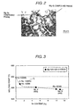
- FIG. 2 shows a typical metallic structure of an alloy obtained through the method as described above.
- Mg-Al compound phase (white portions) are crystallized in a network shape in the ⁇ -phase grain boundary, and Mg-Sn compound phase (black portions) are crystallized between the network of the Mg-Al compound phase.
- FIG. 3 shows measured results of melting points of the alloys, particularly the relationship between the melting point and Sn content for the alloys No. 1 to 3 and 11 to 13.
- the alloy melting point is decreased as the Sn content is increased, and the effect of Sn addition on the melting point is saturated when the its content exceeds 10 Wt%.
- the melting point of the alloy No. 12 containing Al and Zn contents less than the specified values of the present invention is small in the melting point fall from AZ91D alloy (No. 11).
- the melting point is steeply decreased as the Sn content is increased up to the Sn content of 2 %, but mildly decrease where the Sn content is above 2 %.
- the melting point is lower than that596 °C of AZ91D.
- a magnesium chloride type flux was applied on the inner surface of a melting pot made of casting iron pre-heated in an electric furnace, and raw materials were put into the melting pot so as to form an alloy having a composition (weight %) shown in Table 1 to be melted.
- the molten metal was cast in a metal mold of 50 mm ⁇ 50 mm ⁇ 300 mm pre-heated to 150 °C to fabricate a Mg alloy ingot.
- the flux was sprinkled on the molten alloy surface, if necessary.
- An alloy chip of 2 mm to 10 mm diameter was fabricated by milling the ingot obtained through the method as described above, and used as a raw material for injection molding.
- a machine having a mold clamping force of 75 t was used for the injection molding to form an injection molded piece of 120 mm ⁇ 50 mm ⁇ 1 mm thickness.
- the molding condition was as follows.
- a Mm (mischmetal) indicates an alloy containg 50 wt % La and 50 wt % Ce.
- Strength evaluation tests (hardness, tensile strength, elongation) were conducted by obtaining the following test pieces from the molded pieces obtained as described above.
- Test piece 1 mm thickness, 12 mm gage length, 16 mm length and 10 mm width of parallel part.
- Tensile test Using an Instron testing machine, measurement was performed under the condition of 0.3/min strain speed and at 25 °C.
- test pieces No. 1 to 10 and 13 are samples each within the composition range of the embodiment of the present invention, and the test pieces No. 11, 12, 14 and 15 are comparative examples out of the composition range of the embodiment of the present invention (the test piece No. 11 is AZ91D standard alloy).
- Alloy No. Al Zn Sn Mn Others Mg 1 12 3 1 0.2 - bal. 2 12 3 5 0.2 - bal. 3 12 3 10 0.2 - bal. 4 12 5 5 0.2 - bal. 5 15 3 5 0.2 - bal. 6 18 3 5 0.2 - bal. 7 20 3 5 0.2 - bal. 8 12 1 3 0.2 Si: 1, Sr: 0.05 bal. 9 12 1 3 0.2 Ca: 2, Sb: 0.05 bal.
- FIG. 1 is a cross-sectional view showing the main portion of the injection molding machine used in the present embodiment.
- An alloy raw material 1 for injection molding is put into a hopper 2 to be supplied into a cylinder 4.
- the raw material is kneaded and mixed in the cylinder 4 while being transferred toward a nozzle 6 by a rotating screw 5, and at the same time heated by a cylinder heater 7.
- the alloy raw material is injection molded under a melted state where the heated temperature is higher than the liquid-phase line temperature, or under a semi-melted state where a solid phase having a temperature lower than the liquid-phase line temperature and a liquid phase are mixed.
- the melted state or semi-melted state molten metal 10 of the raw alloy material transferred to the front portion of the screw 5 is filled into a metal mold 9 though the nozzle 6 by moving the screw forward using a high speed injection mechanism 8.
- the screw 5 has a spiral blade 13 on a cylindrical solid based body 14, and the alloy raw material 1 is heated up to a high temperature to be made the melted state or the semi-melted state depending on the temperature of the heater 7 while being kneaded with the blade 13 by rotation of the screw 5.
- the reference character 12 is a backflow preventing ring for the molten metal 10.
- the alloy raw material 1 used in the present embodiment is prepared by melting an alloy of each of the compositions under a non-oxidized atmosphere, and then by cutting the formed alloy into chips smaller than 10 mm to form grains of the raw material.
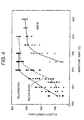
- Figure 4 is a diagram that shows the relationship between the injection temperature and fluidity lengths for both the magnesium-based alloy No.2 in the present invention, an alloy AZ91D in a prior art.
- the cylinder temperature is the temperature at which alloys were molded for their fluidity length verification.
- the fluidity length of an alloy is the length for such sound portion in an injection-molded alloy that has no surface-defects like crack.
- the fluidity length was verified using a fluidity length verification metallic mold having a width of 10 mm, a thickness of 1 mm, and an overall length of 380 mm, intowhich each alloy to be verified was injection-molded by an injection molding apparatus shown in Figure 1 keeping the verification metallic mold constantly at 200°C.
- alloy in the present invention has higher fluidity length performance than alloy AZ91D at any temperature in our investigation.
- the alloy No.12 that includes 3 % zinc spread its fluidity length to about 350 mm at 570°C and another alloy in the present invention that includes 1 % zinc also spreads to about 350 mm at 580°C.
- FIG. 5 to FIG. 7 are graphs showing the relationships between Sn content and test results of hardness and tensile strength of the injection molded article made of each of the alloys shown in Table 1. As shown in the graphs, by adding Sn by 1 %, both of the hardness and the tensile strength become above Hv 110 in hardness and above 269 MPa in tensile strength, respectively. On the other hand, the elongation ratio is improved until the Sn content is increased up to 5 wt%, but is decreased when the Sn content exceeds 5 %, and is steeply decreased to a value before adding Sn when the Sn content exceeds 9 %.
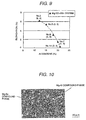
- FIG. 8 and FIG. 9 are graphs showing results of tensile test when the Al content is varied on the basis of the alloy No. 2 (Mg-12Al-3Zn-5Sn). As shown in the graphs, the tensile strength is improved with increasing the Al content, and the tensile above 279 MPa can be obtained up to 12 % of Al content. In regard to the elongation ratio, the elongation ratio above 1.9 % can be obtained up to 20 % of Al content. However, when the Al content exceeds 20 %, the elongation ratio is extremely decreased to a value smaller than 1 %, which is impractical.
- FIG. 10 shows the photograph of the structure of the injection molded article made of the alloy No.2.
- the ⁇ -phase grains having size of nearly 1 to 20 ⁇ m, mainly less than 5 ⁇ m and the Mg-Al compound phase crystallized in network shape in the grain boundaries are observed.
- White small nodules are the Mg-Sn compound phase, and it can be understood from this photograph that the solidification structure is refined, and the Mg-Al and the Mg-Sn compound phase are uniformly distributed.
- the embodiments of the alloys No. 1 to 3 in accordance with the present invention are injection molded by setting the molten alloy temperature to the same value (620 °C), surface defects of the molded articles of the alloys No. 1 to 3 are substantially decreased compared to those of the molded article of AZ91D alloy.
- the reason is that the difference between the molten alloy temperature and the melting point becomes larger by the amount of decreasing the melting point, and accordingly the fluidity is improved.
- the dimensional accuracy of the molded article made of each of the alloys was better than that of AZ91D alloy.
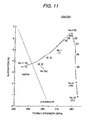
- FIG. 11 is a graph showing the relationship between tensile strength and elongation of the Mg based alloy when the Sn content is varied to the 12% Al- 3% Zn alloy. As shown in the graph, although the strength and the elongation are increased up to the Sn content of 5 %, the strength is increased but the elongation is decreased when the Sn content exceeds 5 %. However, the elongation is as high as 0.5 % even at the Sn content of 11 %.
- FIG. 12 is a graph showing the relationship between tensile strength and elongation of the Mg based alloy when the Al content is varied to the 3% Zn- 5% Sn alloy. As shown in the graph, it can be understood that the tensile strength having a value higher than 275 MPa can be obtained by increasing the Al content to 12 %, and the elongation having a value higher than 0.5 % can be also obtained when the Al content is less than 20.5 %. It is also preferable that in this graph, the values are set higher than the values calculated by the above-described relationship expressed by the elongation ratio (y) and the tensile strength (x).
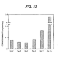
- FIG. 13 is a graph showing the corrosion rate of injection molded articles made of the present embodiments of alloys No. 2, 5, 6, 7 and the comparative alloys No. 11, 15 by a salt water spray test (splaying 5 % NaCl aqueous solution for 360 hours) at 20°C. From the graph, it can be understood that all the alloys of the present embodiment have better corrosion resistance below corrosion mass loss of 0.1 (mg/cm 2 ⁇ day) compared to that of AZ91D alloy (No. 11). Further, it can be also understood that the corrosion resistance is more improved as the Al content is higher. Further, as it is clear from the fact that the alloy No.2 added with Mn shows better corrosion resistance compared to that of the comparative alloy No. 15 not added with Mn, addition of a very small amount of Mn substantially increase the corrosion resistance. Further, as shown by the alloys No. 5 and 7, it can be understood that high corrosion resistance can be obtained by increasing the Al content.
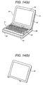
- FIG. 14 is a perspective view showing a notebock-size personal computer.
- a keyboard 22 for operating input means and a switch board unit 23 containing light-emitting diodes (LEDs) for indicators and a main switch.
- the exterior of the main body 21 is composed of a main body upper case 26 and main body bottom case 27.
- the exterior of a display portion 24 is composed of a liquid crystal display (LCD) case 41 and an LCD front 42. In the LCD front 42, a display window is opened so that the display portion of the liquid crystal screen 25.
- LCD liquid crystal display
- the LCD front 42 was molded using the alloy No. 2 by an injection molding machine of 650 t mold clamping force in order to make the weight light and to improve the stiffness and the heat dissipation.
- the injection speed was 3 m/sec
- molten alloy temperature was 580 °C
- metal mold temperature was 200 °C.
- the dimension of the molded article was 230 mm ⁇ 180 mm ⁇ 4 mm, and average thickness of 0.7 mm.
- the molded article obtained through such a way could be formed in a good dimensional accuracy without surface defects and with good yield.
- the bottom case was fabricated.
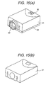
- FIG. 15 is a perspective view showing a mobile type liquid crystal projector.
- a main body is composed of a switch board unit 32 containing LEDs for indicators and a main switch and a projection lens 33, and the exterior is composed of a main body upper case 31 and a main body bottom case 34.
- the main body upper case 31 was casted using the alloy No. 2 by a hot chamber die-cast machine of 600 t mold clamping force.
- the molding condition was injection speed of 2.5 m/sec, molten alloy temperature of 600 °C and metal mold temperature of 200 °C .
- the dimension of the molded article was 248 mm ⁇ 330 mm ⁇ 100 mm, and average thickness of 1.5 mm. Even though the component was comparatively large, a good molded article could be formed without filling defects in a thin wall portion nor occurrence of surface defects
- FIG. 16 is a perspective view showing a home electric vacuum cleaner having an impeller using the Mg based alloy in accordance with the present invention.
- the reference character 51 is a vacuum cleaner main body which contains a control circuit and an electric drive fan and so on
- the reference character 52 is a hose connected to a suction nozzle portion of the vacuum cleaner main body 51
- the reference character 53 is a hose grip portion
- the reference character 54 is an extension pipe connected to an end (the hose grip portion 53) of the hose
- the reference character 55 is a nozzle body connected to the extension pipe 54
- the reference character 56 is a switch operating portion arranged in the hose grip portion 53
- the reference character 57 is a first infrared light emitting portion arranged in the hose grip portion 53
- the reference character 58 is a second infrared light emitting portion arranged in the hose grip portion 53
- the reference character 59 is an infrared light receiving portion arranged on the upper surface of the vacuum cleaner main body.
- FIG. 17 is an exploded perspective view showing the impeller.
- an injection molding method was employed in the present embodiment.
- a light metal raw material formed in pellets is used similarly to the injection molding method, and kneaded and melted directly inside an injection molding machine without using any melting furnace or the like, and injected into a metal mold to obtain a molded article.
- the front plate 61, the rear plate 62 and the blades 63 integrated in one piece are individually formed in one piece using the magnesium based alloy shown in Embodiment 1.
- Solder material layers are provided over all the surfaces of the front plate 61 and the rear plate 62, and the blades 63 are joined with the solder material.
- the reference character 64 is a suction port.
- the impeller can be obtained by a mixed molten alloy of liquid phase and solid phase using the injection molding machine shown in FIG. 1.
- the impeller can be made light in weight without filling defects even though the wall thickness is as thin as 0.7 mm, and the air flow resistance can be reduced. Therefore, the rotating speed of 45000 to 50000 rpm can be attained at 1 kW consumed electric power, and the suction power can be attained above 550 W.
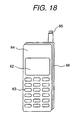
- Figure 18 shows a perspective view of a portable telephone apparatus to which a magnesium-based alloy disclosed in the embodiment 1 in the present invention is applied.
- the apparatus is comprised of a cover (64) that includes a number display part (62) and a plurality of keys (63), a retractable antenna (65), and a case (66).
- the cover (64) and the case (66) were injection-molded out of the alloy No.2 for reduce weight, and improving stiffness, heat dissipation, and electromagnetic shielding properties using an injection molding apparatus having mold clamping force of 75 ton.
- the injection speed was 1 m/s and the temperature of the molten metal was 580°C.
- the dimensions of the molded product were 125 mm by 38 mm by 8 mm and average wall thickness was 0.5 mm.
- This alloy has not caused any filling-defect and surface-defect with acceptable yield in molding process even in a thin wall product like this embodiment.
- a front cabinet of a 21-inch type television set, a steering wheel core of a vehicle, a case body of a video-camera, a rid of an MD player and a case body of a compact camera are manufactured by a mixed molten alloy of liquid phase and solid phase using the injection molding machine shown in FIG. 1. In these cases, good molding crystals can be obtained without filling defects even though the wall thickness is as thin as 0.7 mm.
- Oxide films having 0.1 to 3 ⁇ m were formed on the surfaces of the various kinds of the products described in Embodiments 3 to 6 using the Mg based alloys in accordance with the present invention by immersing the products into aqueous solutions of 1M-Na 2 MoO 4 and 1M-Na 2 SO 4 -0.5M ⁇ NaF (adjusting to pH 3.0 with H 2 SO 4 ) at 60 °C for 180 seconds, respectively.
- the surface of the product is colored, and the thickness of the film can be estimated from the tone of the color. The color is changed from light brown to dark blown, and further to black depending on the processing time.
- the obtained film showed good corrosion resistance, and had such an inert electric potential that the natural immersion electric potential 30 minutes after immersing into an aqueous solution of 0.01M-Na 2 B 4 O 7 (pH 9.18) was higher than -1500 mV. Further, the oxide film was suitable as a based for coating with paint.
- a water repellent fluoride film was further coated on the oxide film by being immersed into a solution dissolving perfluoro-hexane for 24 hours and then by being heated at 150 °C for 10 minutes.
- the organic film had such a high water repellence that the contact angle with water was 120 to 130 degrees, and accordingly the durability could be further improved.
- an Mg based alloy which is low in melting point, good in fluidity at molding, and good in mechanical property due to uniform and fine structure. Further, by reducing number of surface defects by improving the fluidity and by improving the dimensional accuracy by low temperature molding, the molding yield can be substantially improved. Furthermore, by reducing load to the metal members and the heat resistant members such as the mold and the cylinder of the injection molding machine, the lifetime of these members can be extended, and accordingly the production efficiency of the magnesium based alloy parts can be improved.
- the oxide film containing heavy metals having plural valences and enriched with Al in the based material on the surface of the Al containing Mg alloy can serve as a paint based having good corrosion resistance. Further, the film described above can be fabricated without using any material harmful for the environment.
Landscapes
- Chemical & Material Sciences (AREA)
- Engineering & Computer Science (AREA)
- Materials Engineering (AREA)
- Mechanical Engineering (AREA)
- Metallurgy (AREA)
- Organic Chemistry (AREA)
- Injection Moulding Of Plastics Or The Like (AREA)
- Body Structure For Vehicles (AREA)
- Electric Double-Layer Capacitors Or The Like (AREA)
Description
- The present invention relates to a novel Mg based alloy and a novel Mg casting alloy capable of mass producing OA parts, car parts, electric appliance parts and so on through die casting, injection molding or the like, and relates to articles mold-cast using the alloy.
- The casting Mg alloys practically used in present time are as follows:
- (1) AZ, AM alloys (Mg-Al-(Zn)-Mn system, for example, ASTM: AZ91D);
- (2) AS alloy (Mg-Al-Si-Mn system, for example, ASTM: AS41); and
- (3) AE, QE, WE alloys (an alloy group containing one or more kinds of REM, Ag, Y).
-
- The alloy (1) is most commonly used as the die casting and the injection molding Mg alloy, and particularly the AZ91D is good in die-castability and in corrosion resistance and widely applied to car parts and electric appliance parts. The alloys (2), (3) are alloys improving the mechanical properties such as the creep property and the high temperature strength. As the prior art in regard to these alloys, various kinds of alloys are disclosed in the following patent gazettes.
- For example, Japanese Patent Application Laid-Open No.6-330216 discloses an Mg based alloy containing Ca, Si, Al, Zn and Mn, Japanese Patent Application Laid-Open No.9-104942 discloses an Mg based alloy containing 5 to 10 of Al, 0.2 to 1 of Si and 0.05 to 0.5 of Cu, and Japanese Patent Application Laid-Open No.10-147830 discloses an Mg based alloy containing 1 to 6 of Gd and 6 to 12 of Y.
- US-A-2 000 115 discloses a magnesium-based alloy having an improved hot working performance, containing 0.5 to 10.0 % Al, 0.1 to 12 % Sn, 0.1 to 1.0 % Mn, and Zn and/or Cd in an amount of 0.1 to 5.0 %, the balance being Mg.
- GB-A-2 058 837 describes a magnesium alloy containing 1 to 9 % Al, 0 to 4 % Zn, 0.1 to 5 % Sn, 0 to 1 % Mn, which is used as an anode in electric cells.
- In US-A-1 942 041 a magnesium-based alloy with an improved hot working performance, containing 0.1 to 12.0 % Sn, 0.5 to 6.0 % Al, 0.1 to 1.0 % Mn is described.
- In GB-A-265 299 a description of an Mg-based alloy which is used as a material for cocks or valves is given.
- GB-A-1 291 553 describes an Mg-based alloy having 5.5 to 10 % Al, 0.3 to 2 % Zn and 0.1 to 0.4 % Sb or Sn for preventing hot crack during die casting of the alloy.
- US-A-3 653 880 describes a magnesium based cast alloy having a little tendency to hot-crack, with a composition of 3 to 10 % Al, 0.3 to 2 % Zn and 0.1 to 0.4 % Sb or Sn.
- DE-A-19 34 617 discloses a magnesium alloy containing 3-30% Al, 0.3-2% Zn, 0.05-0.5 Bi or Sn, up to 0.5 % Mn, up to 0.5 % Si, up to 0.5 Cu.
- With growing needs of thin thickness and high precision of parts in order to reduce in weight and size of potable devices, high fluidity alloys have been required. The alloy (1) of AZ91D described above is comparatively high in the fluidity, but the molding yield in injection molding is not always sufficiently high.
- The alloy groups (2), (3) are prior to AZ91D in the mechanical properties such as creep property, strength at high temperature. However, because of the bad fluidity, the alloy groups (2), (3) are apt to cause casting cracks in the molding method of high speed cooling such as the injection molding method and are bad in castability.
- The fluidity may be improved by raising the temperature of molten alloy. However, raising of the molten alloy temperature has problems in oxidation of the molten alloy and in shortening of durable lifetime of the production machines. Therefore, it is necessary to improve the fluidity by the other method.
- It is known that the solidification structure of AZ91D becomes dendritic when it is cooled in a comparatively slow speed such as at ingot casting. As described above, the alloy is designed by placing special emphasis on the molten fluidity, and in regard to the properties after solidification, the alloy is designed so that the various kinds of properties such as the mechanical properties are optimized on the premise that the structure of AZ91D becomes dendritic.
- However, in the cases of die casting and injection molding to which the alloy is widely applied, it is known that the structure after solidification becomes the cellular structure not the dendritic structure because the cooling rate is very fast. Therefore, it is required to change the designing method of the conventional alloying composition.
- An object of the present invention is to provide a high strength Mg based alloy and a Mg based casting alloy having a good fluidity and a good mechanical property, and a cast article using the alloy.
- As a result of various kinds of studies in order to solve the problems described above, it is found that the melting point of the alloy is lowered and the fluidity is improved by adding appropriate amounts of Al, Sn and Zn to a magnesium alloy, and the present invention, as defined in
claim 1, is established. - Preferably, the alloy according to the invention has a crystal size of 10 to 300 µm.
- A preferred embodiment of the high strength Mg based alloy, contain 18 to 20 % of Al by weight; 0.1 to 5 % of Zn; 0.1 to 10 % of Sn; and less than 1.5 % of Mn, the remainder consisting of Mg and unavoidable impurities, and has a tensile strength (x) at 20 °C larger than 240 MPa; and an elongation ratio (y) larger than 0.5 % and at the same time larger than a value calculated by y = -0.295x + 78.
- According to claim 4 a high strength Mg based alloy, contains 12 to 15 % of Al by weight; 0.1 to 5 % of Zn; 1 to 10 % of Sn; 0.1 to 0.5 % of Mn, and the remainder contains Mg more than 75 %.
- A Mg based casting alloy according to the invention may contain 12 to 15 % of Al by weight; 0.5 to 3 % of Zn; 1.5 to 4.5 % of Sn; 0.05 to 0.5 % of Mn.
- The present invention provides a die cast article or injection molding article, which is casted using a molten metal of any one of the alloys described above.
- The present invention provides a thixotropic mold article, which is molded using a molten metal of a mixture of liquid phase and solid phase of any one of the alloys described above.
- In detail, it is preferable that the magnesium based alloys described above are formed in desirable shapes through die casting by injection molding.
- The magnesium alloys in accordance with the present invention are improved in the fluidity due to lowering of the melting point particularly by adding a small amount of Sn to the Mg based alloy containing Al, and accordingly members having less surface defects can be obtained. Further, since low temperature molding can be performed and accordingly the contraction at solidifying is small, members having a high dimensional accuracy can be obtained. Therefore, the molding yield can be largely improved.
- Further, since the load to the machines, for example, the cylinder of an injection molding machine or the like is decreased, the durable lifetime of the heat resistant materials can be lengthened.
- Furthermore, the magnesium alloys in accordance with the present invention are good in mechanical property and corrosion resistance because of the homogeneous and fine microstructure.
- For the purpose of solid-solution hardening, precipitation hardening and improvement of fluidity, the element Al is added above 12 %. However, an excessive addition exceeding 20 % of the element Al produces a large grain Mg-Al intermetallic compound to substantially decrease the elongation of the molded products. Further, in the casting method having a high cooling rate such as the die casting or the injection molding, the solidified structure becomes finer as the content of Al is increased, and the Mg-Al intermetallic compound does not grow large-sized, but is finely distributed in the crystal grain boundaries. This effect becomes obvious particularly when Sn is added together. In order to make the elongation above 3.5 % and the tensile strength above 265 MPa, it is preferable to add 12 to 17 % of Al.
- Further, the element Al in the magnesium alloy in accordance with the present invention is solved in the α-Mg phase,and reduce the melting point of the alloy. Further, the element Al is solid-solved in the α-Mg phase and crystallizes the Mg-Al intermetallic compound,with theresult that the strength at room temperature of the alloy is improved. Furthermore, the element Al suppresses oxidation of the molten alloy, and improves fluidity of the molten alloy. In order to attain these effects, the Al content is above 12 %, and preferably above 15 %.
- The element Sn is solved in the α-Mg phase ,and reduce the melting point of the alloy with a small amount of nearly 0.1 %, particularly more than 0.5 %. Further, the element Sn is solved in the α-Mg phase and crystallizes the Mg-Sn intermetallic compound,as a result the strength at room temperature is improved. Furthermore, the effect of Sn on lowering the melting point becomes obvious particularly when Al and Zn are added together, but the effect is almost saturated when the Sn content becomes 5 %. Further, when the Sn content exceeds 15 %, the elongation is largely decreased, and the density of the alloy becomes large,and lose the advantage of lightness of the magnesium alloy. Particularly, the Sn content needs to be lower than 10 % in order to keep the elongation above 3.5 %, and the Sn content needs to be preferably lower than 8 % in order to keep the elongation above 4 %. When the Sn content is 1 to 7 %, it is possible to obtain an alloy having both of high strength and high elongation.
- The element Zn is added above 0.1 % in order to improve the strength at room temperature and the castability. However, when the Zn content exceeds 10 %, casting cracks are apt to occur. It is preferable that the Zn content is within a range of 0.1 to 5 %,preferably 1 to 5% in which the strength is high and the casting cracks do not occur.
- The element Mn improve the corrosion resistance. This is because Mn forms a intermetallic compound with Al ,and fix Fe in the intermetallic compound, the element Fe being contained in the alloy as an impurity deteriorate the corrosion resistance. When the Mn content exceeds 1 %, the Al-Mn group intermetallic compound excessively deposited and cause an evil effect on the mechanical property, the upper limit of Mn content is set to 1 %. Particularly, for the corrosion resistance, Mn content is effective above 0.05 %, and preferably 0.1 to 0.5 %.
- The alloy in accordance with the present invention further contains at least one element selected from the group consisting of Ca, Si and rear-earth elements, the content of the one kind or in total being less than 5 %; and at least one element selected from the group consisting of Sr and Sb, the content of the one kind or in total being less than 1 %. The elements Ca and Si and rear-earth elements are effective to lower the melting point because these elements form eutectic groups with Mg. However, since addition of these elements deteriorates the casting property, the upper limit of the content is 5 %. Particularly, it is preferable that the content is above 0.1 % and the upper limit is set to 3 %.
- The elements Sr and Sb make the metallic structure fine,and to improve the mechanical properties. The effect of elements Sr and Sb is increased when the element Si or Ca is added together. The effect of elements Sr and Sb is increased as the content is increased, but the effect is saturated when the content exceeds 1 %. Therefore, the upper limit is set to 1 %. Particularly, it is preferable that the content is above 0.03 %, and the upper limit is set to 0.5 %.
- The Mg based alloy in accordance with the present invention is characterized that the surface is covered with an oxide film which contains Mg of 15 to 35 % by atoms; preferably 20 to 30 %, and Mo of 5 to 20 %. The Mg based alloy in accordance with the present invention is characterized that the surface is covered with an oxide film which contains Mg of 15 to 35 % by atoms; Mo of 5 to 20; and metallic Al of less than 30 %, preferably 10 to 25 %. The Mg based alloy in accordance with the present invention is characterized that the surface is covered with an oxide film which contains Mg of 15 to 35 % by atoms; Mo of 5 to 20; oxide Al of less than 15 %; and metallic Al of less than 15 %, preferably 4 to 12 %. The Mg based alloy in accordance with the present invention is characterized that the surface is covered with an inert oxide film of which a natural immersion electric potential 30 minutes after immersing into an aqueous solution of 0.01 mol Na2B4O7, pH 9.2, 25 °C is higher than -1500 mV, preferably higher than - 1400 mV. The Mg based alloy in accordance with the present invention is characterized that the surface is covered with an oxide film of which a natural immersion electric potential 15 minutes after immersing into an aqueous solution of 0.01 mol Na2SO4, 25 °C is higher than -1500 mV, preferably higher than -1400 mV. Further, the Mg based alloy in accordance with the present invention is characterized that the surface is covered with the above-described oxide film or a specified oxide film, and a water repellent organic film containing fluoride is further coated on the oxide film.
-
- FIG. 1 is a cross-sectional view showing the construction of an injection molding machine used in the present embodiment.
- FIG. 2 is a microscopic photograph showing the
metallic structure of a magnesium based alloy ingot
fabricated in the
embodiment 1. - FIG. 3 is a graph showing the relationship between Sn content and melting point.
- FIG. 4 is a diagram that shows the relationship between the cylinder temperature and fluidity lengths for both the magnesium-based alloy No.2 in the present invention and an alloy AZ91D in a prior art.
- FIG. 5 is a graph showing the relationship between Sn content and Vickers hardness.
- FIG. 6 is a graph showing the relationship between Sn content and tensile strength.
- FIG. 7 is a graph showing the relationship between Sn content and elongation ratio.
- FIG. 8 is a graph showing the relationship between Al content and tensile strength.
- FIG. 9 is a graph showing the relationship between Al content and elongation.
- FIG. 10 is a SEM photograph showing the metallic
structure of a magnesium based alloy ingot fabricated in
the
embodiment 2. - FIG. 11 is a graph showing the relationship between elongation and tensile strength.
- FIG. 12 is a graph showing the relationship between elongation and tensile strength.
- FIG. 13 is a graph showing the salt spray test result for varous Mg based alloys.
- FIG. 14 is a perspective view showing a note-shaped personal computer.
- FIG. 15 is a perspective view showing a mobile type liquid crystal projector.
- FIG. 16 is a perspective view showing a home electric vacuum cleaner.
- FIG. 17 is a perspective view showing an impeller.
- FIG. 18 shows a perspective view of a portable
telephone apparatus to which a magnesium-based alloy
disclosed in the
embodiment 1 in the present invention is applied. -
- A magnesium chloride type flux was applied on the inner surface of a melting pot made of casting iron pre-heated in an electric furnace, and raw materials were put into the melting pot so as to form an alloy having a composition (weight %) shown in Table 1 to be melted. After stirring the molten metal at 750 °C and removing slag, the molten metal was cast in a metal mold of 50 mm × 50 mm × 300 mm pre-heated to 150 °C to fabricate a Mg alloy ingot. During melting work, in order to preventing burning the flux was sprinkled on the molten alloy surface, if necessary.Mm is a mischmetal (La50wt%-Ce50wt% alloy).
- FIG. 2 shows a typical metallic structure of an alloy obtained through the method as described above. Mg-Al compound phase (white portions) are crystallized in a network shape in the α-phase grain boundary, and Mg-Sn compound phase (black portions) are crystallized between the network of the Mg-Al compound phase.
- FIG. 3 shows measured results of melting points of the alloys, particularly the relationship between the melting point and Sn content for the alloys No. 1 to 3 and 11 to 13. The alloy melting point is decreased as the Sn content is increased, and the effect of Sn addition on the melting point is saturated when the its content exceeds 10 Wt%. However, it can be understood that the melting point of the alloy No. 12 containing Al and Zn contents less than the specified values of the present invention is small in the melting point fall from AZ91D alloy (No. 11). Further, as shown in the figure, the melting point is steeply decreased as the Sn content is increased up to the Sn content of 2 %, but mildly decrease where the Sn content is above 2 %. Further, by making the Sn content above 0.5 %, The melting point is lower than that596 °C of AZ91D.
- A magnesium chloride type flux was applied on the inner surface of a melting pot made of casting iron pre-heated in an electric furnace, and raw materials were put into the melting pot so as to form an alloy having a composition (weight %) shown in Table 1 to be melted. After stirring the molten metal at 750 °C and removing slag, the molten metal was cast in a metal mold of 50 mm × 50 mm × 300 mm pre-heated to 150 °C to fabricate a Mg alloy ingot. During melting work, in order to preventing burning the flux was sprinkled on the molten alloy surface, if necessary. An alloy chip of 2 mm to 10 mm diameter was fabricated by milling the ingot obtained through the method as described above, and used as a raw material for injection molding. A machine having a mold clamping force of 75 t was used for the injection molding to form an injection molded piece of 120 mm × 50 mm × 1 mm thickness. The molding condition was as follows. A Mm (mischmetal) indicates an alloy containg 50 wt % La and 50 wt % Ce.
- Injection speed: 1.6 m/s
- Injection pressure: 800 kg/cm2
- Molten metal temperature: alloy melting point + 20 °C
- Mold temperature: 150 °C
-
- Strength evaluation tests (hardness, tensile strength, elongation) were conducted by obtaining the following test pieces from the molded pieces obtained as described above.
- Test piece: 1 mm thickness, 12 mm gage length, 16 mm length and 10 mm width of parallel part.
- Tensile test: Using an Instron testing machine, measurement was performed under the condition of 0.3/min strain speed and at 25 °C.
- The test pieces No. 1 to 10 and 13 are samples each within the composition range of the embodiment of the present invention, and the test pieces No. 11, 12, 14 and 15 are comparative examples out of the composition range of the embodiment of the present invention (the test piece No. 11 is AZ91D standard alloy).
Alloy No. Al Zn Sn Mn Others Mg 1 12 3 1 0.2 - bal. 2 12 3 5 0.2 - bal. 3 12 3 10 0.2 - bal. 4 12 5 5 0.2 - bal. 5 15 3 5 0.2 - bal. 6 18 3 5 0.2 - bal. 7 20 3 5 0.2 - bal. 8 12 1 3 0.2 Si: 1, Sr: 0.05 bal. 9 12 1 3 0.2 Ca: 2, Sb: 0.05 bal. 10 12 1 3 0.2 Mm: 2 bal. 11 8.9 0.76 - 0.24 - bal. 12 11 0 1 0.2 - bal. 13 12 3 11 0.2 - bal. 14 21 3 5 0.2 - bal. 15 12 3 5 - - bal. - FIG. 1 is a cross-sectional view showing the main portion of the injection molding machine used in the present embodiment.
- An alloy
raw material 1 for injection molding is put into ahopper 2 to be supplied into acylinder 4. The raw material is kneaded and mixed in thecylinder 4 while being transferred toward anozzle 6 by arotating screw 5, and at the same time heated by acylinder heater 7. The alloy raw material is injection molded under a melted state where the heated temperature is higher than the liquid-phase line temperature, or under a semi-melted state where a solid phase having a temperature lower than the liquid-phase line temperature and a liquid phase are mixed. The melted state or semi-melted statemolten metal 10 of the raw alloy material transferred to the front portion of thescrew 5 is filled into ametal mold 9 though thenozzle 6 by moving the screw forward using a highspeed injection mechanism 8. The pressure in the metal mold is kept until the molten metal is solidified, and after being solidified themetal mold 9 is opened to take out the molded article. Referring to the figure, thescrew 5 has aspiral blade 13 on a cylindrical solid basedbody 14, and the alloyraw material 1 is heated up to a high temperature to be made the melted state or the semi-melted state depending on the temperature of theheater 7 while being kneaded with theblade 13 by rotation of thescrew 5. Thereference character 12 is a backflow preventing ring for themolten metal 10. - The alloy
raw material 1 used in the present embodiment is prepared by melting an alloy of each of the compositions under a non-oxidized atmosphere, and then by cutting the formed alloy into chips smaller than 10 mm to form grains of the raw material. - Figure 4 is a diagram that shows the relationship between the injection temperature and fluidity lengths for both the magnesium-based alloy No.2 in the present invention, an alloy AZ91D in a prior art. The cylinder temperature is the temperature at which alloys were molded for their fluidity length verification. The fluidity length of an alloy is the length for such sound portion in an injection-molded alloy that has no surface-defects like crack.
- The fluidity length was verified using a fluidity length verification metallic mold having a width of 10 mm, a thickness of 1 mm, and an overall length of 380 mm, intowhich each alloy to be verified was injection-molded by an injection molding apparatus shown in Figure 1 keeping the verification metallic mold constantly at 200°C.
- As shown in Figure 4, it is evident that the alloy in the present invention has higher fluidity length performance than alloy AZ91D at any temperature in our investigation.
- In contrast to that the fluidity lengths of alloys in a prior art reaches saturation of about 300 mm at a
temperature 600°C, the alloy No.12 that includes 3 % zinc spread its fluidity length to about 350 mm at 570°C and another alloy in the present invention that includes 1 % zinc also spreads to about 350 mm at 580°C. - FIG. 5 to FIG. 7 are graphs showing the relationships between Sn content and test results of hardness and tensile strength of the injection molded article made of each of the alloys shown in Table 1. As shown in the graphs, by adding Sn by 1 %, both of the hardness and the tensile strength become above Hv 110 in hardness and above 269 MPa in tensile strength, respectively. On the other hand, the elongation ratio is improved until the Sn content is increased up to 5 wt%, but is decreased when the Sn content exceeds 5 %, and is steeply decreased to a value before adding Sn when the Sn content exceeds 9 %.
- FIG. 8 and FIG. 9 are graphs showing results of tensile test when the Al content is varied on the basis of the alloy No. 2 (Mg-12Al-3Zn-5Sn). As shown in the graphs, the tensile strength is improved with increasing the Al content, and the tensile above 279 MPa can be obtained up to 12 % of Al content. In regard to the elongation ratio, the elongation ratio above 1.9 % can be obtained up to 20 % of Al content. However, when the Al content exceeds 20 %, the elongation ratio is extremely decreased to a value smaller than 1 %, which is impractical.
- As the contents of Al, Zn, Sn in the magnesium alloy are increased, (Mg-Al group, Mg-Sn group) crystallized in the α-phase grain boundaries are increased. Increase in the amount of the generally causes to lower the elongation. However, addition of Al, Zn, Sn also has an effect to fine the α-phase, and accordingly the relative ratio of the α-phase grain boundary volume to the intermetallic compound amount is not largely changed even if the amount of the intermetallic compound is increased. Therefore, it can be considered that large decrease of elongation can be suppressed. However, it is considered that the fining effect is saturated and the elongation is steeply decreased at values near the Sn and Al contents of 10 wt% and 20 wt%, respectively.
- FIG. 10 shows the photograph of the structure of the injection molded article made of the alloy No.2. The α-phase grains having size of nearly 1 to 20 µm, mainly less than 5 µm and the Mg-Al compound phase crystallized in network shape in the grain boundaries are observed. White small nodules are the Mg-Sn compound phase, and it can be understood from this photograph that the solidification structure is refined, and the Mg-Al and the Mg-Sn compound phase are uniformly distributed.
- In the case where among the magnesium alloys described above, the embodiments of the alloys No. 1 to 3 in accordance with the present invention are injection molded by setting the molten alloy temperature to the same value (620 °C), surface defects of the molded articles of the alloys No. 1 to 3 are substantially decreased compared to those of the molded article of AZ91D alloy. The reason is that the difference between the molten alloy temperature and the melting point becomes larger by the amount of decreasing the melting point, and accordingly the fluidity is improved.
- Further, in the case where molding was performed by setting the molten alloy temperature at injection molding to a temperature lower than the melting point of the alloy by 10 °C, that is, in the case where injection molding was performed under the semi-solid state that the solid phase and the liquid phase were mixed, the dimensional accuracy of the molded article made of each of the alloys was better than that of AZ91D alloy.
- FIG. 11 is a graph showing the relationship between tensile strength and elongation of the Mg based alloy when the Sn content is varied to the 12% Al- 3% Zn alloy. As shown in the graph, although the strength and the elongation are increased up to the Sn content of 5 %, the strength is increased but the elongation is decreased when the Sn content exceeds 5 %. However, the elongation is as high as 0.5 % even at the Sn content of 11 %.
- The straight line in the graph is expressed by the elongation (%) (y) and the tensile strength (MPa) (x), the present embodiment has the elongation higher than the value calculated by y = -0.295x + 78. Further, it is preferable that the tensile strength and the elongation are higher than values calculated by the relationships y = -0.295x + 82, 85 or 87.
- FIG. 12 is a graph showing the relationship between tensile strength and elongation of the Mg based alloy when the Al content is varied to the 3% Zn- 5% Sn alloy. As shown in the graph, it can be understood that the tensile strength having a value higher than 275 MPa can be obtained by increasing the Al content to 12 %, and the elongation having a value higher than 0.5 % can be also obtained when the Al content is less than 20.5 %. It is also preferable that in this graph, the values are set higher than the values calculated by the above-described relationship expressed by the elongation ratio (y) and the tensile strength (x).
- FIG. 13 is a graph showing the corrosion rate of injection molded articles made of the present embodiments of alloys No. 2, 5, 6, 7 and the comparative alloys No. 11, 15 by a salt water spray test (splaying 5 % NaCl aqueous solution for 360 hours) at 20°C. From the graph, it can be understood that all the alloys of the present embodiment have better corrosion resistance below corrosion mass loss of 0.1 (mg/cm2 · day) compared to that of AZ91D alloy (No. 11). Further, it can be also understood that the corrosion resistance is more improved as the Al content is higher. Further, as it is clear from the fact that the alloy No.2 added with Mn shows better corrosion resistance compared to that of the comparative alloy No. 15 not added with Mn, addition of a very small amount of Mn substantially increase the corrosion resistance. Further, as shown by the alloys No. 5 and 7, it can be understood that high corrosion resistance can be obtained by increasing the Al content.
- FIG. 14 is a perspective view showing a notebock-size personal computer. In a
main body 21, there are arranged akeyboard 22 for operating input means and aswitch board unit 23 containing light-emitting diodes (LEDs) for indicators and a main switch. The exterior of themain body 21 is composed of a main bodyupper case 26 and mainbody bottom case 27. The exterior of adisplay portion 24 is composed of a liquid crystal display (LCD)case 41 and anLCD front 42. In theLCD front 42, a display window is opened so that the display portion of theliquid crystal screen 25. - Among these components, the
LCD front 42 was molded using the alloy No. 2 by an injection molding machine of 650 t mold clamping force in order to make the weight light and to improve the stiffness and the heat dissipation. The injection speed was 3 m/sec, molten alloy temperature was 580 °C and metal mold temperature was 200 °C. The dimension of the molded article was 230 mm × 180 mm × 4 mm, and average thickness of 0.7 mm. The molded article obtained through such a way could be formed in a good dimensional accuracy without surface defects and with good yield. Similarly, the bottom case was fabricated. - FIG. 15 is a perspective view showing a mobile type liquid crystal projector.
- A main body is composed of a
switch board unit 32 containing LEDs for indicators and a main switch and aprojection lens 33, and the exterior is composed of a main bodyupper case 31 and a mainbody bottom case 34. - Among these components, the main body
upper case 31 was casted using the alloy No. 2 by a hot chamber die-cast machine of 600 t mold clamping force. The molding condition was injection speed of 2.5 m/sec, molten alloy temperature of 600 °C and metal mold temperature of 200 °C . The dimension of the molded article was 248 mm× 330 mm× 100 mm, and average thickness of 1.5 mm. Even though the component was comparatively large, a good molded article could be formed without filling defects in a thin wall portion nor occurrence of surface defects - FIG. 16 is a perspective view showing a home electric vacuum cleaner having an impeller using the Mg based alloy in accordance with the present invention.
- Referring to FIG. 16, the
reference character 51 is a vacuum cleaner main body which contains a control circuit and an electric drive fan and so on, thereference character 52 is a hose connected to a suction nozzle portion of the vacuum cleanermain body 51, thereference character 53 is a hose grip portion, thereference character 54 is an extension pipe connected to an end (the hose grip portion 53) of the hose, thereference character 55 is a nozzle body connected to theextension pipe 54, thereference character 56 is a switch operating portion arranged in thehose grip portion 53, thereference character 57 is a first infrared light emitting portion arranged in thehose grip portion 53, thereference character 58 is a second infrared light emitting portion arranged in thehose grip portion 53, and thereference character 59 is an infrared light receiving portion arranged on the upper surface of the vacuum cleaner main body. - FIG. 17 is an exploded perspective view showing the impeller.
- As a molding method of integrating a
front plate 61, arear plate 62 andblades 63 in one piece, an injection molding method was employed in the present embodiment. In this method, a light metal raw material formed in pellets is used similarly to the injection molding method, and kneaded and melted directly inside an injection molding machine without using any melting furnace or the like, and injected into a metal mold to obtain a molded article. In the present embodiment, thefront plate 61, therear plate 62 and theblades 63 integrated in one piece are individually formed in one piece using the magnesium based alloy shown inEmbodiment 1. Solder material layers are provided over all the surfaces of thefront plate 61 and therear plate 62, and theblades 63 are joined with the solder material. Thereference character 64 is a suction port. In the present embodiment, the impeller can be obtained by a mixed molten alloy of liquid phase and solid phase using the injection molding machine shown in FIG. 1. - According to the present embodiment, the impeller can be made light in weight without filling defects even though the wall thickness is as thin as 0.7 mm, and the air flow resistance can be reduced. Therefore, the rotating speed of 45000 to 50000 rpm can be attained at 1 kW consumed electric power, and the suction power can be attained above 550 W.
- Figure 18 shows a perspective view of a portable telephone apparatus to which a magnesium-based alloy disclosed in the
embodiment 1 in the present invention is applied. As illustrated in Figure 18, the apparatus is comprised of a cover (64) that includes a number display part (62) and a plurality of keys (63), a retractable antenna (65), and a case (66). - Among these parts, the cover (64) and the case (66) were injection-molded out of the alloy No.2 for reduce weight, and improving stiffness, heat dissipation, and electromagnetic shielding properties using an injection molding apparatus having mold clamping force of 75 ton. The injection speed was 1 m/s and the temperature of the molten metal was 580°C. The dimensions of the molded product were 125 mm by 38 mm by 8 mm and average wall thickness was 0.5 mm. This alloy has not caused any filling-defect and surface-defect with acceptable yield in molding process even in a thin wall product like this embodiment.
- A front cabinet of a 21-inch type television set, a steering wheel core of a vehicle, a case body of a video-camera, a rid of an MD player and a case body of a compact camera are manufactured by a mixed molten alloy of liquid phase and solid phase using the injection molding machine shown in FIG. 1. In these cases, good molding crystals can be obtained without filling defects even though the wall thickness is as thin as 0.7 mm.
- Oxide films having 0.1 to 3 µm were formed on the surfaces of the various kinds of the products described in
Embodiments 3 to 6 using the Mg based alloys in accordance with the present invention by immersing the products into aqueous solutions of 1M-Na2MoO4 and 1M-Na2SO4-0.5M · NaF (adjusting to pH 3.0 with H2SO4) at 60 °C for 180 seconds, respectively. The surface of the product is colored, and the thickness of the film can be estimated from the tone of the color. The color is changed from light brown to dark blown, and further to black depending on the processing time. The obtained film showed good corrosion resistance, and had such an inert electric potential that the natural immersion electric potential 30 minutes after immersing into an aqueous solution of 0.01M-Na2B4O7 (pH 9.18) was higher than -1500 mV. Further, the oxide film was suitable as a based for coating with paint. - A water repellent fluoride film was further coated on the oxide film by being immersed into a solution dissolving perfluoro-hexane for 24 hours and then by being heated at 150 °C for 10 minutes. The organic film had such a high water repellence that the contact angle with water was 120 to 130 degrees, and accordingly the durability could be further improved.
- According to the present invention, it is possible to obtain an Mg based alloy which is low in melting point, good in fluidity at molding, and good in mechanical property due to uniform and fine structure. Further, by reducing number of surface defects by improving the fluidity and by improving the dimensional accuracy by low temperature molding, the molding yield can be substantially improved. Furthermore, by reducing load to the metal members and the heat resistant members such as the mold and the cylinder of the injection molding machine, the lifetime of these members can be extended, and accordingly the production efficiency of the magnesium based alloy parts can be improved.
- In addition, according to the present invention, by forming the oxide film containing heavy metals having plural valences and enriched with Al in the based material on the surface of the Al containing Mg alloy through process in the solution, the oxide film can serve as a paint based having good corrosion resistance. Further, the film described above can be fabricated without using any material harmful for the environment.
- By applying a general corrosion preventive paint or a water repellent paint onto the film, a better corrosion preventive coating film can be obtained.
Claims (16)
- High strength Mg based alloy containing, all by weight, 12 to 20 % Al, 0.1 to 10 % Zn, 0.1 to 15 % Sn, 0.05 to 1.5 % Mn, optionally one kind or more than two kinds of elements selected from the group consisting of Ca, Si and rare-earth elements the total content of which being less than 5 %, and optionally at least one kind of elements selected from the group consisting of Sr and Sb the total content of which being less than 1 % by weight, the remainder being Mg and unavoidable impurities.
- High strength Mg based alloy according to claim 1, characterized by a crystal size of 10 to 300 µm.
- High strength Mg based alloy according to claim 1 or 2, characterized by 18 to 20 % Al, 0.1 to 5 % Zn, 0.1 to 10 % Sn, and by a tensile strength (x) at 20 °C of larger than 240 Mpa, and an elongation (y) of larger than 0.5 % and at the same time larger than a value calculated by y = -0.295x + 78.
- High strength Mg based alloy according to any of claims 1 to 3, characterized by 12 to 15 % Al, 0.1 to 5 % Zn, 1 to 10 % Sn, and 0.1 to 0.5 % Mn, the remainder containing more than 75 % Mg.
- High strength Mg based alloy according to any of claims 1 to 3, characterized by 12 to 15 % Al, 0.5 to 3 % Zn, 1.5 to 4.5 % Sn and 0.05 to 0.5 % Mn.
- A die cast article molded of a molten metal of the alloy according to any one of claims 1 to 5.
- A semi-solid mold article, molded of a molten metal of a mixture of a liquid phase and a solid phase of the alloy according to any one of claims 1 to 5.
- A liquid crystal display front of personal computer being made of an alloy according to claim 6 or 7.
- A main body upper case of a mobile type liquid crystal projector being made of an alloy according to claim 6 or 7.
- An impeller of a home electric vacuum cleaner being made of an alloy according to claim 6 or 7.
- A cover and case of a hand-portable telephone being made of an alloy according to claim 6 or 7.
- A front cabinet of a television set being made of an alloy according to claim 6 or 7.
- A steering wheel core of a vehicle being made of an alloy according to claim 6 or 7.
- A case body of a video-camera being made of an alloy according to claim 6 or 7.
- A rid of an MD player being made of an alloy according to claim 6 or 7.
- A case body of a compact camera being made of an alloy according claim 6 or 7.
Applications Claiming Priority (2)
| Application Number | Priority Date | Filing Date | Title |
|---|---|---|---|
| JP34421099A JP3603706B2 (en) | 1999-12-03 | 1999-12-03 | High-strength Mg-based alloys and Mg-based cast alloys and articles |
| JP34421099 | 1999-12-03 |
Publications (3)
| Publication Number | Publication Date |
|---|---|
| EP1108799A2 EP1108799A2 (en) | 2001-06-20 |
| EP1108799A3 EP1108799A3 (en) | 2001-11-21 |
| EP1108799B1 true EP1108799B1 (en) | 2003-09-17 |
Family
ID=18367490
Family Applications (1)
| Application Number | Title | Priority Date | Filing Date |
|---|---|---|---|
| EP00125394A Expired - Lifetime EP1108799B1 (en) | 1999-12-03 | 2000-12-04 | High strength Mg based alloy and its uses |
Country Status (6)
| Country | Link |
|---|---|
| US (2) | US6755922B2 (en) |
| EP (1) | EP1108799B1 (en) |
| JP (1) | JP3603706B2 (en) |
| KR (1) | KR20010062032A (en) |
| DE (1) | DE60005283T2 (en) |
| TW (1) | TW573018B (en) |
Cited By (2)
| Publication number | Priority date | Publication date | Assignee | Title |
|---|---|---|---|---|
| CN101448964B (en) * | 2006-05-18 | 2011-12-14 | 通用汽车环球科技运作公司 | High strength/ductility magnesium-based alloys for structural applications |
| CN108213382A (en) * | 2018-02-07 | 2018-06-29 | 宁波合力模具科技股份有限公司 | The vacuum-flow of large thin-wall structural member becomes casting forming system and its manufacturing process |
Families Citing this family (38)
| Publication number | Priority date | Publication date | Assignee | Title |
|---|---|---|---|---|
| JP4955158B2 (en) * | 2001-07-11 | 2012-06-20 | パナソニック株式会社 | Magnesium alloy sheet |
| IL146336A0 (en) * | 2001-11-05 | 2002-07-25 | Dead Sea Magnesium Ltd | High strength creep resistant magnesium alloy |
| US6892790B2 (en) * | 2002-06-13 | 2005-05-17 | Husky Injection Molding Systems Ltd. | Process for injection molding semi-solid alloys |
| WO2004024967A1 (en) * | 2002-09-13 | 2004-03-25 | Ryobi Ltd. | CREEP-RESISTANT Mg ALLOY |
| CN100366775C (en) * | 2003-01-07 | 2008-02-06 | 死海鎂有限公司 | High Strength Creep Resistant Magnesium-Based Alloy |
| JP4526768B2 (en) * | 2003-02-05 | 2010-08-18 | デッド シー マグネシウム エルティーディー | Magnesium alloy |
| JP4782987B2 (en) * | 2003-06-19 | 2011-09-28 | 住友電気工業株式会社 | Magnesium-based alloy screw manufacturing method |
| CA2432831A1 (en) * | 2003-06-20 | 2004-12-20 | Peter G. Mokry | An impeller and a supercharger for an internal combustion engine |
| JP2005068550A (en) * | 2003-08-06 | 2005-03-17 | Aisin Seiki Co Ltd | Heat-resistant magnesium alloy for casting with excellent heat resistance and castability |
| CN100389221C (en) * | 2003-09-11 | 2008-05-21 | 上海交通大学 | High fluidity lost foam casting magnesium alloy and its melting method |
| US20050139466A1 (en) * | 2003-10-28 | 2005-06-30 | Morris William M. | Electrode structure for a electrochemical cells |
| US20050129564A1 (en) * | 2003-11-26 | 2005-06-16 | Kiyomi Nakamura | Magnesium alloy |
| KR101127113B1 (en) * | 2004-01-09 | 2012-03-26 | 켄지 히가시 | Magnesium alloy for die cast and magnesium die cast products using the same |
| JP4723835B2 (en) * | 2004-08-31 | 2011-07-13 | 株式会社新技術研究所 | Magnesium alloy for die casting and magnesium die casting product using the same |
| KR100605741B1 (en) * | 2004-04-06 | 2006-08-01 | 김강형 | Magnesium alloy annealed material with excellent corrosion resistance and plating |
| CN100338250C (en) * | 2004-05-19 | 2007-09-19 | 中国科学院金属研究所 | High strength and high toughness cast magnesium alloy and preparing process thereof |
| WO2006090702A1 (en) * | 2005-02-22 | 2006-08-31 | Hitachi Metals Precision, Ltd. | Compressor impeller and method of manufacturing the same |
| DE102005033835A1 (en) * | 2005-07-20 | 2007-01-25 | Gkss-Forschungszentrum Geesthacht Gmbh | Magnesium secondary alloy |
| JP4706011B2 (en) * | 2005-07-27 | 2011-06-22 | 国立大学法人東北大学 | Magnesium alloy, molded article, and method of forming magnesium alloy |
| JP2008195076A (en) * | 2008-03-17 | 2008-08-28 | Matsushita Electric Works Ltd | Method of producing cover member for electromagnetic wave shield, and cover member for electromagnetic wave shield |
| BRPI0919653A2 (en) * | 2008-10-22 | 2015-12-08 | Sumitomo Electric Industries | product formed of magnesium alloy and magnesium alloy sheet |
| CN101851717B (en) | 2010-06-14 | 2012-09-19 | 清华大学 | Shell and sound producing device applying same |
| TWI468528B (en) * | 2010-06-25 | 2015-01-11 | 鴻海精密工業股份有限公司 | Magnesium-based composite material and preparation method thereof, and application thereof in sounding device |
| JP5729081B2 (en) * | 2011-03-29 | 2015-06-03 | 株式会社新技術研究所 | Magnesium alloy |
| KR101159790B1 (en) * | 2012-01-30 | 2012-06-26 | 한국기계연구원 | Magnesium alloy having high ductility and high toughness and process for preparing the same |
| CN102965555B (en) * | 2012-11-13 | 2015-05-06 | 宁波杭州湾新区第九区科技服务有限公司 | Corrosion-resistant magnesium alloy and preparation method thereof |
| JP6257030B2 (en) * | 2013-10-05 | 2018-01-10 | 国立研究開発法人物質・材料研究機構 | Mg alloy and manufacturing method thereof |
| CN104745905A (en) * | 2013-12-30 | 2015-07-01 | 苏州昊卓新材料有限公司 | High-strength high-toughness die-cast magnesium alloy and preparation method thereof |
| CN104178672B (en) * | 2014-09-12 | 2016-09-14 | 衢州市联橙环保科技有限公司 | A kind of high-strength magnesium alloy and preparation method thereof |
| JP2016204678A (en) * | 2015-04-15 | 2016-12-08 | 株式会社日本製鋼所 | Magnesium-zinc-based alloy member and manufacturing method therefor |
| CN105220046A (en) * | 2015-09-21 | 2016-01-06 | 济南大学 | A kind of Mg-Al-Zn alloy of Sn, Mn composite strengthening |
| TWI614071B (en) * | 2017-06-08 | 2018-02-11 | Zhang Wu Liang | Semi-liquid forging method of magnesium alloy rim |
| JP6926844B2 (en) | 2017-08-31 | 2021-08-25 | セイコーエプソン株式会社 | Raw material for thixomolding, manufacturing method of raw material for thixomolding and molded product |
| CN107876725B (en) * | 2017-11-29 | 2019-12-27 | 沈阳工业大学 | Preparation method of magnesium alloy steering wheel framework |
| CN108060337A (en) * | 2017-11-29 | 2018-05-22 | 马鞍山市恒特重工科技有限公司 | A kind of processing method for improving magnesium alloy die casting high temperature resistance |
| CN109161764A (en) * | 2018-11-01 | 2019-01-08 | 吉林大学 | A kind of magnesium alloy materials and preparation method thereof that high-strength plasticity high alloy content squeezes |
| CN112647000A (en) * | 2020-11-27 | 2021-04-13 | 神木市东风金属镁有限公司 | Magnesium alloy safety helmet, magnesium alloy material, preparation method, preparation system and application |
| CN113337764A (en) * | 2021-05-27 | 2021-09-03 | 长春理工大学 | Melt gas storage self-foaming porous rare earth magnesium alloy and preparation method thereof |
Family Cites Families (20)
| Publication number | Priority date | Publication date | Assignee | Title |
|---|---|---|---|---|
| GB596102A (en) | 1945-07-19 | 1947-12-29 | Rupert Martin Bradbury | A new magnesium base alloy |
| US1680262A (en) | 1921-10-27 | 1928-08-07 | Dow Chemical Co | Light metal alloy |
| GB265299A (en) | 1925-11-06 | 1927-02-07 | F A Hughes & Company Ltd | Improvements in or relating to cocks and valves |
| US1942041A (en) | 1932-11-17 | 1934-01-02 | Magnesium Dev Corp | Alloy |
| US2000115A (en) | 1933-09-20 | 1935-05-07 | Magnesium Dev Corp | Alloy |
| GB690786A (en) | 1950-08-16 | 1953-04-29 | Dow Chemical Co | Improvements in making alloy extruded froms by powder metallurgy |
| DE1259578B (en) * | 1959-05-01 | 1968-01-25 | Dow Chemical Co | Process for the powder metallurgical production of a dispersion strengthened magnesium alloy |
| US3119725A (en) * | 1961-11-27 | 1964-01-28 | Dow Chemical Co | Die-expressed article of magnesium-base alloy and method of making |
| DE1521145B2 (en) | 1965-04-06 | 1971-03-18 | Motoren- und Turbinen-Union München GmbH. 8000 München: | METHOD OF MANUFACTURING A HOUSING LINING FOR RUNNERS OF FLOW MACHINES BY METAL SPRAYING |
| DE1301914B (en) * | 1967-05-17 | 1969-08-28 | Norsk Hydro Elektrisk | Magnesium-based heat-resistant alloy |
| NO119501B (en) | 1968-07-11 | 1970-05-25 | Norsk Hydro Elektrisk | |
| SU447452A1 (en) | 1968-12-13 | 1974-10-25 | Предприятие П/Я В-2652 | Magnesium based alloy |
| US3653880A (en) * | 1970-01-08 | 1972-04-04 | Norsk Hydro As | Magnesium cast alloys with little tendency to hot-crack |
| GB1291553A (en) * | 1970-01-09 | 1972-10-04 | Norsk Hydro As | Magnesium cast alloys with little tendency to hot crack |
| GB2058837B (en) | 1979-09-19 | 1983-03-02 | Magnesium Elektron Ltd | Magnesium alloys |
| SE452779B (en) * | 1979-09-19 | 1987-12-14 | Magnesium Elektron Ltd | APPLICATION OF A MAGNESIUM ALLOY AS ELECTRODE MATERIAL IN PRIMER CELLS |
| US4675157A (en) * | 1984-06-07 | 1987-06-23 | Allied Corporation | High strength rapidly solidified magnesium base metal alloys |
| JPH0247238A (en) * | 1988-08-08 | 1990-02-16 | Nippon Telegr & Teleph Corp <Ntt> | High-damping alloy and its production |
| NO922266D0 (en) | 1992-06-10 | 1992-06-10 | Norsk Hydro As | PROCEDURE FOR THE PREPARATION OF THIXTOTROP MAGNESIUM ALLOYS |
| EP0815273B1 (en) * | 1995-02-02 | 2001-05-23 | Hydro-Quebec | NANOCRYSTALLINE Mg-BASED MATERIALS AND USE THEREOF FOR THE TRANSPORTATION AND STORAGE OF HYDROGEN |
-
1999
- 1999-12-03 JP JP34421099A patent/JP3603706B2/en not_active Expired - Fee Related
-
2000
- 2000-11-22 TW TW89124800A patent/TW573018B/en not_active IP Right Cessation
- 2000-12-01 KR KR1020000072230A patent/KR20010062032A/en not_active Withdrawn
- 2000-12-04 EP EP00125394A patent/EP1108799B1/en not_active Expired - Lifetime
- 2000-12-04 US US09/727,535 patent/US6755922B2/en not_active Expired - Fee Related
- 2000-12-04 DE DE60005283T patent/DE60005283T2/en not_active Expired - Fee Related
-
2003
- 2003-12-31 US US10/748,166 patent/US20040154703A1/en not_active Abandoned
Cited By (2)
| Publication number | Priority date | Publication date | Assignee | Title |
|---|---|---|---|---|
| CN101448964B (en) * | 2006-05-18 | 2011-12-14 | 通用汽车环球科技运作公司 | High strength/ductility magnesium-based alloys for structural applications |
| CN108213382A (en) * | 2018-02-07 | 2018-06-29 | 宁波合力模具科技股份有限公司 | The vacuum-flow of large thin-wall structural member becomes casting forming system and its manufacturing process |
Also Published As
| Publication number | Publication date |
|---|---|
| KR20010062032A (en) | 2001-07-07 |
| DE60005283D1 (en) | 2003-10-23 |
| TW573018B (en) | 2004-01-21 |
| US20010055539A1 (en) | 2001-12-27 |
| JP2001158930A (en) | 2001-06-12 |
| EP1108799A2 (en) | 2001-06-20 |
| US6755922B2 (en) | 2004-06-29 |
| EP1108799A3 (en) | 2001-11-21 |
| JP3603706B2 (en) | 2004-12-22 |
| US20040154703A1 (en) | 2004-08-12 |
| DE60005283T2 (en) | 2004-06-24 |
Similar Documents
| Publication | Publication Date | Title |
|---|---|---|
| US6755922B2 (en) | High strength Mg based alloy and Mg based casting alloy and article made of the alloy | |
| KR102597784B1 (en) | A aluminum alloy and for die casting and method for manufacturing the same, die casting method | |
| JP3415987B2 (en) | Molding method of heat-resistant magnesium alloy molded member | |
| EP1777307B1 (en) | Sn-CONTAINING COPPER ALLOY AND METHOD FOR PRODUCTION THEREOF | |
| AU2016372755B2 (en) | Low-cost high-heat-conduction die-casting magnesium alloy and manufacturing method therefor | |
| CN109652685B (en) | A high thermal conductivity and high corrosion resistance cast aluminum alloy and its preparation method | |
| KR101367892B1 (en) | Magnesium alloy for high temperature and manufacturing method thereof | |
| US10525528B2 (en) | Aluminum alloy for die-casting, having improved corrosion resistance | |
| EP0879898A1 (en) | Magnesium alloy having superior elevated-temperature properties and die castability | |
| CN105525158A (en) | Semi-solid die-casting aluminum alloy material and die-casting molding method using same | |
| CN115961186A (en) | Die-casting aluminum alloy material and preparation method and application thereof | |
| CN110129637A (en) | Pack alloy and preparation method thereof and communication product structural member | |
| KR20160011136A (en) | Magnesium alloy having improved corrosion resistance and method for manufacturing magnesium alloy member using the same | |
| CN108504900A (en) | A kind of corrosion-resistant Environment-friendlyzinc zinc alloy | |
| CN112301259A (en) | High-strength die-casting aluminum alloy, and preparation method and application thereof | |
| CN113454257A (en) | Magnesium alloy, piston made of the magnesium alloy and method for manufacturing the piston | |
| KR20210137552A (en) | Die-casting aluminum alloy, its manufacturing method and its application | |
| EP3342889B1 (en) | Aluminium casting alloy | |
| CN109207824A (en) | A kind of magnesium alloy and preparation method thereof and mobile phone | |
| JP4208649B2 (en) | Magnesium alloy with excellent moldability and molded product | |
| CN114214546B (en) | Cast aluminum alloy and preparation method thereof | |
| KR100519556B1 (en) | Brass alloys which maintain a golden color and manufacturing method thereof | |
| JP2004034135A (en) | Aluminum alloy with superior formability in semi-molten state and manufacturing method of its cast ingot | |
| CN117431442B (en) | Anodic oxidation die-casting aluminum alloy material with natural aging strengthening function | |
| KR20170049082A (en) | Mg casting alloy having High thermal conductivity and method of manufacturing the same |
Legal Events
| Date | Code | Title | Description |
|---|---|---|---|
| PUAI | Public reference made under article 153(3) epc to a published international application that has entered the european phase |
Free format text: ORIGINAL CODE: 0009012 |
|
| AK | Designated contracting states |
Kind code of ref document: A2 Designated state(s): AT BE CH CY DE DK ES FI FR GB GR IE IT LI LU MC NL PT SE TR Kind code of ref document: A2 Designated state(s): DE FR GB |
|
| AX | Request for extension of the european patent |
Free format text: AL;LT;LV;MK;RO;SI |
|
| PUAL | Search report despatched |
Free format text: ORIGINAL CODE: 0009013 |
|
| AK | Designated contracting states |
Kind code of ref document: A3 Designated state(s): AT BE CH CY DE DK ES FI FR GB GR IE IT LI LU MC NL PT SE TR |
|
| AX | Request for extension of the european patent |
Free format text: AL;LT;LV;MK;RO;SI |
|
| 17P | Request for examination filed |
Effective date: 20020320 |
|
| AKX | Designation fees paid |
Free format text: DE FR GB |
|
| 17Q | First examination report despatched |
Effective date: 20020712 |
|
| GRAH | Despatch of communication of intention to grant a patent |
Free format text: ORIGINAL CODE: EPIDOS IGRA |
|
| GRAS | Grant fee paid |
Free format text: ORIGINAL CODE: EPIDOSNIGR3 |
|
| GRAA | (expected) grant |
Free format text: ORIGINAL CODE: 0009210 |
|
| AK | Designated contracting states |
Kind code of ref document: B1 Designated state(s): DE FR GB |
|
| REG | Reference to a national code |
Ref country code: GB Ref legal event code: FG4D |
|
| REF | Corresponds to: |
Ref document number: 60005283 Country of ref document: DE Date of ref document: 20031023 Kind code of ref document: P |
|
| ET | Fr: translation filed | ||
| PLBE | No opposition filed within time limit |
Free format text: ORIGINAL CODE: 0009261 |
|
| STAA | Information on the status of an ep patent application or granted ep patent |
Free format text: STATUS: NO OPPOSITION FILED WITHIN TIME LIMIT |
|
| 26N | No opposition filed |
Effective date: 20040618 |
|
| PGFP | Annual fee paid to national office [announced via postgrant information from national office to epo] |
Ref country code: FR Payment date: 20081127 Year of fee payment: 9 |
|
| PGFP | Annual fee paid to national office [announced via postgrant information from national office to epo] |
Ref country code: DE Payment date: 20081126 Year of fee payment: 9 |
|
| PGFP | Annual fee paid to national office [announced via postgrant information from national office to epo] |
Ref country code: GB Payment date: 20081209 Year of fee payment: 9 |
|
| GBPC | Gb: european patent ceased through non-payment of renewal fee |
Effective date: 20091204 |
|
| REG | Reference to a national code |
Ref country code: FR Ref legal event code: ST Effective date: 20100831 |
|
| PG25 | Lapsed in a contracting state [announced via postgrant information from national office to epo] |
Ref country code: FR Free format text: LAPSE BECAUSE OF NON-PAYMENT OF DUE FEES Effective date: 20091231 |
|
| PG25 | Lapsed in a contracting state [announced via postgrant information from national office to epo] |
Ref country code: DE Free format text: LAPSE BECAUSE OF NON-PAYMENT OF DUE FEES Effective date: 20100701 |
|
| PG25 | Lapsed in a contracting state [announced via postgrant information from national office to epo] |
Ref country code: GB Free format text: LAPSE BECAUSE OF NON-PAYMENT OF DUE FEES Effective date: 20091204 |