EP1106295A2 - Lichtbogenschweissvorrichtung und -verfahren mit Brennstoffzelle - Google Patents
Lichtbogenschweissvorrichtung und -verfahren mit Brennstoffzelle Download PDFInfo
- Publication number
- EP1106295A2 EP1106295A2 EP00126415A EP00126415A EP1106295A2 EP 1106295 A2 EP1106295 A2 EP 1106295A2 EP 00126415 A EP00126415 A EP 00126415A EP 00126415 A EP00126415 A EP 00126415A EP 1106295 A2 EP1106295 A2 EP 1106295A2
- Authority
- EP
- European Patent Office
- Prior art keywords
- welding
- electrode
- current
- circuit
- fuel cell
- Prior art date
- Legal status (The legal status is an assumption and is not a legal conclusion. Google has not performed a legal analysis and makes no representation as to the accuracy of the status listed.)
- Granted
Links
- 238000003466 welding Methods 0.000 title claims abstract description 269
- 239000000446 fuel Substances 0.000 title claims abstract description 211
- 238000000034 method Methods 0.000 title claims abstract description 57
- 230000008569 process Effects 0.000 claims abstract description 33
- 229920005597 polymer membrane Polymers 0.000 claims abstract description 17
- 239000011324 bead Substances 0.000 claims abstract description 13
- 239000007787 solid Substances 0.000 claims abstract description 13
- 239000003795 chemical substances by application Substances 0.000 claims abstract description 6
- 238000010891 electric arc Methods 0.000 claims abstract description 6
- 230000007246 mechanism Effects 0.000 claims abstract description 4
- OKKJLVBELUTLKV-UHFFFAOYSA-N Methanol Chemical compound OC OKKJLVBELUTLKV-UHFFFAOYSA-N 0.000 claims description 66
- 229910052751 metal Inorganic materials 0.000 claims description 43
- 239000002184 metal Substances 0.000 claims description 43
- 239000000203 mixture Substances 0.000 claims description 43
- CURLTUGMZLYLDI-UHFFFAOYSA-N Carbon dioxide Chemical compound O=C=O CURLTUGMZLYLDI-UHFFFAOYSA-N 0.000 claims description 42
- 239000012528 membrane Substances 0.000 claims description 39
- 239000007788 liquid Substances 0.000 claims description 29
- 238000002844 melting Methods 0.000 claims description 26
- 230000008018 melting Effects 0.000 claims description 25
- BASFCYQUMIYNBI-UHFFFAOYSA-N platinum Substances [Pt] BASFCYQUMIYNBI-UHFFFAOYSA-N 0.000 claims description 25
- 229910002092 carbon dioxide Inorganic materials 0.000 claims description 21
- 239000001569 carbon dioxide Substances 0.000 claims description 21
- 239000002253 acid Substances 0.000 claims description 18
- 239000000463 material Substances 0.000 claims description 15
- 229910052697 platinum Inorganic materials 0.000 claims description 13
- 230000001681 protective effect Effects 0.000 claims description 12
- 229910052799 carbon Inorganic materials 0.000 claims description 9
- 230000005540 biological transmission Effects 0.000 claims description 8
- 239000007795 chemical reaction product Substances 0.000 claims description 8
- 229920000642 polymer Polymers 0.000 claims description 8
- LSNNMFCWUKXFEE-UHFFFAOYSA-M Bisulfite Chemical compound OS([O-])=O LSNNMFCWUKXFEE-UHFFFAOYSA-M 0.000 claims description 7
- 230000004907 flux Effects 0.000 claims description 7
- 150000003460 sulfonic acids Chemical class 0.000 claims description 6
- BFKJFAAPBSQJPD-UHFFFAOYSA-N tetrafluoroethene Chemical group FC(F)=C(F)F BFKJFAAPBSQJPD-UHFFFAOYSA-N 0.000 claims description 6
- 229910052721 tungsten Inorganic materials 0.000 claims description 6
- 229910052741 iridium Inorganic materials 0.000 claims description 5
- CFQCIHVMOFOCGH-UHFFFAOYSA-N platinum ruthenium Chemical compound [Ru].[Pt] CFQCIHVMOFOCGH-UHFFFAOYSA-N 0.000 claims description 5
- 230000015572 biosynthetic process Effects 0.000 claims description 4
- 239000002322 conducting polymer Substances 0.000 claims description 4
- 229920001940 conductive polymer Polymers 0.000 claims description 4
- 229920001577 copolymer Polymers 0.000 claims description 4
- 230000001105 regulatory effect Effects 0.000 claims description 4
- BGJSXRVXTHVRSN-UHFFFAOYSA-N 1,3,5-trioxane Chemical compound C1OCOCO1 BGJSXRVXTHVRSN-UHFFFAOYSA-N 0.000 claims description 3
- 230000001052 transient effect Effects 0.000 claims description 3
- UGFAIRIUMAVXCW-UHFFFAOYSA-N Carbon monoxide Chemical compound [O+]#[C-] UGFAIRIUMAVXCW-UHFFFAOYSA-N 0.000 claims description 2
- 229910000929 Ru alloy Inorganic materials 0.000 claims description 2
- 229910002091 carbon monoxide Inorganic materials 0.000 claims description 2
- 239000003054 catalyst Substances 0.000 claims description 2
- 229910052750 molybdenum Inorganic materials 0.000 claims description 2
- 229910052758 niobium Inorganic materials 0.000 claims description 2
- 229910052763 palladium Inorganic materials 0.000 claims description 2
- 229910052702 rhenium Inorganic materials 0.000 claims description 2
- 229910052707 ruthenium Inorganic materials 0.000 claims description 2
- 229910052719 titanium Inorganic materials 0.000 claims description 2
- 239000012768 molten material Substances 0.000 claims 2
- 229910019899 RuO Inorganic materials 0.000 claims 1
- 229910006404 SnO 2 Inorganic materials 0.000 claims 1
- IYZXTLXQZSXOOV-UHFFFAOYSA-N osmium platinum Chemical compound [Os].[Pt] IYZXTLXQZSXOOV-UHFFFAOYSA-N 0.000 claims 1
- FHMDYDAXYDRBGZ-UHFFFAOYSA-N platinum tin Chemical compound [Sn].[Pt] FHMDYDAXYDRBGZ-UHFFFAOYSA-N 0.000 claims 1
- HWLDNSXPUQTBOD-UHFFFAOYSA-N platinum-iridium alloy Chemical compound [Ir].[Pt] HWLDNSXPUQTBOD-UHFFFAOYSA-N 0.000 claims 1
- 229920000515 polycarbonate Polymers 0.000 claims 1
- 239000004417 polycarbonate Substances 0.000 claims 1
- 238000012423 maintenance Methods 0.000 abstract 1
- 210000004027 cell Anatomy 0.000 description 164
- 239000007789 gas Substances 0.000 description 49
- XLYOFNOQVPJJNP-UHFFFAOYSA-N water Substances O XLYOFNOQVPJJNP-UHFFFAOYSA-N 0.000 description 38
- QVGXLLKOCUKJST-UHFFFAOYSA-N atomic oxygen Chemical compound [O] QVGXLLKOCUKJST-UHFFFAOYSA-N 0.000 description 20
- 239000001301 oxygen Substances 0.000 description 20
- 229910052760 oxygen Inorganic materials 0.000 description 20
- 239000003792 electrolyte Substances 0.000 description 19
- 239000002245 particle Substances 0.000 description 14
- 239000000654 additive Substances 0.000 description 12
- 238000007254 oxidation reaction Methods 0.000 description 11
- 239000000243 solution Substances 0.000 description 11
- 229910045601 alloy Inorganic materials 0.000 description 10
- 239000000956 alloy Substances 0.000 description 10
- -1 hydronium ions Chemical class 0.000 description 10
- 230000003647 oxidation Effects 0.000 description 10
- 239000010411 electrocatalyst Substances 0.000 description 9
- OKTJSMMVPCPJKN-UHFFFAOYSA-N Carbon Chemical compound [C] OKTJSMMVPCPJKN-UHFFFAOYSA-N 0.000 description 8
- 230000008901 benefit Effects 0.000 description 8
- 238000004140 cleaning Methods 0.000 description 8
- 230000003321 amplification Effects 0.000 description 7
- 238000006056 electrooxidation reaction Methods 0.000 description 7
- 238000003199 nucleic acid amplification method Methods 0.000 description 7
- 230000002829 reductive effect Effects 0.000 description 7
- 229910001260 Pt alloy Inorganic materials 0.000 description 6
- 229910052782 aluminium Inorganic materials 0.000 description 6
- XAGFODPZIPBFFR-UHFFFAOYSA-N aluminium Chemical compound [Al] XAGFODPZIPBFFR-UHFFFAOYSA-N 0.000 description 6
- 238000006243 chemical reaction Methods 0.000 description 6
- VNWKTOKETHGBQD-UHFFFAOYSA-N methane Chemical compound C VNWKTOKETHGBQD-UHFFFAOYSA-N 0.000 description 6
- 230000001590 oxidative effect Effects 0.000 description 6
- 238000009736 wetting Methods 0.000 description 6
- 238000010586 diagram Methods 0.000 description 5
- 230000005611 electricity Effects 0.000 description 5
- 230000006870 function Effects 0.000 description 5
- 238000010438 heat treatment Methods 0.000 description 5
- 238000002347 injection Methods 0.000 description 5
- 239000007924 injection Substances 0.000 description 5
- 239000000155 melt Substances 0.000 description 5
- 239000007800 oxidant agent Substances 0.000 description 5
- 239000000126 substance Substances 0.000 description 5
- WFKWXMTUELFFGS-UHFFFAOYSA-N tungsten Chemical compound [W] WFKWXMTUELFFGS-UHFFFAOYSA-N 0.000 description 5
- 239000010937 tungsten Substances 0.000 description 5
- 229920000049 Carbon (fiber) Polymers 0.000 description 4
- QAOWNCQODCNURD-UHFFFAOYSA-N Sulfuric acid Chemical compound OS(O)(=O)=O QAOWNCQODCNURD-UHFFFAOYSA-N 0.000 description 4
- 230000000996 additive effect Effects 0.000 description 4
- 239000004917 carbon fiber Substances 0.000 description 4
- 239000000428 dust Substances 0.000 description 4
- 230000000694 effects Effects 0.000 description 4
- 238000003487 electrochemical reaction Methods 0.000 description 4
- 229930195733 hydrocarbon Natural products 0.000 description 4
- 239000011261 inert gas Substances 0.000 description 4
- GKOZUEZYRPOHIO-UHFFFAOYSA-N iridium atom Chemical compound [Ir] GKOZUEZYRPOHIO-UHFFFAOYSA-N 0.000 description 4
- 238000004519 manufacturing process Methods 0.000 description 4
- 229910052762 osmium Inorganic materials 0.000 description 4
- SYQBFIAQOQZEGI-UHFFFAOYSA-N osmium atom Chemical compound [Os] SYQBFIAQOQZEGI-UHFFFAOYSA-N 0.000 description 4
- 239000011148 porous material Substances 0.000 description 4
- 230000009467 reduction Effects 0.000 description 4
- 210000004243 sweat Anatomy 0.000 description 4
- 239000004215 Carbon black (E152) Substances 0.000 description 3
- WSFSSNUMVMOOMR-UHFFFAOYSA-N Formaldehyde Chemical compound O=C WSFSSNUMVMOOMR-UHFFFAOYSA-N 0.000 description 3
- KWYUFKZDYYNOTN-UHFFFAOYSA-M Potassium hydroxide Chemical compound [OH-].[K+] KWYUFKZDYYNOTN-UHFFFAOYSA-M 0.000 description 3
- 239000011248 coating agent Substances 0.000 description 3
- 238000000576 coating method Methods 0.000 description 3
- 239000002131 composite material Substances 0.000 description 3
- 230000007613 environmental effect Effects 0.000 description 3
- 239000001257 hydrogen Substances 0.000 description 3
- 229910052739 hydrogen Inorganic materials 0.000 description 3
- 150000002500 ions Chemical class 0.000 description 3
- 238000012986 modification Methods 0.000 description 3
- 230000004048 modification Effects 0.000 description 3
- 230000035699 permeability Effects 0.000 description 3
- 238000011084 recovery Methods 0.000 description 3
- 230000004044 response Effects 0.000 description 3
- 230000003068 static effect Effects 0.000 description 3
- RRZIJNVZMJUGTK-UHFFFAOYSA-N 1,1,2-trifluoro-2-(1,2,2-trifluoroethenoxy)ethene Chemical compound FC(F)=C(F)OC(F)=C(F)F RRZIJNVZMJUGTK-UHFFFAOYSA-N 0.000 description 2
- PNEYBMLMFCGWSK-UHFFFAOYSA-N Alumina Chemical class [O-2].[O-2].[O-2].[Al+3].[Al+3] PNEYBMLMFCGWSK-UHFFFAOYSA-N 0.000 description 2
- 229920000858 Cyclodextrin Polymers 0.000 description 2
- 229910001111 Fine metal Inorganic materials 0.000 description 2
- BDAGIHXWWSANSR-UHFFFAOYSA-N Formic acid Chemical compound OC=O BDAGIHXWWSANSR-UHFFFAOYSA-N 0.000 description 2
- UFHFLCQGNIYNRP-UHFFFAOYSA-N Hydrogen Chemical compound [H][H] UFHFLCQGNIYNRP-UHFFFAOYSA-N 0.000 description 2
- XEEYBQQBJWHFJM-UHFFFAOYSA-N Iron Chemical compound [Fe] XEEYBQQBJWHFJM-UHFFFAOYSA-N 0.000 description 2
- PXHVJJICTQNCMI-UHFFFAOYSA-N Nickel Chemical compound [Ni] PXHVJJICTQNCMI-UHFFFAOYSA-N 0.000 description 2
- KDLHZDBZIXYQEI-UHFFFAOYSA-N Palladium Chemical compound [Pd] KDLHZDBZIXYQEI-UHFFFAOYSA-N 0.000 description 2
- ATJFFYVFTNAWJD-UHFFFAOYSA-N Tin Chemical compound [Sn] ATJFFYVFTNAWJD-UHFFFAOYSA-N 0.000 description 2
- GWEVSGVZZGPLCZ-UHFFFAOYSA-N Titan oxide Chemical compound O=[Ti]=O GWEVSGVZZGPLCZ-UHFFFAOYSA-N 0.000 description 2
- 229910021536 Zeolite Inorganic materials 0.000 description 2
- 150000007513 acids Chemical class 0.000 description 2
- 238000003915 air pollution Methods 0.000 description 2
- 239000011230 binding agent Substances 0.000 description 2
- 239000006227 byproduct Substances 0.000 description 2
- 210000003850 cellular structure Anatomy 0.000 description 2
- 229920002678 cellulose Polymers 0.000 description 2
- 235000010980 cellulose Nutrition 0.000 description 2
- 239000003245 coal Substances 0.000 description 2
- 238000010276 construction Methods 0.000 description 2
- 238000001816 cooling Methods 0.000 description 2
- 238000013461 design Methods 0.000 description 2
- GUJOJGAPFQRJSV-UHFFFAOYSA-N dialuminum;dioxosilane;oxygen(2-);hydrate Chemical compound O.[O-2].[O-2].[O-2].[Al+3].[Al+3].O=[Si]=O.O=[Si]=O.O=[Si]=O.O=[Si]=O GUJOJGAPFQRJSV-UHFFFAOYSA-N 0.000 description 2
- 238000009792 diffusion process Methods 0.000 description 2
- HNPSIPDUKPIQMN-UHFFFAOYSA-N dioxosilane;oxo(oxoalumanyloxy)alumane Chemical compound O=[Si]=O.O=[Al]O[Al]=O HNPSIPDUKPIQMN-UHFFFAOYSA-N 0.000 description 2
- 238000003912 environmental pollution Methods 0.000 description 2
- 230000036541 health Effects 0.000 description 2
- 150000002430 hydrocarbons Chemical class 0.000 description 2
- QOKYJGZIKILTCY-UHFFFAOYSA-J hydrogen phosphate;zirconium(4+) Chemical class [Zr+4].OP([O-])([O-])=O.OP([O-])([O-])=O QOKYJGZIKILTCY-UHFFFAOYSA-J 0.000 description 2
- 230000003993 interaction Effects 0.000 description 2
- 229910001092 metal group alloy Inorganic materials 0.000 description 2
- 150000002739 metals Chemical class 0.000 description 2
- 229910052901 montmorillonite Inorganic materials 0.000 description 2
- 239000010970 precious metal Substances 0.000 description 2
- 238000002360 preparation method Methods 0.000 description 2
- 238000012545 processing Methods 0.000 description 2
- HFHDHCJBZVLPGP-UHFFFAOYSA-N schardinger α-dextrin Chemical compound O1C(C(C2O)O)C(CO)OC2OC(C(C2O)O)C(CO)OC2OC(C(C2O)O)C(CO)OC2OC(C(O)C2O)C(CO)OC2OC(C(C2O)O)C(CO)OC2OC2C(O)C(O)C1OC2CO HFHDHCJBZVLPGP-UHFFFAOYSA-N 0.000 description 2
- 238000000926 separation method Methods 0.000 description 2
- 239000002893 slag Substances 0.000 description 2
- 239000007784 solid electrolyte Substances 0.000 description 2
- 239000010935 stainless steel Substances 0.000 description 2
- 229910001220 stainless steel Inorganic materials 0.000 description 2
- 229910052718 tin Inorganic materials 0.000 description 2
- OGIDPMRJRNCKJF-UHFFFAOYSA-N titanium oxide Inorganic materials [Ti]=O OGIDPMRJRNCKJF-UHFFFAOYSA-N 0.000 description 2
- 230000007704 transition Effects 0.000 description 2
- PYOKUURKVVELLB-UHFFFAOYSA-N trimethyl orthoformate Chemical compound COC(OC)OC PYOKUURKVVELLB-UHFFFAOYSA-N 0.000 description 2
- 239000010457 zeolite Substances 0.000 description 2
- 229910000975 Carbon steel Inorganic materials 0.000 description 1
- VYZAMTAEIAYCRO-UHFFFAOYSA-N Chromium Chemical compound [Cr] VYZAMTAEIAYCRO-UHFFFAOYSA-N 0.000 description 1
- 206010011878 Deafness Diseases 0.000 description 1
- KRHYYFGTRYWZRS-UHFFFAOYSA-M Fluoride anion Chemical compound [F-] KRHYYFGTRYWZRS-UHFFFAOYSA-M 0.000 description 1
- ZOKXTWBITQBERF-UHFFFAOYSA-N Molybdenum Chemical compound [Mo] ZOKXTWBITQBERF-UHFFFAOYSA-N 0.000 description 1
- 239000004696 Poly ether ether ketone Substances 0.000 description 1
- 239000004698 Polyethylene Substances 0.000 description 1
- 239000004743 Polypropylene Substances 0.000 description 1
- KJTLSVCANCCWHF-UHFFFAOYSA-N Ruthenium Chemical compound [Ru] KJTLSVCANCCWHF-UHFFFAOYSA-N 0.000 description 1
- 239000004809 Teflon Substances 0.000 description 1
- 229920006362 Teflon® Polymers 0.000 description 1
- RTAQQCXQSZGOHL-UHFFFAOYSA-N Titanium Chemical compound [Ti] RTAQQCXQSZGOHL-UHFFFAOYSA-N 0.000 description 1
- QCWXUUIWCKQGHC-UHFFFAOYSA-N Zirconium Chemical compound [Zr] QCWXUUIWCKQGHC-UHFFFAOYSA-N 0.000 description 1
- PIYVNGWKHNMMAU-UHFFFAOYSA-N [O].O Chemical compound [O].O PIYVNGWKHNMMAU-UHFFFAOYSA-N 0.000 description 1
- 238000010521 absorption reaction Methods 0.000 description 1
- 230000002378 acidificating effect Effects 0.000 description 1
- 125000003545 alkoxy group Chemical group 0.000 description 1
- 150000001450 anions Chemical class 0.000 description 1
- 230000000712 assembly Effects 0.000 description 1
- 238000000429 assembly Methods 0.000 description 1
- 230000009286 beneficial effect Effects 0.000 description 1
- 238000009835 boiling Methods 0.000 description 1
- 239000003990 capacitor Substances 0.000 description 1
- 239000010962 carbon steel Substances 0.000 description 1
- 239000003575 carbonaceous material Substances 0.000 description 1
- 150000004649 carbonic acid derivatives Chemical class 0.000 description 1
- 239000012876 carrier material Substances 0.000 description 1
- 230000015556 catabolic process Effects 0.000 description 1
- 150000001768 cations Chemical class 0.000 description 1
- 239000001913 cellulose Substances 0.000 description 1
- 230000008859 change Effects 0.000 description 1
- 238000007385 chemical modification Methods 0.000 description 1
- 229910052804 chromium Inorganic materials 0.000 description 1
- 239000011651 chromium Substances 0.000 description 1
- 239000004927 clay Substances 0.000 description 1
- 239000003034 coal gas Substances 0.000 description 1
- 229910017052 cobalt Inorganic materials 0.000 description 1
- 239000010941 cobalt Substances 0.000 description 1
- GUTLYIVDDKVIGB-UHFFFAOYSA-N cobalt atom Chemical compound [Co] GUTLYIVDDKVIGB-UHFFFAOYSA-N 0.000 description 1
- 238000002485 combustion reaction Methods 0.000 description 1
- 230000006835 compression Effects 0.000 description 1
- 238000007906 compression Methods 0.000 description 1
- 239000000356 contaminant Substances 0.000 description 1
- 230000001276 controlling effect Effects 0.000 description 1
- 238000012937 correction Methods 0.000 description 1
- 230000007797 corrosion Effects 0.000 description 1
- 238000005260 corrosion Methods 0.000 description 1
- 230000003111 delayed effect Effects 0.000 description 1
- 238000001514 detection method Methods 0.000 description 1
- 230000001627 detrimental effect Effects 0.000 description 1
- NKDDWNXOKDWJAK-UHFFFAOYSA-N dimethoxymethane Chemical compound COCOC NKDDWNXOKDWJAK-UHFFFAOYSA-N 0.000 description 1
- 238000003411 electrode reaction Methods 0.000 description 1
- 238000005265 energy consumption Methods 0.000 description 1
- 238000004146 energy storage Methods 0.000 description 1
- RTZKZFJDLAIYFH-UHFFFAOYSA-N ether Substances CCOCC RTZKZFJDLAIYFH-UHFFFAOYSA-N 0.000 description 1
- 230000002349 favourable effect Effects 0.000 description 1
- 229920002313 fluoropolymer Polymers 0.000 description 1
- 235000019253 formic acid Nutrition 0.000 description 1
- 239000003502 gasoline Substances 0.000 description 1
- 239000011521 glass Substances 0.000 description 1
- 230000010370 hearing loss Effects 0.000 description 1
- 231100000888 hearing loss Toxicity 0.000 description 1
- 208000016354 hearing loss disease Diseases 0.000 description 1
- 239000004615 ingredient Substances 0.000 description 1
- 238000009413 insulation Methods 0.000 description 1
- 229910052742 iron Inorganic materials 0.000 description 1
- JEIPFZHSYJVQDO-UHFFFAOYSA-N iron(III) oxide Inorganic materials O=[Fe]O[Fe]=O JEIPFZHSYJVQDO-UHFFFAOYSA-N 0.000 description 1
- 239000011244 liquid electrolyte Substances 0.000 description 1
- WPBNNNQJVZRUHP-UHFFFAOYSA-L manganese(2+);methyl n-[[2-(methoxycarbonylcarbamothioylamino)phenyl]carbamothioyl]carbamate;n-[2-(sulfidocarbothioylamino)ethyl]carbamodithioate Chemical compound [Mn+2].[S-]C(=S)NCCNC([S-])=S.COC(=O)NC(=S)NC1=CC=CC=C1NC(=S)NC(=O)OC WPBNNNQJVZRUHP-UHFFFAOYSA-L 0.000 description 1
- 239000002923 metal particle Substances 0.000 description 1
- GBMDVOWEEQVZKZ-UHFFFAOYSA-N methanol;hydrate Chemical compound O.OC GBMDVOWEEQVZKZ-UHFFFAOYSA-N 0.000 description 1
- TZIHFWKZFHZASV-UHFFFAOYSA-N methyl formate Chemical compound COC=O TZIHFWKZFHZASV-UHFFFAOYSA-N 0.000 description 1
- 239000012229 microporous material Substances 0.000 description 1
- 239000002480 mineral oil Substances 0.000 description 1
- 235000010446 mineral oil Nutrition 0.000 description 1
- 239000011733 molybdenum Substances 0.000 description 1
- 238000012544 monitoring process Methods 0.000 description 1
- 239000003345 natural gas Substances 0.000 description 1
- 229910052759 nickel Inorganic materials 0.000 description 1
- 239000010955 niobium Substances 0.000 description 1
- GUCVJGMIXFAOAE-UHFFFAOYSA-N niobium atom Chemical compound [Nb] GUCVJGMIXFAOAE-UHFFFAOYSA-N 0.000 description 1
- 229910000510 noble metal Inorganic materials 0.000 description 1
- 239000003921 oil Substances 0.000 description 1
- 238000005457 optimization Methods 0.000 description 1
- 230000003071 parasitic effect Effects 0.000 description 1
- 229920000172 poly(styrenesulfonic acid) Polymers 0.000 description 1
- 229920001197 polyacetylene Polymers 0.000 description 1
- 229920002530 polyetherether ketone Polymers 0.000 description 1
- 229920000573 polyethylene Polymers 0.000 description 1
- 239000005518 polymer electrolyte Substances 0.000 description 1
- 229920001155 polypropylene Polymers 0.000 description 1
- 229940005642 polystyrene sulfonic acid Drugs 0.000 description 1
- 229920002620 polyvinyl fluoride Polymers 0.000 description 1
- 238000002203 pretreatment Methods 0.000 description 1
- 239000000047 product Substances 0.000 description 1
- 238000005086 pumping Methods 0.000 description 1
- 230000001172 regenerating effect Effects 0.000 description 1
- 230000002787 reinforcement Effects 0.000 description 1
- 230000000717 retained effect Effects 0.000 description 1
- 230000002441 reversible effect Effects 0.000 description 1
- WUAPFZMCVAUBPE-UHFFFAOYSA-N rhenium atom Chemical compound [Re] WUAPFZMCVAUBPE-UHFFFAOYSA-N 0.000 description 1
- 229910052703 rhodium Inorganic materials 0.000 description 1
- 239000010948 rhodium Substances 0.000 description 1
- MHOVAHRLVXNVSD-UHFFFAOYSA-N rhodium atom Chemical compound [Rh] MHOVAHRLVXNVSD-UHFFFAOYSA-N 0.000 description 1
- 230000000630 rising effect Effects 0.000 description 1
- 238000007493 shaping process Methods 0.000 description 1
- 238000003860 storage Methods 0.000 description 1
- 239000010936 titanium Substances 0.000 description 1
- 231100000331 toxic Toxicity 0.000 description 1
- 230000002588 toxic effect Effects 0.000 description 1
- 239000011573 trace mineral Substances 0.000 description 1
- 235000013619 trace mineral Nutrition 0.000 description 1
- 238000012546 transfer Methods 0.000 description 1
- 238000005493 welding type Methods 0.000 description 1
- 229910052726 zirconium Inorganic materials 0.000 description 1
Images


Classifications
-
- B—PERFORMING OPERATIONS; TRANSPORTING
- B23—MACHINE TOOLS; METAL-WORKING NOT OTHERWISE PROVIDED FOR
- B23K—SOLDERING OR UNSOLDERING; WELDING; CLADDING OR PLATING BY SOLDERING OR WELDING; CUTTING BY APPLYING HEAT LOCALLY, e.g. FLAME CUTTING; WORKING BY LASER BEAM
- B23K9/00—Arc welding or cutting
- B23K9/16—Arc welding or cutting making use of shielding gas
-
- B—PERFORMING OPERATIONS; TRANSPORTING
- B23—MACHINE TOOLS; METAL-WORKING NOT OTHERWISE PROVIDED FOR
- B23K—SOLDERING OR UNSOLDERING; WELDING; CLADDING OR PLATING BY SOLDERING OR WELDING; CUTTING BY APPLYING HEAT LOCALLY, e.g. FLAME CUTTING; WORKING BY LASER BEAM
- B23K9/00—Arc welding or cutting
- B23K9/09—Arrangements or circuits for arc welding with pulsed current or voltage
- B23K9/091—Arrangements or circuits for arc welding with pulsed current or voltage characterised by the circuits
-
- B—PERFORMING OPERATIONS; TRANSPORTING
- B23—MACHINE TOOLS; METAL-WORKING NOT OTHERWISE PROVIDED FOR
- B23K—SOLDERING OR UNSOLDERING; WELDING; CLADDING OR PLATING BY SOLDERING OR WELDING; CUTTING BY APPLYING HEAT LOCALLY, e.g. FLAME CUTTING; WORKING BY LASER BEAM
- B23K9/00—Arc welding or cutting
- B23K9/10—Other electric circuits therefor; Protective circuits; Remote controls
- B23K9/1006—Power supply
- B23K9/1043—Power supply characterised by the electric circuit
-
- B—PERFORMING OPERATIONS; TRANSPORTING
- B23—MACHINE TOOLS; METAL-WORKING NOT OTHERWISE PROVIDED FOR
- B23K—SOLDERING OR UNSOLDERING; WELDING; CLADDING OR PLATING BY SOLDERING OR WELDING; CUTTING BY APPLYING HEAT LOCALLY, e.g. FLAME CUTTING; WORKING BY LASER BEAM
- B23K9/00—Arc welding or cutting
- B23K9/32—Accessories
- B23K9/325—Devices for supplying or evacuating shielding gas
-
- H—ELECTRICITY
- H01—ELECTRIC ELEMENTS
- H01M—PROCESSES OR MEANS, e.g. BATTERIES, FOR THE DIRECT CONVERSION OF CHEMICAL ENERGY INTO ELECTRICAL ENERGY
- H01M8/00—Fuel cells; Manufacture thereof
-
- Y—GENERAL TAGGING OF NEW TECHNOLOGICAL DEVELOPMENTS; GENERAL TAGGING OF CROSS-SECTIONAL TECHNOLOGIES SPANNING OVER SEVERAL SECTIONS OF THE IPC; TECHNICAL SUBJECTS COVERED BY FORMER USPC CROSS-REFERENCE ART COLLECTIONS [XRACs] AND DIGESTS
- Y10—TECHNICAL SUBJECTS COVERED BY FORMER USPC
- Y10S—TECHNICAL SUBJECTS COVERED BY FORMER USPC CROSS-REFERENCE ART COLLECTIONS [XRACs] AND DIGESTS
- Y10S429/00—Chemistry: electrical current producing apparatus, product, and process
- Y10S429/90—Fuel cell including means for power conditioning, e.g. Conversion to ac
Definitions
- the invention relates to electric arc welding and in particular an arc welding device, which by means of a fuel-powered and portable energy source Energy is supplied.
- Patents US 4,861,965, US 4,972,064, US 5,148,001 and US 5,961,863 describe exemplary welding devices with the inventive design of a portable energy source can be used.
- the known arc welding devices are usually powered by that they are connected to the mains or with a gas powered electric generator.
- Welding devices connected to the electrical network can only be used there which a mains socket is available, the mains socket or the power grid must be such that the electricity required to operate the welding torch becomes.
- the mobility of one connected to the power grid Arc welding device can only be increased in that the welding person extension cable between welding device and network connection.
- the arc welding device must use its own Energy source such as equipped with an electric gas generator to the required current for the arc welding device to create.
- the gas generators used are usually operated using mineral oil fuel such as petrol. These are sufficient under numerous operating conditions with two energy sources for the arc welding device provided orders, the performance requirements for the Arc welding device to meet.
- Arc welding devices used in remote locations, in particular in partially or completely closed or not ventilated places to be used require a special equipment for welding operations. In such places becomes a power supply for the welding device gas powered electric generator used.
- gas powered electric generator used.
- exhaust gases are generated which may cause health damage if inhaled.
- the operation of a produces effects for the welder gas powered electrical pollution that is detrimental and / or are harmful to the environment. Pollution affects both noise and exhaust products from combustion of fuel at the gas powered generator.
- the solar collector size that would be necessary to generate the required amount of energy, is too big, especially for use in limited Locations.
- the solar panels need sunlight, so that the solar batteries on cloudy days or in closed Rooms do not generate the necessary electrical energy become.
- wind powered generators are due to their bulky construction and its imperative need for one continuous wind source unsuitable.
- the unwieldiness of Combine batteries, solar collectors and wind powered generators the specific, existing size problems Arc welding devices.
- the electrical circuit construction in the welding device is due to the performance requirements of arc welding devices to a certain size limited. Arc welding torches that require shielding gas bulky canisters for inert gas supply.
- the combination bulky inert gas canister with a bulky energy source the arc welding device would be too unwieldy for use in numerous locations.
- the invention relates to a method and a Device for welding metal plates together by arc welding.
- the main object of the invention is an arc welding system and procedures to create a high quality Welding bead forms between two metal plates.
- the Arc welding system and process is intended to be environmentally friendly be, and in operation the noise and pollution to reduce.
- the arc welding system and processes under numerous operating conditions can be used and be portable.
- the arc welding device or the process a fuel cell as Use energy source with which the arc welding device fully or partially supplied with energy.
- a fuel cell energy source with a positive pole and one Negative pole and a welding current circuit created with which a welding current is applied between the welding electrode and the workpiece can be.
- the fuel cell is an electrochemical one Cell in which the resulting from a fuel oxidation process free (chemical) energy converted into electrical energy becomes.
- it is an organic / air fuel cell, the organic ones at the anode Fuel oxidizes to carbon dioxide while air is at the cathode or react oxygen to water (reduction).
- Fuel cells, who use organic fuels are because of the high specific energy of organic fuels extremely attractive.
- the fuel cells can be an "indirect” or “reformer” fuel cell or a "direct oxidation” fuel cell act.
- an indirect fuel cell With an indirect fuel cell the fuel is catalytically reformed and processed. With organic fuels, the fuel catalytically reformed and in carbon monoxide-free hydrogen converted, the hydrogen thus obtained at the anode the fuel cell oxidizes. With the fuel cell with direct Oxidation becomes the fuel without any previous chemical modifications fed directly into the fuel cell in which the Fuel then oxidizes at the anode. Direct fuel cells Oxidation does not require a fuel pre-treatment step. Overall, direct oxidation fuel cells are fewer complex and smaller than indirect fuel cells.
- the anode and / or cathode manufacture comprises the provision of a hard surface with metal dust on a carbon-based underlayer.
- a carbon fiber reinforced backing can be applied to to achieve a gas diffusion anode and / or cathode.
- the anode and / or cathode can also be used for gaseous and / or liquid Supplies are used. More preferably the anode and / or cathode can be highly porous to ensure a clean To allow wetting of the pores.
- the Anode and / or cathode of the fuel cell with a substance be coated, the wetting properties of the electrode improve.
- Aspect can be the anode and / or cathode with a perfluorinated Material containing sulfonic acid to be coated to increase the wetting properties of the anode and / or cathode.
- the coating lowers the interfacial tension on the Interface between liquid and catalyst and leads to a more uniform wetting of the anode and / or cathode pores and particles through the liquid fuel mixture, whereby improved use of the electrocatalyst becomes.
- the coating also ensures the passage of ions the solid electrolyte membrane and allows an efficient Transport of those generated by the fuel oxidation process Protons or hydronium ions.
- the coating can also Release of carbon dioxide at the pores of the anode and / or cathode facilitate.
- a perfluorinated sulfonic acid anion groups are not too strong on the anode and / or Cathode-electrolyte interface absorbed. The kinetics the electrooxidation of the methanol is consequently easier than with sulfuric acid electrolytes.
- More hydrophilic, proton-conducting additives with the desired properties the alternatively or in combination with perfluorinated sulfonic acid can be used include montmorillonite, etherified Cellulose (alkoxy celluloses), cyclodextrin, mixtures of zeolite and / or zirconium hydrogen phosphates.
- the fuel cell a liquid fuel can be used.
- the liquid fuel inside the fuel cell a clean and efficient electrochemical oxidation.
- the efficient one Utilization of organic fuels through lightness with which the organic components are anodized within the fuel cell are oxidized.
- the organic fuel can in particular from methanol, formaldehyde, formyl acid, Trimethoxymethane, dimethoxymethane and / or trioxane exist.
- the fuel cell can also be a direct, liquid-fed one Act fuel cells that do not contain acid electrolytes needed.
- a solid polymer membrane electrolyte can be used to dispense with the acid electrolyte can.
- the solid polymer membrane electrolyte can coexist with a battery-like anode that is porous and for wetting the Suitable fuel is used.
- a battery-like Anode structure and a cathode can also be used with both sides of the Solid polymer membrane electrolytes.
- a mixture an organic feed agent that is substantially acid free is guided past the anode side of the arrangement.
- the solid polymer membrane is calculated to be excellent electrochemical and mechanical stability and high Has ionic conductivity and both as an electrolyte and as Separator acts.
- the solid polymer electrolyte is concerned a proton-conducting, cation-exchanging Membrane.
- the membrane can in particular Tetrafluoroethylene, a perfluorinated sulfonic acid polymer, a Polysterensulfonic acid, a polyvinyl fluoride, a polycarbon sulfonic acid and / or a copolymer of tetrafluoroethylene and perfluorovinyl ether sulfonic acid.
- a perfluorinated sulfonic acid polymer or polyhydrocarbon sulfonic acid a sulfonated polyether ether ketone and / or have a polyvinylene ether sulfone.
- the exchange membrane from a combination of two or more different ones Proton exchange membranes are formed.
- the membrane preferably allows the fuel cell to operate at temperatures up to at least 120 ° C.
- the fuel cell preferably essentially free of expensive, rust-resistant Components since there are no acid electrolytes.
- the membrane thickness is preferably between 0.05 and 1 mm.
- the anode of the fuel cell is formed from hard-shell surface particles with platinum-based alloys and with noble or non-noble metals.
- Binary or ternary compositions can be used for the electrooxidation of the organic fuel.
- the platinum alloy for the anode can contain 10-90% platinum compositions.
- the platinum alloy can contain ruthenium, tin, iridium, osmium and / or rhenium.
- the platinum or parts of the platinum in the platinum alloy can be replaced by palladium, tungsten, rhodium, iron, cobalt, titanium, iridium, chromium, manganese, molybdenum, niobium, zirconium, osmium, titanium oxide and / or nickel.
- the platinum alloy particles can also be supported in the form of fine metal dust, ie "unsupported" and / or on a hard-shell surface material.
- the hard shell surface material can comprise a carbon material.
- the platinum alloy can be added to the electrocatalyst layer in the range of approximately 0.05 - 4.0 mg / cm 2 . Titanium oxide, iridium and / or osmium particles can also be added to the platinum alloy to improve fuel cell performance.
- the average size of the particles at the anode is around 0.5 - 8 ⁇ m.
- the cathode of the fuel cell is formed from particles which have platinum, supported or unsupported, in the proton-permeable membrane.
- the platinum particles can be applied to a carrier material that contains carbon.
- the cathode can have materials that increase the hydrophobicity of the cathode.
- the hydrophobicity increasing material can be tetrafluoroethylene.
- the platinum particles can be added to the electrocatalyst layer in the range from approximately 0.05 to 4.0 mg / cm 2 .
- the average size of the particles at the cathode is around 0.5 - 8 ⁇ m.
- the fuel cell can convert carbon dioxide to oxygenated Reduce hydrocarbon and oxygen.
- the oxygenated Hydrocarbons can be methyl alcohol, methyl format, Have formaldehyde and / or formylic acid.
- a A plurality of fuel cells combined into a cell stack, the voltage generated by the fuel cells and / or to increase the electricity generated.
- a A plurality of fuel cells are connected in parallel.
- Alternatively can connect a plurality of fuel cells in series become.
- the protective gas generated by the fuel cell can include in particular carbon dioxide and / or carbon monoxide.
- a dehumidifier, a condenser and / or a cleaning device are used to remove unwanted gases and / or liquids remove from the gaseous reaction product before this is fed to the weld pool.
- An inert gas regulator can be used to control the amount of shielding gas supplied to the workpiece to regulate and / or the pressure of the protective gas on Control workpiece.
- the welding electrode can be a melting one Act electrode.
- the melting Electrode be an electrode with a flux core, which has a flow system within the electrode core to during the welding process for the protective gas supply and / or to provide the desired slag.
- the melting one Core electrode can have metal alloys in the core in order to To get welding bead composition that essentially similar to the composition of the welded workpieces is.
- a sweat bead that has a composition that corresponds approximately to the composition of the workpieces a strong, durable and high quality welded joint out.
- it can be the melting electrode also a flux-coated electrode or a act massive metal electrode.
- the welding circuit is for use in a short-circuit arc welding device designed.
- the welding circuit can be a first Circuit for controlling the current flow during the short circuit condition have, in which molten metal at the melting end Electrode core end mainly by means of a transmission current through a surface tension process in the melted Metal bath is transferred.
- the transmission current can be a high current pinch pulse across the short-circuited have melted material which is the transition of the melted Material from the electrode to the weld pool relieved.
- the welding current circuit can in a further embodiment include a second circuit to generate a melt stream.
- the melt flow is involved around a high current pulse that led through the arc becomes.
- the high current pulse has a predetermined amount of energy or Amount of power consumed to melt a relative constant metal volume can be used at the melting end of the electrode is when the electrode is kept at a distance from the weld pool becomes.
- the second circuit of the welding circuit during the initial section of the arcing condition for a high-energy additional voltage (boost) worry.
- the high current boost has a predetermined one at I (t) Energy area for melting a comparatively constant Metal volume at the melting wire end when the Wire is at a distance from the weld pool.
- the during the high current auxiliary voltage or energy generated during plasma boost is sufficient from creating a spherical metal ball whose diameter smaller than twice the diameter of the welding wire is.
- a high current for a predetermined Time period are maintained and then subsequently reduced be so that the electrode the desired energy or Power quantity is supplied to the desired electrode volume to melt.
- this embodiment finds the reduction of high current in the form of a a period of delayed current takes place.
- the Welding current circuit the amount of energy supplied to the electrode limit to unwanted melting at the electrode end or to prevent at the workpiece edges.
- the welding current circuit can a circuit for generating a background current exhibit.
- the background current can be a low current be maintained at a level that is just above that to maintain an arc Termination of the short-circuit state is necessary levels.
- the background current can be used throughout Welding cycle maintained to ensure that the arc is not inadvertently during welding goes out.
- the welding circuit can be according to another invention Embodiment a switching device for switching polarities during the welding process.
- the duration of the pulses can be configured with positive and negative Polarity equal during a single welding cycle his.
- the duration of the pulse can be positive or negative polarity varies during a single welding cycle his. This can be a pulse with positive polarity during a first welding cycle and a pulse with negative Polarity may occur during another welding cycle.
- the Switching device can be controlled by software.
- an applicant's STT welding device (The Lincoln Electric Company) or an STT short-circuit welding process.
- the STT process can be used together with a core electrode become.
- a weld-off can be used in the STT process Electrode used and the polarity on the electrode is negative.
- the background current can be reduced to the heat in the puddle to reduce. The current correction lowers the total amount of heat Welding process.
- the workpiece puddle By reversing the polarity at the STT welder the workpiece puddle can lead to a positive electrode state getting cold. To overcome this sweat puddle cooling, switches the STT welding device or the STT welding process between the normally present negative polarity of the Electrode on positive polarity during the welding process. In this way, the heat is controlled without the background current level will be changed.
- the puddle heat is by adjusting the relationship between negative and positive switched Electrode to a preselected temperature during welding regulated.
- the electrode can be trade a non-consuming electrode.
- the non-consuming The electrode preferably has tungsten.
- the welding circuit be trained for TIG welding.
- the welding circuit the polarity during of the welding process.
- the welding circuit can be direct current into alternating current convert.
- switch current with high-speed circuit breakers be realized in which at least one switch is conductive is when at least one other switch is non-conductive or vice versa.
- the welding circuit can use a high reactance choke (high reactance reactor) or choke coil (choke) with have first and second sections, the first section for a heating cycle parallel to the energy source in the direction the negative polarity and then the process by applying the second section of the inductor or choke parallel to the workpiece in the opposite direction is reversed.
- the Current switching can be controlled by software.
- the Welding circuit an additional voltage compensation circuit (boost-buck circuit) on to that of the welding power supply to increase the voltage conducted to the electrode.
- boost-buck circuit boost-buck circuit
- an arc welding system and process are created, that has a fuel cell that at least partially Energy to create an arc between the electrode and Workpiece created.
- the arc welding system and process may include a direct oxidation fuel cell.
- the fuel cell generates one or several gaseous by-products, at least partially as Shielding gas can be used.
- the arc welding system and method can have a fuel cell that has an organic, liquid feed material used.
- the fuel cells can be used as a cell stack. With the arc welding system and method can be a desired one according to the invention Traced current profile during workpiece welding become.
- the fuel cell has at least one proton-conducting Membrane between anode and cathode of the fuel cell on.
- the proton-conducting membrane can migrate the organic Feed material for the fuel cell through the membrane prevent through.
- a Short-circuit arc welding system and method created, with which a controllable amount of energy is supplied to the electrode to form a weld bead on the workpiece. Further can be generated a weld bead, which is essentially a Has composition that is similar to the composition of the Workpiece.
- the arc welding system and process can a core electrode can be used to produce a high quality Train welding bead. Furthermore, the polarity of the welding current can be switched during the welding process.
- the Heat from the sweat puddle can be achieved by adjusting the ratio between positive electrode current and negative electrode current both during a welding cycle and during a welding cycle for the next welding cycle. Furthermore, a Arc welding system and process created that the Electrode power can increase.
- Arc welding device 20 has a welding head 40 and a welding torch housing 50.
- Welding head 40 includes a nozzle 42.
- the nozzle 42 facilitates the alignment of the electrode the workpiece.
- a welding electrode 60 is one of Welding wire roll 70 unrolled and into the welding torch housing 50 introduced. The welding electrode passes through it Welding torch housing 50 leaves this through the welding head 40 and is guided to the workpiece 30 by means of the nozzle 42.
- On Welding wire feed system not shown, controls the feed rate the electrode during the welding process.
- a protective gas is fed to the welding torch housing 50 via a gas line 82, which is connected to a protective gas source 80.
- the arc welding device is powered by an electrical energy source 90 provided.
- electrical Energy source 90 from a single fuel cell 100; however, the fuel cell 100 could also be used in combination with a variety of fuel cells and / or with other electrical Energy sources are used to power the arc welding device to provide with energy.
- the fuel cell generates a direct current in the embodiment shown, such as this by means of the positive pole and negative pole on the fuel cell is made clear.
- the negative pole 102 is on the cable 104 Workpiece 30 connected.
- the positive pole 106 is via cable 108 connected to the welding torch housing 50.
- the fuel station 100 also for generating an alternating current could be designed.
- the fuel cell generates 100 a reaction product that the protective gas source 80 is supplied via gas line 84.
- the generation of the reaction product by the fuel cell will be explained below become.
- the main components of the arc welding device i.e. Electrode, welding head, welding torch housing etc. are standard components of arc welding devices, so that there is no further description here.
- the fuel cell 100 is designed such that it partially or completely the power supply for the arc welding device 20 takes over and also that during the Arc welding of workpiece 30 provides the shielding gas required.
- the fuel cell is preferably designed such that they are operated with organic supplies can, so that as a result the electrical supply energy is produced for the arc welding device and a reaction product is created that is environmentally friendly.
- the organic Supply means is selected such that at least one of the reaction products also as a protective gas source during the Arc welding operation can be used. As a result of this the use of a fuel cell offers the advantages of great Mobility, high environmental compatibility and reduced air and noise pollution and other protective gas sources can be dispensed with become.
- a liquid-fuel cell converts the chemical one Energy of the fuel directly into electrical current without Burn the fuel around.
- the fuel cell offers numerous Advantages over conventional energy sources like e.g. that the fuel for the fuel cell is a general one and is widely used substance, i.e. in particular Methanol (a liquid also known as methyl alcohol is) that is mixed with water. Methanol is cheap, simple Can be made from coal or natural gas and is safe save.
- Another advantage of the fuel cell is there in that they have a relatively low operating temperature (below the boiling point of water) and relatively compact is.
- the low operating temperature eliminates the need special, high-melting materials, voluminous thermal insulation and from reinforcement elements to security risks to minimize.
- the fuel cell does not produce any toxic by-products.
- the methanol is completely in carbon dioxide (CO2) and water converted.
- CO2 carbon dioxide
- the fuel cell is easy and relatively inexpensive to manufacture because it is almost exclusively from one with platinum or another precious metal coated membrane.
- the fuel cell itself has no moving parts. The precious metals are only needed in small quantities and can end of life the device can be recovered and recycled. Without moving parts, the fuel cell is absolutely in operation calm.
- the fuel cell converts more than 34% of the theoretical energy content of the fuel in usable Energy around. The efficiency is therefore twice as high as in existing petrol units.
- the electrical energy source 90 is here as a stack 110 of individual cells 100 shown.
- Each of the individual cells not shown, has one Anode, a cathode and a polymer membrane with a solid, proton-conducting and cation-exchanging polymer membrane as Electrolyte.
- the anode, cathode and the solid polymer membrane electrolyte are preferably each individually Multilayer structures are executed and are referred to below as Membrane electrolyte arrangement are called.
- a detailed Description of each fuel cell 100 is in US patent 5,599,638, the content of which is explicitly mentioned the disclosure content of this application is made.
- a pump 120 is provided in the fuel cell.
- the organic Fuel water mixture is through an exit opening 112 in the cell stack 110 withdrawn and recirculated by one Circulation tank 130 through. That in the anode chamber of the fuel cell Carbon dioxide formed degasses through opening 114.
- a Oxidant supply 140 is provided to the cathode chamber to the fuel cell with oxygen and / or air Food. With the oxidant supply 140 for dining with Oxygen and / or air can be, for example Oxygen bottle, an air fan and / or an air compressor act. An air-water and / or oxygen-water mixture becomes from the cell stack 110 through the exit opening 114 withdrawn and fed to a water recovery unit 150.
- the water recovery unit 150 separates air and / or Oxygen from the water. Part of the unit 150 separated oxygen and / or air becomes the oxidant supply 150 for re-entry into the stacking cell or fed to the cell stack 110. This will add oxygen or the air from the oxidant supply 140 fresh air or fresh oxygen added. With that of the Unit 150 of separated water becomes a fuel and water injection unit 160 fed, which also from a storage tank 170 an organic fuel, such as especially methanol receives. Injection unit 160 connects the water from the recovery unit 150 with the organic fuel from the tank 170, creating a fuel water solution consisting of in water dissolved fuel is generated.
- the fuel water solution created with the injection unit 160 is fed to a circulation tank 130. Furthermore, a Fuel water mixture containing carbon dioxide through opening 112 withdrawn from the cell stack 110, a heat exchanger 180 fed and then fed into the circulation tank 130.
- the circulation tank 130 consequently receives both a fuel water solution from the injection unit 160 as well as a carbon dioxide containing fuel water solution from heat exchanger 180.
- the circulation tank 130 separates carbon dioxide from the fuel water mixture and releases the carbon dioxide via the discharge 84 free.
- the fuel water solution thus obtained is about Pump 120 fed into the cell stack 110.
- the circulation tank 130 could also be between the cell stack 110 and the heat exchanger 180 be arranged so that the carbon dioxide is already in front the heat exchanger is separated, reducing the efficiency of the heat exchanger is improved.
- a heating unit could be used to mix the methanol and water before feeding the mixture into the fuel cell stack to heat up.
- a not shown could Preheaters are used to heat the methanol-water mixture, before the mixture flows to the cell stack.
- a methanol sensor not shown, could be used, to sample the methanol concentration to the desired concentration to be able to keep up in the mixture.
- a not shown Oxygen sensor could be used to measure oxygen concentration measure and the required concentration in the To be able to maintain the fuel cell.
- Circulation tank 130 is preferably a tower that has a large air space.
- the fuel-water mixture obtained from the injection unit 160 is supplied in an upper portion of the tower.
- the fuel-water mixture, which is provided with carbon dioxide, is fed into a lower section of the tower.
- the carbon dioxide gas separated from the fuel / water mixture can collect in the air space and ultimately be discharged via a valve 28 to a CO 2 processing unit 80 and / or be fed directly to the arc welding torch 20 via line 82.
- the CO 2 processing unit 80 may include a gas cleaner, a compressor, a dryer, and / or a condenser (not shown) to purify and / or compress the CO 2 gas from the cycle tank 130.
- the carbon dioxide-containing fuel-water mixture can be passed through a tube bundle of microporous material that allows the gas to be released through the microporous tube walls as the liquid fuel flows along the tubes.
- a static recirculation system could be within an anode chamber of the cell stack 110 are used, to separate carbon dioxide from the fuel-water mixture, so that an external circulation tank would not be needed. At such a system would cause the carbon dioxide bubbles seek their own buoyancy energy within the anode chamber to ascend vertically. Viscous interactions with the liquid fuel mixture surrounding the glass bubbles then drag the liquid fuel up towards towards the exit opening 114. Once the liquid is outside the anode chamber, it releases the gas and exchanges heat the environment and cools, making their density higher than that of the liquid in the fuel cell. The bubble free or denser liquid becomes the bottom of the anode chamber fed through an inlet opening. Instead of electrical energy consumption at the pump therefore uses the static recirculation system the heat generated in the fuel cell or generated gas. The aforementioned mode of operation forms the basis for the static recirculation system.
- the anode chamber of the Fuel cell stack with the mixture of organic fuel and water is filled and the cathode chambers are filled with air or oxygen filled.
- the organic circulates during operation Fuel past the anodes while oxygen or air flows to the cathodes.
- an electric Circuit 200 connected between the anode and cathode of the cell stack oxidation of the organic fuel occurs at the anode and a reduction in oxygen at the cathode on. Increase the different reactions at the anode and cathode the voltage difference between the two electrodes.
- the Electrons generated by oxidation at the anode are generated by the welding circuit 200 is directed and ultimately to the cathode captured. Hydrogen ions or - generated at the anode protons are fed directly over the membrane to the cathode. On Current flow is caused by a flow of ions through the membrane and Maintain electrons through the welding circuit.
- the Perfluorinated proton exchange material membrane such as a copolymer of tetrafluoroethylene and perfluorovinyl ether sulfonic acid.
- PEM Perfluorinated proton exchange material membrane
- Other membrane materials too can be used.
- Modified perfluorinated sulfonic acid polymer membranes, polyvalent hydrocarbon sulfonic acids or mixtures this or several such proton exchange membranes (PEM) be used.
- the membrane minimizes fuel transfer during the operation of the fuel cell and allows that Protons can pass through the membrane.
- the anode is formed from platinum-ruthenium alloy particles, which can be fine metal dust, ie "self-supporting", as well as dispersed on carbon hard-shell surfaces, ie "supported”.
- a carbon fiber underlayer can be used to make electrical contact with the particles of the electrocatalyst.
- both cantilevered and supported electrocatalysts could be chemically bonded to a fluoropolyamide binder and coated or pre-treated on carbon paper to produce the anode.
- platinum-ruthenium platinum-based alloys could be used in which the second metal is either tin, iridium, osmium or remium. In general, the choice of alloy depends on the fuel used in the fuel cell.
- Platinum-ruthenium is advantageous in the electro-oxidation of methanol.
- the loading of the alloy particles in the electrocatalyst layer is preferably in the range of approximately 0.05-4.0 mg / cm 2 . More efficient electrooxidation is achieved at higher loading levels than at lower loading levels.
- the anode structure for the liquid-fed fuel cell requires a structure that is similar to that of batteries.
- the anode structure is porous and able to wet the liquid fuel.
- the anode structure must have both electronic and ionic conductivity in order to efficiently transport the electrons to the anode current collector (carbon paper) and hydrogen-hydronium ions to the electrolyte membrane.
- the anode structure should support the achievement of the favorable gas release characteristics at the anode.
- the electrocatalyst layer and carbon fiber base of the anode are preferably impregnated with a hydrophilic, proton-conducting polymer additive.
- the addition in the anode is partially provided in order to enable efficient transport of the protons and hydronium ions generated in the oxidation reaction.
- the ionomeric additive also supports uniform wetting of the electrode pores with the liquid fuel / water mixture and ensures better utilization of the electrocatalyst.
- the kinetics of the electrooxidation of methanol is also improved with reduced anion absorption.
- the use of an ionomeric additive advantageously supports the gas release characteristics of the anode.
- the additive should be hydrophilic, proton-conducting and electrochemically stable and should not hinder the kinetics of the oxidation of the liquid fuel.
- the hydrophilic, proton-conducting additives which can be used can be a copolymer of fluorocarbon polymer or fluorocarbon-sulfonic acid polymer, swellable clay (montmorillonite), zeolite, alkoxydcellulose, cyclodextrin and / or zirconium hydrogen phosphates. A loading of 0.05-0.5 mg / cm 2 is preferred.
- Electrode compositions with additives greater than 10% can lead to an increase in the internal resistance of the fuel cell and to poor bonding with the solid polymer membrane electrolyte. Compositions with less than 2% additives usually do not lead to improved electrode performance.
- the cathode is a gas diffusion electrode with platinum particles bonded to one side of the membrane.
- the cathode is preferably formed from free or supported platinum, which is applied to the side of the membrane opposite the anode.
- the cathode metal particles preferably adhere to a carbon base.
- the loading with electrocatalytic particles on the carbon base is preferably in the range of about 0.5-4.0 mg / cm 2 .
- the electrocatalyst alloy and carbon fiber backing preferably contain a fluoride polymer to provide the hydrophobicity required to create a three phase boundary and to efficiently remove the water generated in the oxygen reduction.
- a fuel / water mixture (which preferably contains neither acidic nor alkaline electrolytes) circulates past the anode at a concentration of approximately 0.5-3.0 mol / l.
- the flow rates are preferably around 10-500 mL / min.
- Air or oxygen preferably circulates behind the cathode at pressures in the range of 0-2.07 bar (0-30 PSIG). Higher pressures the mass transport of oxygen to the Location of the chemical reaction, especially at high current densities improve.
- the electrochemical reaction at the cathode Falling water is released through the outlet by means of oxygen flow 114 transported away from the cathode.
- the thickness of the proton-conducting solid polymer membrane should be in the range of 0.05-0.5 mm in order to be size-stable. Membranes that are thinner than 0.05 mm can result in membrane electrode assemblies with poor mechanical properties, while membranes that are thicker than 0.5 mm can suffer extreme and harmful size variations due to sources of the polymer through the liquid fuel water solution and also excessive Show resistance.
- the ion conductivity of the membranes should be greater than 1 ohm -1 cm -1 so that the fuel cell has a moderate internal resistance. As already mentioned, the membrane should have a low permeability to the liquid fuel.
- Membranes made of polyethylene and polypropylene sulfonic acid, polystyrene sulfonic acid and other polyvalent hydrocarbon sulfonic acids can be used depending on the temperature and duration of fuel cell operation.
- Composite membranes, consisting of two or more types of proton-conducting, cation-exchanging polymers with different acid contents or different chemical compositions (such as modified acid or polymer basic structures), or different water contents or different types and dimensions of interconnections (such as cross-connections between polyvalent cations, e.g. AL3 +, MG2 + etc.) can be used to achieve low fuel permeability.
- Such composite membranes can be made to achieve high ionic conductivity, low permeability to the liquid fuel and good electrochemical stability.
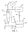
- Fig. 3 illustrates the fuel cell efficiency by the function curve of fuel cell power versus current density (in mA / cm 2 ).
- Fig. 3 shows the efficiency in a fuel cell that is fed with a single methanol solution at 90 ° and an air mixture pressure of 1.37 bar (20 PSIG). The curve shows that approximately 0.48 volts can be maintained at approximately 400 mA / cm 2 by means of the fuel cell.
- the optimization of the fuel cell requires a comparison between current density and cell efficiency.
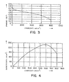
- 4 shows the power density as a function of the current density.
- the optimal operating point achieves a power density of approximately 230 mW / cm 2 .
- the optimal operating point occurs at current densities between 400 and 700 mA / cm 2 .
- the cell voltage within this range is between 0.48 and 0.31 volts. 5 shows the transient response or the transition function of the fuel cell.
- the settling time of the fuel cell is around 500-800 ms. This short settling time is suitable for use in arc welding torches, so that larger energy storage elements are not required.
- V 15 + 0.05I.
- Due to the losses in Energy conversion circuit and in the cables and due to the Compensating the welding load is a margin of safety provided by a few volts.
- the safety margin is based on experience under typical welding conditions and depends more or less on the current circumstances from.
- the cross-sectional area of the fuel cell is about the desired Load current and the operating current density of the cell are determined.
- Fig. 6 shows a welding circuit which has a power compensation converter (buck power converter).
- the table below shows the associated data for cell stack configurations when a compensation converter is used with common weld charges and operating conditions.
- the following operating conditions for the fuel cell were assumed: 220 mW / cm 2 and 500 mA / cm 2 (0.44 volts).
- the positive poles of the cell stack 110 are arranged on the side on which the oxidant is supplied and are connected to the input of the power converter circuit 200.
- the minus connection is on the side where fuel is supplied and is connected to a clamp on the workpiece 30.
- Welding circuit 200 is regulated to regulate the welding current in response to a feedback signal proportional to the welding voltage, welding current, or both. Reversing the welding electrode and workpiece connections would reverse the welding load current. For CO 2 welding processes, a structure with direct current and negative electrode is often desired.
- the cell stack 110 generates an excessive amount of CO 2 for welding.
- the CO 2 can contain trace elements of water or methanol vapor, which must be removed before the gas is fed into the arc welding torch.
- a gas dryer can be used to ensure that the gas is free of vapor contaminants.
- the fuel cell is operated at pressures which exceed ambient pressure, so that compression of the CO 2 is generally not necessary. However, if the operating pressure of the fuel cell is too low, the CO 2 gas can be compressed before it is fed to the welding arc.
- the flow rate of the shielding gas must be regulated to an appropriate level to avoid excessive arc disturbances. Since the fuel cell produces more CO 2 than is required to protect the arc, a flow regulator can be provided so that only a suitable amount of shielding gas flows. The rest of the CO 2 is suctioned off or used for other purposes.
- Fig. 6 shows the electrical connection in one configuration with direct current and positive electrode.
- a power converter circuit is used to output the fuel cell to match the welding load. 6 shows for this Purpose a compensation converter (chopper).
- the welding circuit 200 has a transistor 210, which by means of a Welding control system 220 is controlled.
- the welding control system controls the waveform of the welder supplied current.
- the welding control system can turn on feedback monitoring during the operation of the arc welding torch support.
- the welding circuit also has a diode 230 on to an appropriate current flow through the Maintain electrode through.
- the welding circuit an inductor around the one flowing through the electrode Smooth welding current waveform.
- the cell stack performance should always exceed the balancing load requirements, so that the compensation converter works effectively.
- FIG. 7 shows the topology of an additional voltage compensation converter.
- the additional voltage compensation circuit in the welding circuit 200 is constructed in such a way that the voltage at the electrode is increased without the number of fuel cells in the cell stack 110 having to be increased.
- Welding circuit 200 includes a welding control system 220 that is similar to the control system of FIG. 6.
- the welding circuit further includes an inductor 250, a capacitor 260 and a transistor 270 which is controlled by the welding control system 220 to boost the voltage through the welding circuit.
- the function of diodes 280, 290, transistor 300 and inductor 310 which operate similarly to the chopper or compensation circuit in Fig.
- FIGS. 8 and 9 schematically show control circuits for TIG welding torches.
- TIG welding When welding aluminum and similar metals TIG welding is used, whereby a non-melting Electrode such as a tungsten electrode in sufficient Distance from the workpiece is kept to an arc to get when due to an applied across the gap Voltage a current flows. Since aluminum oxidizes very quickly, it is necessary to remove the aluminum oxides from the welding surface to remove while the arc heat melts flux cored wire and deposited on the aluminum workpiece. The metal is going through Apply an AC power supply to straighten one AC current through the gap or gap between the electrode and workpiece cleaned. During a positive cycle the electrode is positive with respect to the workpiece; consequently will Electrons are emitted from the workpiece.
- This process solves and removes aluminum oxides from the surface in preparation for the immediately following negative cycle, the tungsten or other non-melting electrons negative relative to Workpiece. Electrons are taken in by the tungsten electrode Emitted towards the workpiece in order to be comparatively effective in the Arc area to be heated. By using AC over the arc become main cleaning cycles and generated heating cycles, making it a fairly efficient one TIG welding process for aluminum is created.
- the welder When using DC power sources in TIG welding the welder must select the polarity to be used. If unalloyed or stainless steel is to be welded, it does not have to be cleaned, so that DC TIG welding can be used with a negative electrode. That polarity does not provide an arc cleaning effect removing an oxide layer; if this system for aluminum welding cleaning and removal must be used as welding preparation the oxide layer on the welding surface become. However, this is only useful if heavy aluminum plates TIG-welded and the additional pre-cleaning work due to the increased welding speed when used the electrode with negative polarity. Because of this, the welder often chooses TIG welding with direct current and positive electrode, whereby then Current flows from the electrode to the workpiece. This causes in Combination with the arc welding process a cleaning effect.
- the modified direct current is then one Switching network 310 supplied.
- the switching network 310 converts the direct current into alternating current for use in one TIG welding device around.
- a wave profile 320 controls this Switch in the switching network to the duration of the positive and to control negative pulses during the welding cycle.
- a pulse width adjuster 330 represents the pulse duration of positive and / or negative Pulse on.
- Fig. 11 shows a polarity reversal circuit 340, the one from fuel cell 100 to arc welding torch 20 flowing direct current reverses. Switching the polarity can be controlled by software.
- the welding circuit is capable of a normal DC fuel cell for use with a TIG welding device convert to an AC power source.
- the Welding can also be done with melting welding electrodes be performed.
- the melting electrode is melted and on the workpiece by means of spherical transmission, Short circuit transmission, pulse current transmission etc. filed.
- the welding circuit can be used to generate a short-term reversal of current polarity can be used, which Welding as used in TIG welding.
- the welding circuit has the advantages of a normal AC TIG welding device with the additional performance, the extent of heating and cleaning the workpiece to be able to set for a short period.
- the welding circuit can regulate the ratio of plus to negative power, the amount of cleaning performed during positive current flow to control.
- the welding circuit can also be used to reduce arcing be used. Welding with melting Usually brings electrodes at high DC levels Arc warping with it due to magnetic field interactions caused by the arc plasma.
- the welding circuit can affect the effect of arcing Reduce short-term reversal of the arc current.
- the 10 is a fuel cell 100 as an energy supply shown for an STT welding torch type.
- the direct current of the Fuel cell provides power to the DC / DC circuit 300.
- the DC / DC circuit can be constructed as described in FIGS. 8 and 9 his.
- the current from the DC / DC circuit goes to the switching network 310.
- the switching network forms the desired waveform for the current on the workpiece 30.
- the switching network is controlled by a pulse width modulator (PWM) 340 that is controlled by means of an oscillator (OSC) 350.
- PWM pulse width modulator
- OSC oscillator
- the desired one Waveform for the current on the workpiece 30 is by means of the STT waveform profile 360 set.
- a background current setting device 370 and a maximum current setting device 380 are used to modify the waveform profile.
- the welding circuit can change the polarity of the waveform during a single Welding cycle or during different welding cycles Control using the polarity reversal circuit of FIG. 11.
- the electrode changes between a short-circuit condition, when the electrode touches the workpiece, and a Arc condition in which the electrode is spaced from the workpiece is back and forth.
- a electrical arc between the workpiece and the electrode for melting and maintaining the molten electrode end generated while this is for a subsequent short circuit condition is fed to the workpiece.
- the welding cycle alternates between short circuit and plasma state.
- the pulse width modulator operates at high frequencies.
- the operating frequency of the pulse width modulator is approximately 10-30 kHz, the width of the subsequent current pulse over the voltage at the waveform controller is determined. Since the Maximum welding cycle rate generally in the range of 100-400 Cycles per second are numerous updated Pulse generated during each welding cycle.
- the welding cycle directs electricity to the work area depending from operating the pulse width modulator controller until the functions dr / dt (where r is the electron resistance), di / dt or dv / dt an impending burnout during the pinch cycle Show. As soon as this is detected, the Welding circuit between the electrode and the workpiece caused current flow immediately reduced to a lower level.
- the background current circuit continues to apply a current of 5-7 A regardless of the operating condition of the welding circuit on.
- the background current ensures that a Current of at least 5-7 A at any time during the welding cycle flows between the electrode and the workpiece, causing a Extinguishing the arc between the electrode and the workpiece is prevented during each phase of the welding cycle.
- the electrode 60 is preferably a melting one Soul electrode, which has an outer metal shell and a Has electrode core. It is understood that alternatively the Electrode coated or could be a solid wire.
- the metal one Electrode sheath is preferably made of carbon steel, stainless steel or other metal or metal alloy.
- the composition of the metal shell is preferably such chosen to be similar to the metal composition of the Workpiece.
- the electrode core preferably has flux additives and / or alloys and metals.
- the flux can contain ingredients to create a slag over the weld pool to protect the weld pool until it hardens, to hold the weld pool in position until it hardens and / or around the weld metal during the formation of the weld pool shield.
- the flux can also contain components form the shielding gas to prejudice the root bed Protect environmental impacts.
- the alloy additives are preferred enclosed in the electrode core.
- the alloy additives are preferably chosen such that the alloy additives in coordination with the composition of the metal electrode sleeve form a weld pool that has a composition that is similar to the metal composition of the workpiece.
- Fig. 10 shows a desired current profile to minimize splashing during welding.
- This welding profile is in a pinch section, a plasma amplification section, a Plasma section and a background section divided, wherein the arc is maintained.
- the plasma amplification section which is the critical area in the operation of the control system against splashes is the constant here Current section before the decay section; the decay section can however also the end of the plasma amplification section or be assigned to the beginning of the plasma section.
- the current control circuit changes to the decay section the background current level, which is the plasma or arc maintains.
- the current control circuit holds a preselected one according to the invention Background current level up, which prevents the current level at the arc at some point below the selected one Low current level could drop at which the arc extinguish would.
- the current control circuit is designed so that it does everything Melting of the electrode during the plasma amplification - and plasma portion of the welding cycle. Another meltdown the electrode does not find on background current level instead of the resistance current required to melt the electrode with the arc only by means of background current maintaining current level is not available stands. The background current is therefore only used to maintain of the arc and the drop of molten metal in the melt state.
- the amount of molten metal on Electrode end by the plasma amplification and the plasma is formed is chosen such that it has a predetermined volume melts from molten metal at the electrode end, and the plasma portion of the stream is lowered to background current, once the predetermined volume is obtained. The duration the plasma amplification and plasma section can also be selected become.
- the molten metal from the weld pool until the desired amount of molten metal from Electrode end was melted.
- the one at the end of the electrode desired amount of molten metal is through Establishing a preselected amount of energy or wattage during the plasma portion of the welding cycle into the electrode controlled into it.
- the melting ball is Shielding gas shielded from the atmosphere.
- the inert gas inflow will continue until the melted ball into the molten metal was transferred into it. As soon as the molten metal ball and plasma portion of the welding cycle the molten ball is pushed forward by the electrode drawn into the weld pool, causing a short circuit condition is formed. When the melted metal ball is the melted one Metal bath is reached, it is caused by surface tension pulled into the bathroom. This results in the very last constriction that extending between the bath and the electrode wire molten metal, and then occurs Demolition and separation of the ball from the wire. There during there is only a low background current in the separation, little splashing may occur.
- the Current control circuitry pinching the molten metal ball such that the current flow during the pinch curve is stronger increases when the constriction changes extremely quickly in diameter reduced through electrical holes until an impending Breakthrough is detected. Once the detection of an impending Breakdown occurs, the current is at the background current level lowered until the molten metal at the electrode end passes into the weld pool.
- the current can be positive at any time, at any time negative or a combination of positive and negative Be pulsing.
- the Number of current cycles of positive polarity and negative polarity controlled to the desired heating in the melted Obtain metal puddle of the welding process. If the puddle is too is cold, the number of cycles becomes 320 with negative polarity increased relative to the number of cycles of positive current.
- the desired ratio is determined by a suitable selection circuit received in the welding controller.
- An alternative control concept can also be used, where every welding cycle starts with a standard cycle is negative polarity, which subsequently becomes a predetermined one Time in the cycle switched to a cycle with positive polarity becomes.
- the polarity of the quickly generated current pulse are switched after the plasma amplification section has ended. This will Final flank section into a negative section and a positive section divided with sudden polarity reversal. in the Connection, the current cycle has a positive polarity to the end of the cycle. In this way, the sweat puddle heat is through Selection of the time delay of polarity reversal during the welding cycle certainly.
- To control at an STT welding device the heat in the welding process between a positive polarity and switch a negative polarity of the current pulses back and forth, further modifications could be made.
Abstract
Description
| Zellenstapelkonfiguration--Leistungs-Kompensationskonverterstufe | ||||||
| Schweißstrom | Schweiß spannung | Lastleistung | Spannungsreserve | Gesamtspannung | Zellenanzahl im Zellenstapel | Zellenquerschnittsfläche (cm2) |
| 0 | 15.0 | 0.0 | 13 | 28 | 63 | 0 |
| 100 | 20.0 | 2.0 | 14 | 34 | 77 | 113 |
| 150 | 22.5 | 3.4 | 14.5 | 37 | 84 | 175 |
| 300 | 30.0 | 9.0 | 16 | 46 | 104 | 376 |
| 400 | 35.0 | 14.0 | 17 | 52 | 118 | 516 |
| 500 | 40.0 | 20.0 | 18 | 58 | 131 | 664 |
| Zellenstapelkonfiguration - Kompensationsleistungskonverterstufe | ||||||||
| Zellenanzahl im Stack = | 35 | 45 | 60 | 75 | 100 | 125 | ||
| Zellenstapelspannung = | 15,4 | 19,8 | 26,4 | 33,0 | 44,0 | 55,0 | ||
| Schweiß strom (A) | Schweiß spannung (V) | Lastleistung (KW) | Zellenquerschnitts fläche (cm2) | Zellenquerschnitts fläche (cm2) | Zellenquerschnitts fläche (cm2) | Zellenquerschnitts fläche (cm2) | Zellenquerschnitts fläche (cm2) | Zellenquer schnittfläche (cm2) |
| 0 | 15.0 | 0.0 | 0 | 0 | 0 | 0 | 0 | 0 |
| 100 | 20.0 | 2.0 | 248 | 193 | 145 | 116 | 87 | 70 |
| 150 | 22.5 | 3.4 | 419 | 326 | 245 | 196 | 147 | 117 |
| 200 | 25.0 | 5.0 | 621 | 483 | 362 | 290 | 217 | 174 |
| 300 | 30.0 | 9.0 | 1118 | 870 | 652 | 522 | 391 | 313 |
| 400 | 35.0 | 14.0 | 1739 | 1353 | 1014 | 812 | 609 | 487 |
| 500 | 40.0 | 20.0 | 2484 | 1932 | 1449 | 1159 | 870 | 696 |
Claims (44)
- Lichtbogenschweißvorrichtung zum Ausbilden einer Schweißraupe auf einem Werkstück (30), aufweisend eine elektrische Energiequelle (90), einen Schweißschaltkreis (200), und eine Schweißelektrode, dadurch gekennzeichnet, daß die elektrische Energiequelle (90) zumindest eine Brennstoffzelle (100) umfaßt, die Spannung und Strom für den Sohweißschaltkreis (200) erzeugt, um zumindest teilweise ein Ausbilden eines elektrischen Lichtbogens zwischen Elektrode (60) und Werkstück (30) zu erzwingen, wobei die Brennstoffzelle (100) eine Anode, eine Kathode und zumindest eine zwischen der Anode und der Kathode angeordnete, protonenleitende Feststoff-Polymermembran, ein organisches Versorgungsmittel und einen Mechanismus beinhaltet, mit dem das organische Versorgungsmittel an der Anode vorbeiführbar ist.
- Vorrichtung nach Anspruch 1, wobei die elektrische Energiequelle (90) eine Mehrzahl von Brennstoffzellen, insbesondere einen Zellenstapel (110) aus Brennstoffzellen umfaßt.
- Vorrichtung nach Anspruch 1 oder 2, dadurch gekennzeichnet, daß die Brennstoffzelle flüssiggespeist ist.
- Vorrichtung nach einem der Ansprüche 1 bis 4, dadurch gekennzeichnet, daß die Brennstoffzelle ein Gasreaktionsprodukt bildet, das zumindest teilweise eine Schutzgasquelle während der Ausbildung der Schweißraupe versorgt.
- Vorrichtung nach einem der Ansprüche 1 bis 4, dadurch gekennzeichnet, daß die Brennstoffzelle eine indirekte Brennstoffzelle, eine direkte Brennstoffzelle oder eine Kombination aus indirekter und direkter Brennstoffzelle ist.
- Vorrichtung nach einem der Ansprüche 1 bis 5, dadurch gekennzeichnet, daß das organische Versorgungsmittel (Brennstoffmittel) aus Methanol, Formaldehyd, Formylsäure, Dimetoxydmethan, Trimetoxydmethan, Trioxan oder aus Kombinationen hieraus besteht.
- Vorrichtung nach einem der Ansprüche 4 bis 6, dadurch gekennzeichnet, daß das Gasreaktionsprodukt eine Kohlenstoffbindung aufweist, die insbesondere ein Gas aus der Gruppe von Kohlenmonoxyd, Kohlendioxyd oder Mischungen hieraus aufweist.
- Vorrichtung nach einem der Ansprüche 1 bis 7, dadurch gekennzeichnet, daß die Anode aus einem Metall besteht, das aus der Gruppe von Platin-Rutheniumlegierung, Platin-Zinn, Platin-Iridium, Platin-Osmium, Platin-Renium oder Mischungen daraus ausgewählt ist.
- Vorrichtung nach einem der Ansprüche 1 bis 8, dadurch gekennzeichnet, daß die protonleitende Polymermembran ein Material aufweist, das aus einer Gruppe ausgewählt ist, die aus einem Copolymer von Tetrafluorethylen und perfluorinierter Sulfonsäure, perfluoriniertem Sulfonsäurepolymer, Polykohlenwasserstoff-Sulfonsäure oder eine Mischung daraus besteht.
- Vorrichtung nach einem der Ansprüche 1 bis 9, dadurch gekennzeichnet, daß die protonleitende Polymermembran einen Katalysator umfaßt, der ein Material aufweist, das aus der Gruppe ausgewählt ist, die aus Ir,Mo,Nb,Nu,Os,Pd,Pt,Re,Ru, RuO2, Sn, SnO2, Ti, W, WO3, Zr oder Kombinationen hieraus besteht.
- Vorrichtung nach einem der Ansprüche 1 bis 10, gekennzeichnet durch wenigstens zwei protonleitende, feste Polymermembranen, wobei die eine der Polymermembranen eine andere Zusammensetzung als die andere Polymermembran hat.
- Vorrichtung nach einem der Ansprüche 1 bis 11, dadurch gekennzeichnet, daß die Kathode Platin aufweist.
- Vorrichtung nach einem der Ansprüche 1 bis 12, dadurch gekennzeichnet, daß der Schweißschaltkreis (200) die Spannung der elektrischen Energiequelle (90) verstärkt.
- Vorrichtung nach Anspruch 13, dadurch gekennzeichnet, daß der Schweißschaltkreis (200) einen Schweißstromschaltkreis umfaßt, der die Elektrode (60) mit Strom versorgt, wobei der Schweißstromschaltkreis eine erste Schaltung zum Erzeugen eines Übergangsstroms und eine zweite Schaltung zum Erzeugen eines Schmelzstroms aufweist, wobei die zweite Schaltung eine ausreichende Menge von Strom an die Elektrode liefert, um die Schweißraupe auf dem Werkstück (30) auszubilden.
- Vorrichtung nach Anspruch 14, dadurch gekennzeichnet, daß die zweite Schaltung eine vorgewählte Energiemenge zum Schweißdraht (60) lenkt, um ein vergleichsweise konstantes Volumen der Elektrode während jedem Schweißzyklus abzuschmelzen.
- Vorrichtung nach Anspruch 14 oder 15, dadurch gekennzeichnet, daß die zweite Schaltung die an die Elektrode (60) gelieferte Strommenge reduziert, bevor geschmolzenes Material an der Elektrode einen Kurzschluß mit dem Werkstück (30) bildet.
- Vorrichtung nach einem der Ansprüche 14 bis 16, dadurch gekennzeichnet, daß die erste Schaltung einen Hochstrompuls am Ende eines Kurzschlußzustands zwischen der Elektrode (60) und dem Werkstück (30) liefert und daß der Puls bis kurz vor einer vorberechneten Beendigung des Kurzschlußzustandes angelegt bleibt.
- Vorrichtung nach einem der Ansprüche 13 bis 17, dadurch gekennzeichnet, daß die erste Schaltung die Strommenge am Schweißdraht reduziert, bevor das aufgeschmolzene Material an der Elektrode (60) einen Kurzschlußzustand mit dem Werkstück (30) bildet.
- Vorrichtung nach einem der Ansprüche 1 bis 18, wobei der Schweißschaltkreis (200) einen Strompolaritätsregler zum Regeln der Polarität zumindest eines Abschnitts des die Elektrode durchfließenden Stroms aufweist.
- Vorrichtung nach Anspruch 19, dadurch gekennzeichnet, daß der Schweißschaltkreis (200) eine Serie von Strompulsen geringer Pulsbreite erzeugt, die einen Schweißzyklus mit einem Kurzschlußübertragungsabschnitt und einem Plasmalichtbogenschmelzabschnitt ausbilden, wobei die Strompulse in dem Zyklus jeweils eine vorgegebene elektrische Polarität haben, die mittels der Polaritätssteureinrichtung zwischen einer ersten Polarität, die positiv ist, und einer zweiten Polarität, die negativ ist, wählbar ist.
- Vorrichtung nach Anspruch 19 oder 20, dadurch gekennzeichnet, daß die Polaritätssteureinrichtung einen Decoder umfaßt, der in einem ersten Zustand zwischen einer ersten oder zweiten Polarität für eine Anzahl von aufeinanderfolgenden Schweißzyklen und in einem zweiten Zustand die jeweils andere Polarität für eine zweite Anzahl von aufeinanderfolgenden Schweißzyklen wählen kann, und einen Mechanismus zum Umschalten zwischen dem ersten und zweiten Zustand im Schweißbetrieb.
- Vorrichtung nach Anspruch 21, dadurch gekennzeichnet, daß jeder Zyklus einen gewünschten Lichtbogenstrom und einen Nebenschlußwiderstand (shunt) zum Abtasten des aktuellen Lichtbogenstroms und einen Fehlerverstärker zum Vergleichen des aktuellen Lichtbogenstroms mit dem erwünschten Lichtbogenstrom aufweist, um die Strompulsbreiten zu steuern.
- Vorrichtung nach einem der Ansprüche 19 bis 22, dadurch gekennzeichnet, daß die Polaritätssteuereinrichtung eine positive oder negative Polarität während eines ersten Abschnitts des durch die Elektrode hindurchgeleiteten Stroms aufrechthält.
- Vorrichtung nach einem der Ansprüche 19 bis 23, dadurch gekennzeichnet, daß der Polaritätssteuerer den Strom während einer ersten Zeitdauer mit positiver Polarität und während einer zweiten Zeitdauer mit negativer Polarität aufrechthält, wobei vorzugsweise die erste Zeitdauer größer als die zweite Zeitdauer ist.
- Vorrichtung nach einem der Ansprüche 19 bis 24, dadurch gekennzeichnet, daß der Schweißschaltkreis einen zentral angezapften Induktor mit einem ersten Abschnitt zum Erzeugen einer ersten Polarität und einem zweiten Abschnitt zum Erzeugen einer zweiten Polarität, einen ersten Schalter zum Verbinden des ersten Induktorabschnitts zwischen der Elektrode und dem Werkstück, einen zweiten Schalter zum Verbinden des zweiten Abschnitts des Induktors zwischen Elektrode und Werkstück, und ein Einstellmittel zum Schließen entweder des ersten Schalters oder des zweiten Schalters während eines vorgegebenen Schweißzyklus, aufweist.
- Vorrichtung nach einem der Ansprüche 1 bis 25, dadurch gekennzeichnet, daß die Elektrode eine abschmelzende Elektrode mit Metallkern und Flußmittel ist.
- Verfahren zum Ausbilden einer Schweißraupe auf einem Werkstück beim elektrischen Lichtbogenschweißen, mit den Schritten:dadurch gekennzeichnet, daß die elektrische Energiequelle von einer Brennstoffzelle (100) gebildet wird.a) Bereitstellen einer Elektrode;b) Bereitstellen einer elektrischen Energiequelle, die einen Strom erzeugt;c) Bereitstellen eines Schweißschaltkreises, undd) Liefern des Stromes an den Schweißschaltkreis, um einen Lichtbogen zwischen Elektrode und Werkstück auszubilden,
- Verfahren nach Anspruch 27, dadurch gekennzeichnet, daß der Schweißschaltkreis (200) zumindest teilweise die Wellenform des die Elektrode durchfließenden Stroms steuert.
- Verfahren nach Anspruch 27 oder 28, dadurch gekennzeichnet, daß die Elektrode eine abschmelzende Metallseelendrahtelektrode ist.
- Verfahren nach einem der Ansprüche 27 bis 29, dadurch gekennzeichnet, daß mit dem Schweißschaltkreis eine elektrische Wellenform an der Elektrode ausgebildet wird, die einen Kurzschlußübertragungsabschnitt und einen kontrollierten Schmelzabschnitt aufweist.
- Verfahren nach Anspruch 30, dadurch gekennzeichnet, daß der gesteuerte Schmelzabschnitt gebildet wird durch Anlegen einer vorbestimmten Energiemenge an der Elektrode oder Anlegen einer vorbestimmten Leistungsmenge an der Elektrode.
- Verfahren nach einem der Ansprüche 27 bis 31, dadurch gekennzeichnet, daß der Schweißschaltkreis einen Hintergrundstrom erzeugt, wobei der Hintergrundstrom eine Komponente mit hoher Induktanz und ein Niedrigniveau hat, das gerade oberhalb desjenigen Niveaus liegt, um einen Lichtbogen zwischen Elektrode und Werkstück während des gesamten Schweißzyklus zu erhalten.
- Verfahren nach einem der Ansprüche 27 bis 31, dadurch gekennzeichnet, daß der Schweißschaltkreis die Polarität der an die Elektrode gelieferten Wellenform steuert.
- Verfahren nach Anspruch 33, dadurch gekennzeichnet, daß die elektrische Wellenform eine Serie kurzer Strompulsbreiten aufweist, die jeweils eine vorgegebene elektrische Polarität haben.
- Verfahren nach Anspruch 33 oder 34, dadurch gekennzeichnet, daß die Polarität der elektrische Welle während des Schweißzyklus zwischen einer Pluspolarität und einer Minuspolarität hin- und hergeschaltet wird.
- Verfahren nach einem der Ansprüche 33 bis 35, dadurch gekennzeichnet, daß die Polarität der elektrischen Welle als Funktion der an Elektrode und Werkstück angelegten, aufsummierten Energiemenge in der einer Polarität bzw. der an Werkstück und Elektrode in der anderen Polarität angelegten, aufsummierten Energiemenge gewechselt wird.
- Verfahren nach einem der Ansprüche 27 bis 26, wobei der Schweißschaltkreis die Spannung der elektrischen Energiequelle verstärkt.
- Verfahren nach einem der Ansprüche 27 bis 37, dadurch gekennzeichnet, daß die Brennstoffzelle aus einer indirekten Brennstoffzelle, einer direkten Brennstoffzelle oder einer Kombination hieraus besteht.
- Verfahren nach einem der Ansprüche 27 bis 38, dadurch gekennzeichnet, daß die Brennstoffzelle mit organischem Brennstoff gespeist wird, wobei der organische Brennstoff aus einer Gruppe ausgewählt ist, die Methanol, Formaldehyd, Formylsäure, Dimetoxymethan, Trimytoxymethan, Trioxan oder Kombinationen enthält.
- Verfahren nach einem der Ansprüche 27 bis 39, wobei die Brennstoffzelle mit flüssigem Brennstoff gespeist wird.
- Verfahren nach einem der Ansprüche 27 bis 40, dadurch gekennzeichnet, daß die Brennstoffzelle bei der Energieerzeugung ein Gas bildet, das zumindest teilweise als Schutzgas verwendet werden kann und insbesondere während der Ausbildung der Schweißraupe dem Werkstück zugeführt wird.
- Verfahren nach einem der Ansprüche 27 bis 41, wobei die Brennstoffzelle eine Anode, eine Kathode und zumindest eine zwischen Anode und Kathode angeordnete feste, protonleitende Polymermembran umfaßt.
- Verfahren nach einem der Ansprüche 27 bis 42, wobei die Brennstoffzelle als Zellenstapel (110) aus einer Mehrzahl von Brennstoffzellen (100) gebildet wird.
- Verwendung einer Brennstoffzelle (100) zur Strom- und Spannugsversorgung in einer Lichtbogenschweißvorrichtung nach einem der Ansprüche 1 bis 26 oder in einem Lichtbogenschweißverfahren nach einem der Ansprüche 27 bis 43.
Priority Applications (1)
| Application Number | Priority Date | Filing Date | Title |
|---|---|---|---|
| EP03021339A EP1378311B1 (de) | 1999-12-08 | 2000-12-05 | Lichtbogenschweissvorrichtung und -verfahren mit einer Stapeleinheit von Brennstoffzellen |
Applications Claiming Priority (2)
| Application Number | Priority Date | Filing Date | Title |
|---|---|---|---|
| US457156 | 1999-12-08 | ||
| US09/457,156 US6331694B1 (en) | 1999-12-08 | 1999-12-08 | Fuel cell operated welder |
Related Child Applications (1)
| Application Number | Title | Priority Date | Filing Date |
|---|---|---|---|
| EP03021339A Division EP1378311B1 (de) | 1999-12-08 | 2000-12-05 | Lichtbogenschweissvorrichtung und -verfahren mit einer Stapeleinheit von Brennstoffzellen |
Publications (3)
| Publication Number | Publication Date |
|---|---|
| EP1106295A2 true EP1106295A2 (de) | 2001-06-13 |
| EP1106295A3 EP1106295A3 (de) | 2003-04-23 |
| EP1106295B1 EP1106295B1 (de) | 2006-05-17 |
Family
ID=23815667
Family Applications (2)
| Application Number | Title | Priority Date | Filing Date |
|---|---|---|---|
| EP03021339A Expired - Lifetime EP1378311B1 (de) | 1999-12-08 | 2000-12-05 | Lichtbogenschweissvorrichtung und -verfahren mit einer Stapeleinheit von Brennstoffzellen |
| EP00126415A Expired - Lifetime EP1106295B1 (de) | 1999-12-08 | 2000-12-05 | Lichtbogenschweissvorrichtung und -verfahren mit Brennstoffzelle |
Family Applications Before (1)
| Application Number | Title | Priority Date | Filing Date |
|---|---|---|---|
| EP03021339A Expired - Lifetime EP1378311B1 (de) | 1999-12-08 | 2000-12-05 | Lichtbogenschweissvorrichtung und -verfahren mit einer Stapeleinheit von Brennstoffzellen |
Country Status (14)
| Country | Link |
|---|---|
| US (3) | US6331694B1 (de) |
| EP (2) | EP1378311B1 (de) |
| JP (1) | JP3537760B2 (de) |
| KR (1) | KR100417274B1 (de) |
| CN (1) | CN1212215C (de) |
| AT (2) | ATE363358T1 (de) |
| AU (1) | AU747929B2 (de) |
| CA (1) | CA2326024C (de) |
| DE (2) | DE50012760D1 (de) |
| EG (1) | EG22208A (de) |
| ID (1) | ID28594A (de) |
| NZ (1) | NZ508710A (de) |
| RU (1) | RU2220827C2 (de) |
| SG (1) | SG86449A1 (de) |
Cited By (4)
| Publication number | Priority date | Publication date | Assignee | Title |
|---|---|---|---|---|
| EP1284154A2 (de) * | 2001-08-16 | 2003-02-19 | Mitsubishi Denki Kabushiki Kaisha | Elektrochemisches Element und Vorrichtung mit elektrochemischer Vorrichtung |
| DE10163841A1 (de) * | 2001-12-22 | 2003-07-03 | Xcellsis Ag | Fahrzeug mit einem Brennstoffzellensystem |
| EP1342282A1 (de) * | 2000-11-14 | 2003-09-10 | The Regents of The University of California | Direkt-methanol-brennstoffzelle mit luftatmung |
| EP2615677A1 (de) * | 2012-01-11 | 2013-07-17 | Samsung Electronics Co., Ltd | Hybrider Schalldämpfer mit Gas-Flüssigkeitstrennungsfunktion in Brennstoffzellensystemen |
Families Citing this family (114)
| Publication number | Priority date | Publication date | Assignee | Title |
|---|---|---|---|---|
| US6331694B1 (en) * | 1999-12-08 | 2001-12-18 | Lincoln Global, Inc. | Fuel cell operated welder |
| DE10019770B4 (de) * | 2000-04-20 | 2006-12-07 | Nucellsys Gmbh | Verfahren zur Verbesserung des Anspringverhaltens von mobilen Brennstoffzellensystemen |
| CA2352626A1 (fr) | 2001-07-12 | 2003-01-12 | Co2 Solution Inc. | Couplage d'une pile a hydrogene a un bioreacteur enzymatique de transformation et sequestration du co2 |
| CA2353307A1 (fr) | 2001-07-13 | 2003-01-13 | Carmen Parent | Appareil et procede pour le traitement des effluents gazeux |
| WO2003064103A1 (fr) * | 2002-01-31 | 2003-08-07 | Jfe Steel Corporation | Fil d'acier pour soudage a l'arc avec protection au dioxyde de carbone et processus de soudage utilisant ce fil d'acier |
| US7267899B2 (en) * | 2002-03-08 | 2007-09-11 | Van Zee John W | Method and system for improving the performance of a fuel cell |
| US7396605B2 (en) * | 2002-03-08 | 2008-07-08 | Van Zee John W | Method and system for improving the performance of a fuel cell |
| CA2405635A1 (en) | 2002-09-27 | 2004-03-27 | C02 Solution Inc. | A process and a plant for the production of useful carbonated species and for the recycling of carbon dioxide emissions from power plants |
| US6989509B2 (en) * | 2003-03-17 | 2006-01-24 | Lincoln Global, Inc. | Self-contained integrated welder/generator and compressor |
| JP4066901B2 (ja) * | 2003-07-03 | 2008-03-26 | ソニー株式会社 | 電源アダプタ及び電力供給システム |
| US6982398B2 (en) | 2004-06-01 | 2006-01-03 | Illinois Tool Works Inc. | Fuel saving engine driven welding-type device and method of use |
| US20070187376A1 (en) * | 2003-11-26 | 2007-08-16 | Illinois Tool Works Inc. | Welder or Cutter Using an Energy Storage Device With Or Without a Charger |
| US7183517B2 (en) * | 2003-11-26 | 2007-02-27 | Illinois Tool Works, Inc. | Portable welding-type apparatus with interchangeable energy storage device |
| US7188645B2 (en) * | 2003-12-24 | 2007-03-13 | Lincoln Global, Inc. | Visual fuel system for an engine welder |
| US6992265B2 (en) * | 2004-01-15 | 2006-01-31 | Lincoln Global, Inc. | Integrated engine welder and electric compressor |
| US6924460B1 (en) * | 2004-01-27 | 2005-08-02 | Lincoln Global, Inc. | Engine welder with shielding gas generation |
| US7053334B2 (en) | 2004-03-01 | 2006-05-30 | Lincoln Global, Inc. | Electric arc welder system with waveform profile control |
| US20070215585A1 (en) | 2006-03-15 | 2007-09-20 | Lincoln Global, Inc. | High current AC welder |
| US8080761B2 (en) * | 2004-08-17 | 2011-12-20 | Lincoln Global, Inc. | Hybrid powered welder |
| US9333580B2 (en) * | 2004-04-29 | 2016-05-10 | Lincoln Global, Inc. | Gas-less process and system for girth welding in high strength applications |
| US20070221643A1 (en) * | 2004-04-29 | 2007-09-27 | Lincoln Global, Inc. | Gas-less process and system for girth welding in high strength applications including liquefied natural gas storage tanks |
| US7166817B2 (en) * | 2004-04-29 | 2007-01-23 | Lincoln Global, Inc. | Electric ARC welder system with waveform profile control for cored electrodes |
| US8759715B2 (en) | 2004-10-06 | 2014-06-24 | Lincoln Global, Inc. | Method of AC welding with cored electrode |
| US7842903B2 (en) * | 2005-10-31 | 2010-11-30 | Lincoln Global, Inc. | Short arc welding system |
| US8704135B2 (en) * | 2006-01-20 | 2014-04-22 | Lincoln Global, Inc. | Synergistic welding system |
| US9393635B2 (en) * | 2004-06-04 | 2016-07-19 | Lincoln Global, Inc. | Adaptive GMAW short circuit frequency control and high deposition arc welding |
| US7304269B2 (en) * | 2004-06-04 | 2007-12-04 | Lincoln Global, Inc. | Pulse welder and method of using same |
| US8269141B2 (en) | 2004-07-13 | 2012-09-18 | Lincoln Global, Inc. | Power source for electric arc welding |
| US8785816B2 (en) | 2004-07-13 | 2014-07-22 | Lincoln Global, Inc. | Three stage power source for electric arc welding |
| US8581147B2 (en) | 2005-03-24 | 2013-11-12 | Lincoln Global, Inc. | Three stage power source for electric ARC welding |
| US9956639B2 (en) | 2005-02-07 | 2018-05-01 | Lincoln Global, Inc | Modular power source for electric ARC welding and output chopper |
| US20080044719A1 (en) * | 2005-02-02 | 2008-02-21 | Symyx Technologies, Inc. | Platinum-copper-titanium fuel cell catalyst |
| US9855620B2 (en) | 2005-02-07 | 2018-01-02 | Lincoln Global, Inc. | Welding system and method of welding |
| US7992760B2 (en) * | 2005-02-09 | 2011-08-09 | The United States Of America As Represented By The Administrator Of The National Aeronautics And Space Administration | Conduit purging device and method |
| US9647555B2 (en) | 2005-04-08 | 2017-05-09 | Lincoln Global, Inc. | Chopper output stage for arc welder power source |
| US7989732B2 (en) * | 2005-06-15 | 2011-08-02 | Lincoln Global, Inc. | Method of AC welding using a flux cored electrode |
| WO2007011004A1 (ja) * | 2005-07-15 | 2007-01-25 | Kyoto University | 固体高分子形燃料電池用耐co被毒多成分系電極触媒 |
| AT502422B1 (de) * | 2005-09-09 | 2007-06-15 | Fronius Int Gmbh | Verfahren zum betreiben eines wasserdampfplasmabrenners und wasserdampf-schneidgerät |
| US10099308B2 (en) * | 2006-02-09 | 2018-10-16 | Illinois Tool Works Inc. | Method and apparatus for welding with battery power |
| US7615719B2 (en) | 2006-09-11 | 2009-11-10 | Hypertherm, Inc. | Autonomous plasma cutting system |
| US8350182B2 (en) | 2006-09-11 | 2013-01-08 | Hypertherm, Inc. | Portable autonomous material processing system |
| US8946596B2 (en) * | 2006-10-05 | 2015-02-03 | Lincoln Global, Inc. | Multiple welding using a single power source |
| WO2008051829A2 (en) * | 2006-10-20 | 2008-05-02 | Swagelok Company | Welding purge control using electronic flow control |
| US20100047631A1 (en) * | 2006-10-24 | 2010-02-25 | Utc Power Corporation | Membrane electrode assembly having protective layer and method for mitigating membrane decay |
| US20080257719A1 (en) * | 2007-04-21 | 2008-10-23 | Ted Suratt | Apparatus And Method For Making Flammable Gas |
| NO328089B1 (no) * | 2007-09-03 | 2009-11-30 | Weltec As | Dekkgasstromningsstyrer for et sveiseapparat |
| DE102008011450A1 (de) * | 2008-02-27 | 2009-09-10 | Messer Group Gmbh | Vorrichtung zum Schutzgasschweißen |
| US9662736B2 (en) * | 2008-06-27 | 2017-05-30 | Linclon Global, Inc. | CO2 globular transfer |
| CN102422472B (zh) * | 2009-04-27 | 2015-02-11 | 日本戈尔有限公司 | 燃料电池用阳极侧催化剂组合物及固体高分子型燃料电池用膜电极接合体(mea) |
| US8405001B2 (en) * | 2009-07-13 | 2013-03-26 | Illinois Tool Works Inc | Hybrid welding systems and devices |
| US8569652B2 (en) * | 2009-11-17 | 2013-10-29 | Illinois Tool Works Inc. | Incremental hybrid welding systems and methods |
| US10421143B2 (en) | 2009-11-17 | 2019-09-24 | Illinois Tool Works Inc. | Energy storage caddy for a welding system |
| JP2011161514A (ja) * | 2010-01-14 | 2011-08-25 | Denso Corp | 銅溶接方法及び銅溶接装置 |
| JP5450221B2 (ja) * | 2010-04-14 | 2014-03-26 | 株式会社神戸製鋼所 | 高電流密度ガスシールドアーク溶接方法 |
| GB201012982D0 (en) * | 2010-08-03 | 2010-09-15 | Johnson Matthey Plc | Catalyst |
| JP5287962B2 (ja) * | 2011-01-26 | 2013-09-11 | 株式会社デンソー | 溶接装置 |
| CN104066541B (zh) * | 2011-11-13 | 2017-05-17 | 维克托设备公司 | 用于gmaw手动/自动mig电弧焊枪的具有至少一个从外部延伸至内腔的狭槽的中空接触尖头扩散器;具有所述接触尖头扩散器的电弧焊接装置 |
| US9403233B2 (en) * | 2011-12-16 | 2016-08-02 | Illinois Tool Works Inc. | DC electrode negative rotating arc welding method and system |
| US9862050B2 (en) | 2012-04-03 | 2018-01-09 | Lincoln Global, Inc. | Auto steering in a weld joint |
| US10239145B2 (en) | 2012-04-03 | 2019-03-26 | Lincoln Global, Inc. | Synchronized magnetic arc steering and welding |
| US9511442B2 (en) | 2012-07-27 | 2016-12-06 | Illinois Tool Works Inc. | Adaptable rotating arc welding method and system |
| US9522438B2 (en) | 2012-11-09 | 2016-12-20 | Hypertherm, Inc. | Battery-controlled plasma arc torch system |
| US10040143B2 (en) | 2012-12-12 | 2018-08-07 | Illinois Tool Works Inc. | Dabbing pulsed welding system and method |
| US10906114B2 (en) | 2012-12-21 | 2021-02-02 | Illinois Tool Works Inc. | System for arc welding with enhanced metal deposition |
| US9950383B2 (en) | 2013-02-05 | 2018-04-24 | Illinois Tool Works Inc. | Welding wire preheating system and method |
| US10835983B2 (en) * | 2013-03-14 | 2020-11-17 | Illinois Tool Works Inc. | Electrode negative pulse welding system and method |
| US10035211B2 (en) * | 2013-03-15 | 2018-07-31 | Lincoln Global, Inc. | Tandem hot-wire systems |
| US10086465B2 (en) | 2013-03-15 | 2018-10-02 | Lincoln Global, Inc. | Tandem hot-wire systems |
| US11045891B2 (en) | 2013-06-13 | 2021-06-29 | Illinois Tool Works Inc. | Systems and methods for anomalous cathode event control |
| US10543549B2 (en) | 2013-07-16 | 2020-01-28 | Illinois Tool Works Inc. | Additive manufacturing system for joining and surface overlay |
| US9770776B2 (en) | 2013-09-12 | 2017-09-26 | Lincoln Global, Inc. | Alternative power for engine driven welder |
| US10543551B2 (en) | 2013-09-16 | 2020-01-28 | Illinois Tool Works Inc. | Synchronized rotating arc welding method and system |
| US10953484B2 (en) | 2013-09-16 | 2021-03-23 | Illinois Tool Works Inc. | Narrow groove welding method and system |
| US10828728B2 (en) | 2013-09-26 | 2020-11-10 | Illinois Tool Works Inc. | Hotwire deposition material processing system and method |
| GB201320888D0 (en) * | 2013-11-27 | 2014-01-08 | Linde Aktiengesellshcaft | Additive manufacturing of titanium article |
| RU2570609C2 (ru) * | 2014-01-09 | 2015-12-10 | Общество с ограниченной ответственностью "Контрольно-Диагностический центр" | Способ сварки в среде защитных газов |
| US10464168B2 (en) | 2014-01-24 | 2019-11-05 | Lincoln Global, Inc. | Method and system for additive manufacturing using high energy source and hot-wire |
| US9550251B2 (en) | 2014-03-28 | 2017-01-24 | Hypertherm, Inc. | Power supply assembly for a plasma arc torch system |
| US11154946B2 (en) | 2014-06-30 | 2021-10-26 | Illinois Tool Works Inc. | Systems and methods for the control of welding parameters |
| US11198189B2 (en) | 2014-09-17 | 2021-12-14 | Illinois Tool Works Inc. | Electrode negative pulse welding system and method |
| CN104526115B (zh) * | 2014-11-04 | 2017-01-18 | 南方增材科技有限公司 | 核电站压力容器筒体电熔成形方法 |
| CN104526171B (zh) * | 2014-11-04 | 2016-10-12 | 南方增材科技有限公司 | 金属构件电熔成形方法 |
| US10596652B2 (en) | 2014-11-13 | 2020-03-24 | Illinois Tool Works Inc. | Systems and methods for fuel level monitoring in an engine-driven generator |
| US11478870B2 (en) | 2014-11-26 | 2022-10-25 | Illinois Tool Works Inc. | Dabbing pulsed welding system and method |
| US10189106B2 (en) | 2014-12-11 | 2019-01-29 | Illinois Tool Works Inc. | Reduced energy welding system and method |
| US11370050B2 (en) | 2015-03-31 | 2022-06-28 | Illinois Tool Works Inc. | Controlled short circuit welding system and method |
| US10974337B2 (en) | 2015-08-17 | 2021-04-13 | Illinois Tool Works Inc. | Additive manufacturing systems and methods |
| EP3345710A4 (de) * | 2015-09-03 | 2018-10-31 | Panasonic Intellectual Property Management Co., Ltd. | Lichtbogenschweissverfahren und lichtbogenschweissvorrichtung |
| US11285559B2 (en) | 2015-11-30 | 2022-03-29 | Illinois Tool Works Inc. | Welding system and method for shielded welding wires |
| US10610946B2 (en) | 2015-12-07 | 2020-04-07 | Illinois Tool Works, Inc. | Systems and methods for automated root pass welding |
| US10675699B2 (en) | 2015-12-10 | 2020-06-09 | Illinois Tool Works Inc. | Systems, methods, and apparatus to preheat welding wire |
| WO2018076007A1 (en) | 2016-10-21 | 2018-04-26 | Hypertherm, Inc. | Plasma power tool |
| US10821535B2 (en) | 2017-03-16 | 2020-11-03 | Lincoln Global, Inc. | Short circuit welding using self-shielded electrode |
| US10766092B2 (en) | 2017-04-18 | 2020-09-08 | Illinois Tool Works Inc. | Systems, methods, and apparatus to provide preheat voltage feedback loss protection |
| US10870164B2 (en) | 2017-05-16 | 2020-12-22 | Illinois Tool Works Inc. | Systems, methods, and apparatus to preheat welding wire |
| WO2018227195A1 (en) | 2017-06-09 | 2018-12-13 | Illinois Tool Works Inc. | Welding torch with a first contact tip to preheat welding wire and a second contact tip |
| US11590598B2 (en) | 2017-06-09 | 2023-02-28 | Illinois Tool Works Inc. | Systems, methods, and apparatus to preheat welding wire |
| CN111315524A (zh) | 2017-06-09 | 2020-06-19 | 伊利诺斯工具制品有限公司 | 具有两个触头和用于将电流传导至触头的多个液冷组件的焊接炬 |
| EP3634683B1 (de) | 2017-06-09 | 2022-03-23 | Illinois Tool Works, Inc. | Schweissanordnung für einen schweissbrenner mit zwei kontaktspitzen und einem kühlkörper zum kühlen und leiten von strom |
| US11524354B2 (en) | 2017-06-09 | 2022-12-13 | Illinois Tool Works Inc. | Systems, methods, and apparatus to control weld current in a preheating system |
| US11020813B2 (en) | 2017-09-13 | 2021-06-01 | Illinois Tool Works Inc. | Systems, methods, and apparatus to reduce cast in a welding wire |
| US10792682B2 (en) | 2017-10-02 | 2020-10-06 | Illinois Tool Works Inc. | Metal manufacturing systems and methods using mechanical oscillation |
| JP7004257B2 (ja) * | 2017-11-09 | 2022-01-21 | 株式会社ダイヘン | 溶接電源装置 |
| US11027362B2 (en) | 2017-12-19 | 2021-06-08 | Lincoln Global, Inc. | Systems and methods providing location feedback for additive manufacturing |
| CN108296605B (zh) * | 2018-03-16 | 2024-01-23 | 上海威特力焊接设备制造股份有限公司 | 一种输出交流或直流的焊机 |
| WO2020047438A1 (en) | 2018-08-31 | 2020-03-05 | Illinois Tool Works Inc. | Submerged arc welding systems and submerged arc welding torches to resistively preheat electrode wire |
| US11014185B2 (en) | 2018-09-27 | 2021-05-25 | Illinois Tool Works Inc. | Systems, methods, and apparatus for control of wire preheating in welding-type systems |
| CN109262118B (zh) * | 2018-11-15 | 2023-10-17 | 广东铭利达科技有限公司 | 一种超大型型材电池包壳体mig焊接装置 |
| CN113474113A (zh) | 2018-12-19 | 2021-10-01 | 伊利诺斯工具制品有限公司 | 接触端头、焊丝预加热组件、接触端头组件和自耗电极送给焊接型系统 |
| US11311958B1 (en) * | 2019-05-13 | 2022-04-26 | Airgas, Inc. | Digital welding and cutting efficiency analysis, process evaluation and response feedback system for process optimization |
| US11772182B2 (en) | 2019-12-20 | 2023-10-03 | Illinois Tool Works Inc. | Systems and methods for gas control during welding wire pretreatments |
| CN112658441B (zh) * | 2020-04-30 | 2022-02-25 | 天津大学 | 一种监测gta成形过程金属过渡状态的电压传感方法及其系统 |
| CN113184851A (zh) * | 2021-05-17 | 2021-07-30 | 上海穗杉实业股份有限公司 | 一种保障野外作业现场电力与二氧化碳供应的方法及装置 |
| CN116727808B (zh) * | 2023-05-05 | 2024-02-02 | 佛山市三乔焊接实业有限公司 | 一种螺柱焊机的引弧电路 |
Citations (5)
| Publication number | Priority date | Publication date | Assignee | Title |
|---|---|---|---|---|
| US4861965A (en) * | 1987-12-29 | 1989-08-29 | The Lincoln Electric Company | Method and apparatus for TIG welding |
| US4972064A (en) * | 1986-12-11 | 1990-11-20 | The Lincoln Electric Company | Apparatus for short circuiting arc welding |
| US5086208A (en) * | 1990-11-02 | 1992-02-04 | Hein-Werner Corporation | Hand held electric arc welder |
| US5599638A (en) * | 1993-10-12 | 1997-02-04 | California Institute Of Technology | Aqueous liquid feed organic fuel cell using solid polymer electrolyte membrane |
| US5992008A (en) * | 1998-02-10 | 1999-11-30 | California Institute Of Technology | Direct methanol feed fuel cell with reduced catalyst loading |
Family Cites Families (33)
| Publication number | Priority date | Publication date | Assignee | Title |
|---|---|---|---|---|
| DE2650522A1 (de) | 1976-11-04 | 1978-05-11 | Wilhelm Merkle | Lichtbogenschweissmaschine |
| US5148001A (en) | 1986-12-11 | 1992-09-15 | The Lincoln Electric Company | System and method of short circuiting arc welding |
| JP2813040B2 (ja) * | 1990-06-22 | 1998-10-22 | 株式会社ダイヘン | アーク加工用電源装置 |
| US5250786A (en) | 1990-09-27 | 1993-10-05 | Sawafuji Electric Co., Ltd. | D-C arc welding apparatus |
| US5314762A (en) | 1992-05-12 | 1994-05-24 | Sanyo Electric Co., Ltd. | Portable power source |
| US5766787A (en) | 1993-06-18 | 1998-06-16 | Tanaka Kikinzoku Kogyo K.K. | Solid polymer electrolyte composition |
| CN1683595A (zh) * | 1993-09-06 | 2005-10-19 | 氢技术有限公司 | 一种用于电解水的电解槽装置 |
| US5773162A (en) * | 1993-10-12 | 1998-06-30 | California Institute Of Technology | Direct methanol feed fuel cell and system |
| US5871625A (en) | 1994-08-25 | 1999-02-16 | University Of Iowa Research Foundation | Magnetic composites for improved electrolysis |
| US5919583A (en) | 1995-03-20 | 1999-07-06 | E. I. Du Pont De Nemours And Company | Membranes containing inorganic fillers and membrane and electrode assemblies and electrochemical cells employing same |
| US5888665A (en) | 1995-06-07 | 1999-03-30 | California Institute Of Technology | LaNi5 is-based metal hydride electrode in Ni-MH rechargeable cells |
| US5656388A (en) | 1995-06-07 | 1997-08-12 | California Institute Of Technology | Metal hydrides as electrode/catalyst materials for oxygen evolution/reduction in electrochemical devices |
| US5672438A (en) | 1995-10-10 | 1997-09-30 | E. I. Du Pont De Nemours And Company | Membrane and electrode assembly employing exclusion membrane for direct methanol fuel cell |
| US5795496A (en) | 1995-11-22 | 1998-08-18 | California Institute Of Technology | Polymer material for electrolytic membranes in fuel cells |
| US6225596B1 (en) | 1996-03-20 | 2001-05-01 | Century Mfg. Co. | Portable welding unit |
| US5945231A (en) | 1996-03-26 | 1999-08-31 | California Institute Of Technology | Direct liquid-feed fuel cell with membrane electrolyte and manufacturing thereof |
| EP0813264A3 (de) | 1996-06-14 | 2004-02-25 | Matsushita Electric Industrial Co., Ltd. | Brennstoffzellensystem, Brennstoffversorgungssystem für Brennstoffzelle und tragbares elektrisches Gerät |
| CA2259396C (en) | 1996-07-02 | 2003-08-19 | Matsushita Electric Works, Ltd. | Fuel-cell power generating system |
| GB2316244B (en) | 1996-08-10 | 2000-08-09 | Kanda Enterprises Uk Limited | Electrical welding apparatus |
| US6444343B1 (en) | 1996-11-18 | 2002-09-03 | University Of Southern California | Polymer electrolyte membranes for use in fuel cells |
| US5981097A (en) | 1996-12-23 | 1999-11-09 | E.I. Du Pont De Nemours And Company | Multiple layer membranes for fuel cells employing direct feed fuels |
| US6306285B1 (en) | 1997-04-08 | 2001-10-23 | California Institute Of Technology | Techniques for sensing methanol concentration in aqueous environments |
| US5928806A (en) | 1997-05-07 | 1999-07-27 | Olah; George A. | Recycling of carbon dioxide into methyl alcohol and related oxygenates for hydrocarbons |
| US5904740A (en) | 1997-06-03 | 1999-05-18 | Motorola, Inc. | Fuel for liquid feed fuel cells |
| WO1999016137A1 (en) | 1997-09-22 | 1999-04-01 | California Institute Of Technology | Sputter-deposited fuel cell membranes and electrodes |
| US5961863A (en) | 1998-01-09 | 1999-10-05 | Lincoln Global, Inc. | Short circuit pipe welding |
| US5958616A (en) | 1998-02-06 | 1999-09-28 | Lynntech, Inc. | Membrane and electrode structure for methanol fuel cell |
| US6221523B1 (en) | 1998-02-10 | 2001-04-24 | California Institute Of Technology | Direct deposit of catalyst on the membrane of direct feed fuel cells |
| DE19807876C2 (de) * | 1998-02-25 | 2002-10-24 | Xcellsis Gmbh | Brennstoffzellensystem |
| AU3722499A (en) * | 1998-05-16 | 1999-12-06 | Secretary Of State For Defence, The | Multi-element fuel cell system |
| US6111215A (en) | 1998-10-23 | 2000-08-29 | Lilly; Leslie G. | Minature battery powered arc welder |
| US6104162A (en) | 1999-09-11 | 2000-08-15 | Sainsbury; Simon R. | Method and apparatus for multi-power source for power tools |
| US6331694B1 (en) * | 1999-12-08 | 2001-12-18 | Lincoln Global, Inc. | Fuel cell operated welder |
-
1999
- 1999-12-08 US US09/457,156 patent/US6331694B1/en not_active Expired - Lifetime
-
2000
- 2000-11-16 CA CA002326024A patent/CA2326024C/en not_active Expired - Fee Related
- 2000-11-23 SG SG200006773A patent/SG86449A1/en unknown
- 2000-12-05 AT AT03021339T patent/ATE363358T1/de active
- 2000-12-05 DE DE50012760T patent/DE50012760D1/de not_active Expired - Lifetime
- 2000-12-05 DE DE50014376T patent/DE50014376D1/de not_active Expired - Lifetime
- 2000-12-05 EP EP03021339A patent/EP1378311B1/de not_active Expired - Lifetime
- 2000-12-05 AT AT00126415T patent/ATE326306T1/de active
- 2000-12-05 EP EP00126415A patent/EP1106295B1/de not_active Expired - Lifetime
- 2000-12-05 EG EG20001514A patent/EG22208A/xx active
- 2000-12-07 ID IDP20001060A patent/ID28594A/id unknown
- 2000-12-07 NZ NZ508710A patent/NZ508710A/en unknown
- 2000-12-07 AU AU72074/00A patent/AU747929B2/en not_active Ceased
- 2000-12-07 RU RU2000130605/02A patent/RU2220827C2/ru not_active IP Right Cessation
- 2000-12-08 KR KR10-2000-0074543A patent/KR100417274B1/ko not_active IP Right Cessation
- 2000-12-08 JP JP2000373934A patent/JP3537760B2/ja not_active Expired - Fee Related
- 2000-12-08 CN CNB001341952A patent/CN1212215C/zh not_active Expired - Fee Related
-
2001
- 2001-08-22 US US09/933,616 patent/US6512201B2/en not_active Expired - Lifetime
-
2002
- 2002-12-27 US US10/330,528 patent/US6653596B2/en not_active Expired - Lifetime
Patent Citations (5)
| Publication number | Priority date | Publication date | Assignee | Title |
|---|---|---|---|---|
| US4972064A (en) * | 1986-12-11 | 1990-11-20 | The Lincoln Electric Company | Apparatus for short circuiting arc welding |
| US4861965A (en) * | 1987-12-29 | 1989-08-29 | The Lincoln Electric Company | Method and apparatus for TIG welding |
| US5086208A (en) * | 1990-11-02 | 1992-02-04 | Hein-Werner Corporation | Hand held electric arc welder |
| US5599638A (en) * | 1993-10-12 | 1997-02-04 | California Institute Of Technology | Aqueous liquid feed organic fuel cell using solid polymer electrolyte membrane |
| US5992008A (en) * | 1998-02-10 | 1999-11-30 | California Institute Of Technology | Direct methanol feed fuel cell with reduced catalyst loading |
Cited By (7)
| Publication number | Priority date | Publication date | Assignee | Title |
|---|---|---|---|---|
| EP1342282A1 (de) * | 2000-11-14 | 2003-09-10 | The Regents of The University of California | Direkt-methanol-brennstoffzelle mit luftatmung |
| EP1342282A4 (de) * | 2000-11-14 | 2008-01-02 | Univ California | Direkt-methanol-brennstoffzelle mit luftatmung |
| EP1284154A2 (de) * | 2001-08-16 | 2003-02-19 | Mitsubishi Denki Kabushiki Kaisha | Elektrochemisches Element und Vorrichtung mit elektrochemischer Vorrichtung |
| EP1284154A3 (de) * | 2001-08-16 | 2007-12-26 | Mitsubishi Denki Kabushiki Kaisha | Elektrochemisches Element und Vorrichtung mit elektrochemischer Vorrichtung |
| DE10163841A1 (de) * | 2001-12-22 | 2003-07-03 | Xcellsis Ag | Fahrzeug mit einem Brennstoffzellensystem |
| EP2615677A1 (de) * | 2012-01-11 | 2013-07-17 | Samsung Electronics Co., Ltd | Hybrider Schalldämpfer mit Gas-Flüssigkeitstrennungsfunktion in Brennstoffzellensystemen |
| US9038772B2 (en) | 2012-01-11 | 2015-05-26 | Samsung Sdi Co., Ltd. | Hybrid silencer with gas-liquid separating function in fuel cell system |
Also Published As
| Publication number | Publication date |
|---|---|
| KR20010062258A (ko) | 2001-07-07 |
| SG86449A1 (en) | 2002-02-19 |
| EP1378311A2 (de) | 2004-01-07 |
| US20020023908A1 (en) | 2002-02-28 |
| US6331694B1 (en) | 2001-12-18 |
| AU7207400A (en) | 2001-06-14 |
| EP1378311A3 (de) | 2004-01-14 |
| RU2220827C2 (ru) | 2004-01-10 |
| CA2326024A1 (en) | 2001-06-08 |
| EG22208A (en) | 2002-10-31 |
| ATE363358T1 (de) | 2007-06-15 |
| US6653596B2 (en) | 2003-11-25 |
| DE50012760D1 (de) | 2006-06-22 |
| JP2001219271A (ja) | 2001-08-14 |
| NZ508710A (en) | 2001-09-28 |
| CN1212215C (zh) | 2005-07-27 |
| EP1106295A3 (de) | 2003-04-23 |
| ID28594A (id) | 2001-06-14 |
| DE50014376D1 (de) | 2007-07-12 |
| US6512201B2 (en) | 2003-01-28 |
| JP3537760B2 (ja) | 2004-06-14 |
| EP1106295B1 (de) | 2006-05-17 |
| US20030116548A1 (en) | 2003-06-26 |
| CA2326024C (en) | 2005-01-11 |
| AU747929B2 (en) | 2002-05-30 |
| CN1298778A (zh) | 2001-06-13 |
| KR100417274B1 (ko) | 2004-02-05 |
| EP1378311B1 (de) | 2007-05-30 |
| ATE326306T1 (de) | 2006-06-15 |
Similar Documents
| Publication | Publication Date | Title |
|---|---|---|
| EP1106295B1 (de) | Lichtbogenschweissvorrichtung und -verfahren mit Brennstoffzelle | |
| DE69435082T2 (de) | Organische brennstoffzelle, verfahren zum betrieb der zelle und herstellung einer elektrode dafür | |
| DE19837669A1 (de) | Katalysatorschicht für Polymer-Elektrolyt-Brennstoffzellen | |
| DE10258177A1 (de) | Membranelektrodenanordnung für eine Polymerelektrolytbrennstoffzelle | |
| DE60305469T2 (de) | Vorrichtung und verfahren zur überführung einer bahn aus einer brennstoffzellenmembran in präzis positionierte abschnitte dieser membran | |
| DE102008034353A1 (de) | Minderung von Membranabbau durch mehrschichtige Elektrode | |
| DE10392493T5 (de) | Brennstoffzellen und Brennstoffzellenkatalysatoren | |
| EP1437787A2 (de) | Verfahren zur Herstellung einer Membran-Elektrodeneinheit | |
| WO2018162156A1 (de) | Elektroden umfassend in festkörperelektrolyten eingebrachtes metall | |
| JP6813526B2 (ja) | 二酸化炭素の電解セルと電解装置 | |
| DE102007029168A1 (de) | Vorrichtung zum Erzeugen von Wasserstoff und diesen verwendendes Brennstoffzellensystem | |
| DE112006002510B4 (de) | Brennstoffzelle | |
| DE19646354C1 (de) | Brennstoffzelle mit Sauerstoffzufuhr in den Brennstoff | |
| DE112005002020B4 (de) | Brennstoffzellensystem | |
| DE102008002108B4 (de) | Verwendung einer Elektrolytlösung mit Wasser, zumindest einer ionischen Verbindung und zumindest einem Chelatbildner in einem Elektrolyseur für eine Wasserstofferzeugungsvorrichtung | |
| DE19707384C2 (de) | Elektrochemischer Methanol-Reformer | |
| DE19836351A1 (de) | Hochtemperatur-Brennstoffzelle mit Nickelnetz auf der Anodenseite und Hochtemperatur-Brennstoffzellenstapel mit einer solchen Zelle | |
| DE10118744B4 (de) | Verfahren zum Betreiben einer Mikrobrennstoffzelle und zugehörige Mikrobrennstoffzelle | |
| DE19512755C2 (de) | Poröse Kathode mit bimodaler Porenverteilung und Verfahren zu deren Herstellung | |
| DE102022203070A1 (de) | Brennstoffzelle mit reduzierendem Strömungsquerschnitt | |
| WO2024022697A2 (de) | Verfahren zur herstellung einer bipolarplatte | |
| DE102013009555B4 (de) | Verfahren zum Betreiben einer Niedertemperatur- Brennstoffzelle sowie Vorrichtung zur Durchführung des Verfahrens | |
| DE10063456B4 (de) | Brennstoffzelleneinheit | |
| WO1997050141A1 (de) | Anode für eine direkt-methanol-brennstoffzelle | |
| DE102017220554A1 (de) | Kohlenstoff geträgerter Edelmetallkatalysator, Elektrodenstruktur, Brennstoffzelle sowie Brennstoffzellensystem |
Legal Events
| Date | Code | Title | Description |
|---|---|---|---|
| PUAI | Public reference made under article 153(3) epc to a published international application that has entered the european phase |
Free format text: ORIGINAL CODE: 0009012 |
|
| AK | Designated contracting states |
Kind code of ref document: A2 Designated state(s): AT BE CH CY DE DK ES FI FR GB GR IE IT LI LU MC NL PT SE TR |
|
| AX | Request for extension of the european patent |
Free format text: AL;LT;LV;MK;RO;SI |
|
| PUAL | Search report despatched |
Free format text: ORIGINAL CODE: 0009013 |
|
| AK | Designated contracting states |
Designated state(s): AT BE CH CY DE DK ES FI FR GB GR IE IT LI LU MC NL PT SE TR |
|
| AX | Request for extension of the european patent |
Extension state: AL LT LV MK RO SI |
|
| RIC1 | Information provided on ipc code assigned before grant |
Ipc: 7H 01M 8/00 B Ipc: 7H 01M 8/22 B Ipc: 7B 23K 9/09 B Ipc: 7B 23K 9/10 A |
|
| 17P | Request for examination filed |
Effective date: 20030930 |
|
| AKX | Designation fees paid |
Designated state(s): AT BE CH CY DE DK ES FI FR GB GR IE IT LI LU MC NL PT SE TR |
|
| 17Q | First examination report despatched |
Effective date: 20040303 |
|
| GRAP | Despatch of communication of intention to grant a patent |
Free format text: ORIGINAL CODE: EPIDOSNIGR1 |
|
| RAP1 | Party data changed (applicant data changed or rights of an application transferred) |
Owner name: LINCOLN GLOBAL, INC. |
|
| GRAS | Grant fee paid |
Free format text: ORIGINAL CODE: EPIDOSNIGR3 |
|
| GRAA | (expected) grant |
Free format text: ORIGINAL CODE: 0009210 |
|
| AK | Designated contracting states |
Kind code of ref document: B1 Designated state(s): AT BE CH CY DE DK ES FI FR GB GR IE IT LI LU MC NL PT SE TR |
|
| PG25 | Lapsed in a contracting state [announced via postgrant information from national office to epo] |
Ref country code: IE Free format text: LAPSE BECAUSE OF FAILURE TO SUBMIT A TRANSLATION OF THE DESCRIPTION OR TO PAY THE FEE WITHIN THE PRESCRIBED TIME-LIMIT Effective date: 20060517 Ref country code: GB Free format text: LAPSE BECAUSE OF FAILURE TO SUBMIT A TRANSLATION OF THE DESCRIPTION OR TO PAY THE FEE WITHIN THE PRESCRIBED TIME-LIMIT Effective date: 20060517 Ref country code: FI Free format text: LAPSE BECAUSE OF FAILURE TO SUBMIT A TRANSLATION OF THE DESCRIPTION OR TO PAY THE FEE WITHIN THE PRESCRIBED TIME-LIMIT Effective date: 20060517 |
|
| REG | Reference to a national code |
Ref country code: GB Ref legal event code: FG4D Free format text: NOT ENGLISH |
|
| REG | Reference to a national code |
Ref country code: CH Ref legal event code: EP |
|
| REG | Reference to a national code |
Ref country code: IE Ref legal event code: FG4D Free format text: LANGUAGE OF EP DOCUMENT: GERMAN |
|
| REF | Corresponds to: |
Ref document number: 50012760 Country of ref document: DE Date of ref document: 20060622 Kind code of ref document: P |
|
| PG25 | Lapsed in a contracting state [announced via postgrant information from national office to epo] |
Ref country code: DK Free format text: LAPSE BECAUSE OF FAILURE TO SUBMIT A TRANSLATION OF THE DESCRIPTION OR TO PAY THE FEE WITHIN THE PRESCRIBED TIME-LIMIT Effective date: 20060817 |
|
| PG25 | Lapsed in a contracting state [announced via postgrant information from national office to epo] |
Ref country code: ES Free format text: LAPSE BECAUSE OF FAILURE TO SUBMIT A TRANSLATION OF THE DESCRIPTION OR TO PAY THE FEE WITHIN THE PRESCRIBED TIME-LIMIT Effective date: 20060828 |
|
| REG | Reference to a national code |
Ref country code: SE Ref legal event code: TRGR |
|
| PG25 | Lapsed in a contracting state [announced via postgrant information from national office to epo] |
Ref country code: PT Free format text: LAPSE BECAUSE OF FAILURE TO SUBMIT A TRANSLATION OF THE DESCRIPTION OR TO PAY THE FEE WITHIN THE PRESCRIBED TIME-LIMIT Effective date: 20061017 |
|
| GBV | Gb: ep patent (uk) treated as always having been void in accordance with gb section 77(7)/1977 [no translation filed] |
Effective date: 20060517 |
|
| REG | Reference to a national code |
Ref country code: IE Ref legal event code: FD4D |
|
| PG25 | Lapsed in a contracting state [announced via postgrant information from national office to epo] |
Ref country code: MC Free format text: LAPSE BECAUSE OF NON-PAYMENT OF DUE FEES Effective date: 20061231 Ref country code: CH Free format text: LAPSE BECAUSE OF NON-PAYMENT OF DUE FEES Effective date: 20061231 Ref country code: BE Free format text: LAPSE BECAUSE OF NON-PAYMENT OF DUE FEES Effective date: 20061231 Ref country code: LI Free format text: LAPSE BECAUSE OF NON-PAYMENT OF DUE FEES Effective date: 20061231 |
|
| PLBE | No opposition filed within time limit |
Free format text: ORIGINAL CODE: 0009261 |
|
| STAA | Information on the status of an ep patent application or granted ep patent |
Free format text: STATUS: NO OPPOSITION FILED WITHIN TIME LIMIT |
|
| 26N | No opposition filed |
Effective date: 20070220 |
|
| EN | Fr: translation not filed | ||
| REG | Reference to a national code |
Ref country code: CH Ref legal event code: PL |
|
| BERE | Be: lapsed |
Owner name: LINCOLN GLOBAL, INC. Effective date: 20061231 |
|
| PG25 | Lapsed in a contracting state [announced via postgrant information from national office to epo] |
Ref country code: GR Free format text: LAPSE BECAUSE OF FAILURE TO SUBMIT A TRANSLATION OF THE DESCRIPTION OR TO PAY THE FEE WITHIN THE PRESCRIBED TIME-LIMIT Effective date: 20060818 Ref country code: FR Free format text: LAPSE BECAUSE OF FAILURE TO SUBMIT A TRANSLATION OF THE DESCRIPTION OR TO PAY THE FEE WITHIN THE PRESCRIBED TIME-LIMIT Effective date: 20070309 |
|
| PG25 | Lapsed in a contracting state [announced via postgrant information from national office to epo] |
Ref country code: LU Free format text: LAPSE BECAUSE OF NON-PAYMENT OF DUE FEES Effective date: 20061205 Ref country code: TR Free format text: LAPSE BECAUSE OF FAILURE TO SUBMIT A TRANSLATION OF THE DESCRIPTION OR TO PAY THE FEE WITHIN THE PRESCRIBED TIME-LIMIT Effective date: 20060517 |
|
| PG25 | Lapsed in a contracting state [announced via postgrant information from national office to epo] |
Ref country code: FR Free format text: LAPSE BECAUSE OF FAILURE TO SUBMIT A TRANSLATION OF THE DESCRIPTION OR TO PAY THE FEE WITHIN THE PRESCRIBED TIME-LIMIT Effective date: 20060517 Ref country code: CY Free format text: LAPSE BECAUSE OF FAILURE TO SUBMIT A TRANSLATION OF THE DESCRIPTION OR TO PAY THE FEE WITHIN THE PRESCRIBED TIME-LIMIT Effective date: 20060517 |
|
| PGFP | Annual fee paid to national office [announced via postgrant information from national office to epo] |
Ref country code: AT Payment date: 20101119 Year of fee payment: 11 |
|
| PG25 | Lapsed in a contracting state [announced via postgrant information from national office to epo] |
Ref country code: IT Free format text: LAPSE BECAUSE OF NON-PAYMENT OF DUE FEES Effective date: 20091205 |
|
| PGFP | Annual fee paid to national office [announced via postgrant information from national office to epo] |
Ref country code: SE Payment date: 20101229 Year of fee payment: 11 Ref country code: NL Payment date: 20101224 Year of fee payment: 11 |
|
| PGFP | Annual fee paid to national office [announced via postgrant information from national office to epo] |
Ref country code: DE Payment date: 20101229 Year of fee payment: 11 |
|
| PGFP | Annual fee paid to national office [announced via postgrant information from national office to epo] |
Ref country code: IT Payment date: 20101223 Year of fee payment: 11 |
|
| REG | Reference to a national code |
Ref country code: NL Ref legal event code: V1 Effective date: 20120701 |
|
| REG | Reference to a national code |
Ref country code: SE Ref legal event code: EUG |
|
| REG | Reference to a national code |
Ref country code: DE Ref legal event code: R119 Ref document number: 50012760 Country of ref document: DE Effective date: 20120703 |
|
| PG25 | Lapsed in a contracting state [announced via postgrant information from national office to epo] |
Ref country code: DE Free format text: LAPSE BECAUSE OF NON-PAYMENT OF DUE FEES Effective date: 20120703 Ref country code: SE Free format text: LAPSE BECAUSE OF NON-PAYMENT OF DUE FEES Effective date: 20111206 |
|
| PG25 | Lapsed in a contracting state [announced via postgrant information from national office to epo] |
Ref country code: IT Free format text: LAPSE BECAUSE OF NON-PAYMENT OF DUE FEES Effective date: 20111205 |
|
| REG | Reference to a national code |
Ref country code: AT Ref legal event code: MM01 Ref document number: 326306 Country of ref document: AT Kind code of ref document: T Effective date: 20111205 |
|
| PG25 | Lapsed in a contracting state [announced via postgrant information from national office to epo] |
Ref country code: NL Free format text: LAPSE BECAUSE OF NON-PAYMENT OF DUE FEES Effective date: 20120701 Ref country code: AT Free format text: LAPSE BECAUSE OF NON-PAYMENT OF DUE FEES Effective date: 20111205 |