EP1106271A2 - Vorrichtung zur Beeinflussung der Stegposition beim Walzen von Formstahl-Flanschprofilen - Google Patents
Vorrichtung zur Beeinflussung der Stegposition beim Walzen von Formstahl-Flanschprofilen Download PDFInfo
- Publication number
- EP1106271A2 EP1106271A2 EP00126253A EP00126253A EP1106271A2 EP 1106271 A2 EP1106271 A2 EP 1106271A2 EP 00126253 A EP00126253 A EP 00126253A EP 00126253 A EP00126253 A EP 00126253A EP 1106271 A2 EP1106271 A2 EP 1106271A2
- Authority
- EP
- European Patent Office
- Prior art keywords
- vertical
- horizontal
- rollers
- hwu
- hwo
- Prior art date
- Legal status (The legal status is an assumption and is not a legal conclusion. Google has not performed a legal analysis and makes no representation as to the accuracy of the status listed.)
- Withdrawn
Links
Images

Classifications
-
- B—PERFORMING OPERATIONS; TRANSPORTING
- B21—MECHANICAL METAL-WORKING WITHOUT ESSENTIALLY REMOVING MATERIAL; PUNCHING METAL
- B21B—ROLLING OF METAL
- B21B1/00—Metal-rolling methods or mills for making semi-finished products of solid or profiled cross-section; Sequence of operations in milling trains; Layout of rolling-mill plant, e.g. grouping of stands; Succession of passes or of sectional pass alternations
- B21B1/08—Metal-rolling methods or mills for making semi-finished products of solid or profiled cross-section; Sequence of operations in milling trains; Layout of rolling-mill plant, e.g. grouping of stands; Succession of passes or of sectional pass alternations for rolling structural sections, i.e. work of special cross-section, e.g. angle steel
- B21B1/088—H- or I-sections
Definitions
- the invention relates to a device for influencing the web position when rolling shaped steel flange profiles, especially H-beam profiles in universal rolling stands, whose, formed by a pair of horizontal and vertical rollers Rolled gap profiled rolling stock, in particular H-profiles with the flange edges standing up a feed conveyor, where the axes of the horizontal rolls and that of the vertical rollers in a common vertical axis plane are arranged.
- the web of the profile should be in the Middle between the two edges of the flanges and not outside this middle run.
- the universal stands for rolling such profiles have on both sides of the continuous rolling stock the vertical rolls and above and below the Stranges the horizontal rolls and the axes of these rolls are in one arranged common vertical plane.
- the horizontal longitudinal center plane of the Ridges of the H-profile are not always the one between the lower ones and the horizontal central plane between the upper flange edges the flange edges, but upwards or opposite them is offset below.
- This stegeability is primarily due to the different flange widths i.e. the different distances of the lower ones, upstanding flange longitudinal edges from the upper flange longitudinal edges or by that the rolling of an H-profile usually with the gripping of the flanges through the vertical rollers.
- the profile is initially from the Vertical rolls on the outer surfaces of the flanges and only then from the Horizontal rollers on the inside of the flanges and on the web are gripped with the Consequence that formed by the contact of the vertical rollers with the flanges Forming zones are longer than those caused by the contact of the horizontal rolls Flange and web formed.
- the web positioning is also determined by the roller diameter influenced, especially if the resulting during the rolling operation Roller grinding not exact, e.g. through an electromotive fitting line adjustment the bottom roller, but only approximately compensated with the help of inserts could be. These measures often had to be repeated as long as the finished rolled profiles do not meet the required accuracy of the bar center position exhibited.
- the proposal mentioned above in the first place is technically very complex and can only be used in limited areas, while the other of the suggestions mentioned is also technically complex and also considerable experience of the operating personnel needs and often only inaccurate results despite this effort leads.
- the invention has for its object to provide a device that also requires a greater technical effort, but in use modern scaffolding and control technology to an adaptable, controlled Influencing the web position leads with high accuracy.
- This object is achieved in that one or both horizontal rollers from the common vertical axis plane out in or against the rolling direction can be moved and fixed. Both horizontal rollers can be left unchanged Position the two vertical rollers together, against the Rolling direction shifted horizontally from the common vertical axis plane become.
- the displacement of the two horizontal rollers can be the same or are dimensioned smaller than the radius of the vertical rollers.
- the top or the Lower of the horizontal rollers can be used with the positioning of both vertical rollers unchanged be moved in or against the rolling direction. Still exists the possibility of both vertical rollers with unchanged positioning of both Horizontal rolls to move in the rolling direction.
- the vertical roller pairs can, as the invention further proposes, by a predetermined axis swivel angle be tiltable and fixable from their vertical position and both axis swivel angles of the pair of vertical rollers can correspond to the angle, the with shifted horizontal rollers between the connecting line of the Axis centers of both horizontal rolls and the vertical is formed. It can According to the invention further arranged in front of and behind the universal scaffold Dimensions of the profile entering or leaving the roll gap measuring devices and subordinate computing devices are provided, the corrective values for the displacement of the horizontal rolls, of the vertical rollers and if necessary determine the swiveling of the vertical rollers.
- the invention allows rolled profiles of different flange widths with the same if necessary, also introduce a changed feed angle into the roll gap and using the horizontal displacements of one or, if necessary, both horizontal rollers and with or without the aid of the vertical rollers, if necessary, by pivoting them with or without horizontal displacement of these rollers, that during the passage of the profiled roll profile through the roll gap no center offset of the web is rolled into the profile.
- the invention creates but also the possibility of creating a result from the previous rolling Correct the center offset of the web.
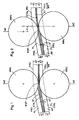
- the position of the web ST of an H-profile HP with respect to the upper and lower flange edges FRO and FRU that of the upper and lower horizontal rollers HWO and HWU and the two Vertical rolls formed nip WSP when the axes of the two pairs of rolls lie in a common vertical axis plane AE change, if the H-profile HP the roll gap WSP at a certain angle of inclination a is fed to the horizontal.
- the distances d1 and d2 of the web center STM of the H-profile HP from the upper flange edges FRO and the lower flange edges FRU before the entry of the H-profile HP into the roll gap WSP are among themselves equal. As they pass through the roll gap WSP change then these distances so that the distance d1 'is greater than the distance d2'. For the center of the web STM, this means that the H-profile has an off-center web ST has.
- the lower horizontal roller HWU becomes from the common vertical axis plane AE out with its vertical axis plane around the Distance v shifted horizontally in the rolling direction WR, then forms when feeding of the H-profile HP with an unchanged angle of inclination a a roll gap WSP 'between the two horizontal rollers HWO and HWU, which causes the center of the web STM is not displaced, as shown in FIG. 1, and the distances d1 and d2 of the center of the web STM from the upper and lower flange edges FRO and FRU remain the same among themselves.
- the fact that the H-profile HP like has shown that the roll gap WSP inclined to the horizontal has, according to experience no longer relevant for the position of the center of the web STM. Furthermore It has been shown that the rolled strand is back in after a short distance the horizontal returns.
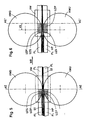
- the vertical rollers VW can move the upper horizontal roller HWO or the lower horizontal roller HWU from the common axis plane AE out, as shown in Fig. 3, here with horizontal displacement of the lower Horizontal roller HWU to either take a position at distance v which the vertical axis plane AEU, here the lower horizontal roller HWU, in one common vertical axis plane or also, (see FIG. 4) in one position be brought with an inclined axis, the angle of inclination aN of Axis the angle between a connecting line of the center axis AM of the two offset horizontal rollers HWO and HWU and the vertical corresponds.
Landscapes
- Engineering & Computer Science (AREA)
- Mechanical Engineering (AREA)
- Metal Rolling (AREA)
Abstract
Description
- Fig. 1
- einen Vertikalschnitt durch die Vorrichtung in schematischer Darstellung,
- Fig. 2
- einen Schnitt entsprechend Fig. 1 mit geänderter Position der Walzen,
- Fig. 3
- einen Teilausschnitt durch eine andere Ausbildung der Vorrichtung in schematischer Darstellung,
- Fig. 4
- einen Teilausschnitt der Darstellung nach Fig. 3 in geänderter Position,
- Fig. 5 und 6
- Teilausschnitte der Darstellung der Vorrichtung in zwei unterschiedlichen Positionen.
- HP
- H-Profil
- ST
- Steg
- FL
- Flansch
- FRO
- (oberer) Flansch-Rand
- FRU
- (unterer) Flansch-Rand
- VW
- Vertikalwalze
- WSP
- Walzspalt
- d1
- Abstand
- d2
- Abstand
- V
- Strecke
- VS
- Strecke
- STM
- Stegmittenebene
- WR
- Walzrichtung
- VL
- Verbindungslinie
- α
- Neigungswinkel
- αN
- Neigungswinkel
- UZF
- Umformzone (Flansch)
- UZS
- Umformzone (Steg)
- AE
- Achsebene
- AEU
- (untere) Achsebene
Claims (8)
- Vorrichtung zur Beeinflussung der Stegposition beim Walzen von Formstahl-Flanschprofilen, insb. H-Trägerprofilen in Universalwalzgerüsten, deren von einem Horizontal- und einem Vertikalwalzenpaar gebildeten Walzspalt profiliertes Walzgut, insbes. H-Profile mit den Flanschrändem auf einem Zuförderer aufstehend, zugeführt wird, bei der die Achsen der Horizontalwalzen und die der Vertikalwalzen in einer gemeinsamen, vertikalen Achsebene angeordnet sind,
dadurch gekennzeichnet,
daß eine oder beide Horizontalwalzen (HWO, HWU) aus ihrer gemeinsamen vertikalen Achsebene (AE) heraus, in oder entgegen der Walzrichtung (WR) verschieb- und festlegbar sind. - Vorrichtung nach Anspruch 1,
dadurch gekennzeichnet,
daß das Vertikalwalzenpaar (VW) um einen vorgegebenen Achs-Schwenkwinkel (αN) aus seiner Vertikalposition heraus kipp- und festlegbar ist. - Vorrichtung nach Anspruch 2,
dadurch gekennzeichnet,
daß der Achs-Schwenkwinkel (αN) des Vertikalwalzenpaares (VW) dem Winkel entspricht, der bei verschobenen Horizontalwalzen (HWO, HWU) zwischen der Verbindungslinie der Achsmitten (AM) beider Horizontalwalzen (HWO, HWU) und der Vertikalen gebildet wird. - Vorrichtung nach Anspruchl,
dadurch gekennzeichnet,
daß der Verschiebeweg der beiden Horizontalwalzen (HWO, HWU) gleich oder kleiner bemessen ist als der Radius der Vertikalwalzen (VW). - Arbeitsverfahren für eine Vorrichtung nach Anspruch 1,
dadurch gekennzeichnet,
daß beide Horizontalwalzen (HWO, HWU) bei unveränderter Positionierung beider Vertikalwalzen (VW) gemeinsam, entgegen der Walzrichtung (WR) horizontal aus der gemeinsamen vertikalen Achsebene (AE) verschoben werden. - Arbeitsverfahren für eine Vorrichtung nach Anspruch 1,
dadurch gekennzeichnet,
daß beide Vertikalwalzen (VW) bei unveränderter Positionierung der beiden Horizontalwalzen (HWO, HWU) gemeinsam in der Walzrichtung (WR) verschoben werden. - Arbeitsverfahren für eine Vorrichtung nach Anspruch 1,
dadurch gekennzeichnet,
daß die obere oder die untere der Horizontalwalzen (HWO, HWU) bei unveränderter Positionierung beider Vertikalwalzen (VW) in oder entgegen der Walzrichtung verschoben wird. - Vorrichtung zur Durchführung der Arbeitsverfahren nach einem oder mehreren der Ansprüche 5 bis 7,
gekennzeichnet durch
vor und ggf. hinter dem Universalwalzgerüst angeordnete, die Abmessungen des, in den Walzspalt ein- bzw. aus diesem auslaufenden Profils erfassenden Meßeinrichtungen, diesen nachgeordnete Recheneinrichtungen, die Korrekturstellwerte für die Verschiebung der Horizontalwalzen und ggf. die Verschwenkung der Vertikalwalzen ermittelt.
Applications Claiming Priority (2)
| Application Number | Priority Date | Filing Date | Title |
|---|---|---|---|
| DE1999158862 DE19958862A1 (de) | 1999-12-07 | 1999-12-07 | Vorrichtung zur Beeinflussung der Stegposition beim Walzen von Formstahl-Flanschprofilen |
| DE19958862 | 1999-12-07 |
Publications (2)
| Publication Number | Publication Date |
|---|---|
| EP1106271A2 true EP1106271A2 (de) | 2001-06-13 |
| EP1106271A3 EP1106271A3 (de) | 2003-01-29 |
Family
ID=7931658
Family Applications (1)
| Application Number | Title | Priority Date | Filing Date |
|---|---|---|---|
| EP00126253A Withdrawn EP1106271A3 (de) | 1999-12-07 | 2000-12-01 | Vorrichtung zur Beeinflussung der Stegposition beim Walzen von Formstahl-Flanschprofilen |
Country Status (2)
| Country | Link |
|---|---|
| EP (1) | EP1106271A3 (de) |
| DE (1) | DE19958862A1 (de) |
Family Cites Families (3)
| Publication number | Priority date | Publication date | Assignee | Title |
|---|---|---|---|---|
| US1163975A (en) * | 1914-07-06 | 1915-12-14 | John C Cromwell | Universal mill. |
| JPS5913921B2 (ja) * | 1980-02-26 | 1984-04-02 | 川崎製鉄株式会社 | ユニバ−サル圧延における上下非対称圧延制御方法 |
| JPS56122601A (en) * | 1980-02-29 | 1981-09-26 | Kawasaki Steel Corp | Universal rolling method |
-
1999
- 1999-12-07 DE DE1999158862 patent/DE19958862A1/de not_active Withdrawn
-
2000
- 2000-12-01 EP EP00126253A patent/EP1106271A3/de not_active Withdrawn
Also Published As
| Publication number | Publication date |
|---|---|
| DE19958862A1 (de) | 2001-06-13 |
| EP1106271A3 (de) | 2003-01-29 |
Similar Documents
| Publication | Publication Date | Title |
|---|---|---|
| EP0049798B1 (de) | Walzwerk | |
| DE69710817T2 (de) | Walzverfahren und Walzwerk für Band zur Reduzierung der Kantenanschärfung | |
| DE19719318C2 (de) | Verfahren zur Beeinflussung der Bandkontur im Kantenbereich eines Walzenbandes | |
| EP0560091A1 (de) | Verfahren und Vorrichtung zum Richten von H-förmigen Trägerprofilen | |
| DE19520541A1 (de) | Verfahren und Vorrichtung zum Korrigieren von gewalzten, in der Bandebene horizontal gebogenen Metallbändern, insbesondere von Metallbändern mit einer Banddicke von 0,5 mm bis 2,0 mm | |
| EP0329132B1 (de) | Fertigwalzverfahren für Profile | |
| DE3780453T2 (de) | Walze zum stauchen von flanschen eines walzprofils. | |
| DE2437545C3 (de) | Verfahren zum Walzen von Metallstäben | |
| DE69108373T2 (de) | Führungsvorrichtung für das Walzen von Profilen. | |
| DE4413913C2 (de) | Verfahren zum Verhindern eines Faltungsstaus beim Walzen von Metallband | |
| DE1809260A1 (de) | Walzwerk | |
| DE29980239U1 (de) | Walzwerk mit zweidimensional gesteuerter Walzendurchbiegung | |
| DE3245031C2 (de) | ||
| EP0703014B1 (de) | Verfahren zum Walzen von Hohlblöcken auf einem Asselwalzwerk | |
| DE4308743C2 (de) | Walzgerüst | |
| EP0757599B1 (de) | Verfahren und vorrichtung zum walzen von trägern aus vorprofilen | |
| DE19958862A1 (de) | Vorrichtung zur Beeinflussung der Stegposition beim Walzen von Formstahl-Flanschprofilen | |
| DE19953138B4 (de) | Verfahren und Rollenrichtmaschine zum Richten eines Stabes oder Profils | |
| DE4407981A1 (de) | Verfahren und Vorrichtung zur geregelten Bildung von Walzgut-Schlingen | |
| EP1669141B1 (de) | Verfahren zur Regelung des Querschnitts von aus einer Drahtwalzstrasse austretenden Drähten und Drahtwalzstrasse | |
| DE3638331C2 (de) | Walzgerüst zum Walzen von Flachmaterial mit einem Paar von axial verschiebbaren Arbeitswalzen | |
| EP1112783A2 (de) | Walzverfahren für ein Profil, insbesondere ein Flanschprofil, und hiermit korrespondierendes Universalwalzgerüst | |
| EP0181474A2 (de) | Sechs-Walzen-Walzwerk | |
| EP1128917A1 (de) | Walzgerüst mit stütz- und arbeitswalzen | |
| DE2808993C2 (de) | Vorrichtung an einem Walzgerüst zur Regelung der Ebenheit von Walzgut |
Legal Events
| Date | Code | Title | Description |
|---|---|---|---|
| PUAI | Public reference made under article 153(3) epc to a published international application that has entered the european phase |
Free format text: ORIGINAL CODE: 0009012 |
|
| 17P | Request for examination filed |
Effective date: 20001215 |
|
| AK | Designated contracting states |
Kind code of ref document: A2 Designated state(s): AT BE CH CY DE DK ES FI FR GB GR IE IT LI LU MC NL PT SE TR |
|
| AX | Request for extension of the european patent |
Free format text: AL;LT;LV;MK;RO;SI |
|
| PUAL | Search report despatched |
Free format text: ORIGINAL CODE: 0009013 |
|
| RIC1 | Information provided on ipc code assigned before grant |
Free format text: 7B 21B 1/08 A, 7B 21B 13/08 B |
|
| AK | Designated contracting states |
Designated state(s): AT BE CH CY DE DK ES FI FR GB GR IE IT LI LU MC NL PT SE TR |
|
| AX | Request for extension of the european patent |
Extension state: AL LT LV MK RO SI |
|
| AKX | Designation fees paid | ||
| REG | Reference to a national code |
Ref country code: DE Ref legal event code: 8566 |
|
| STAA | Information on the status of an ep patent application or granted ep patent |
Free format text: STATUS: THE APPLICATION IS DEEMED TO BE WITHDRAWN |
|
| 18D | Application deemed to be withdrawn |
Effective date: 20030730 |