EP1094763B1 - Stent-katheter-anordnung - Google Patents
Stent-katheter-anordnung Download PDFInfo
- Publication number
- EP1094763B1 EP1094763B1 EP00936706A EP00936706A EP1094763B1 EP 1094763 B1 EP1094763 B1 EP 1094763B1 EP 00936706 A EP00936706 A EP 00936706A EP 00936706 A EP00936706 A EP 00936706A EP 1094763 B1 EP1094763 B1 EP 1094763B1
- Authority
- EP
- European Patent Office
- Prior art keywords
- stent
- balloon
- expandable
- section
- catheter
- Prior art date
- Legal status (The legal status is an assumption and is not a legal conclusion. Google has not performed a legal analysis and makes no representation as to the accuracy of the status listed.)
- Expired - Lifetime
Links
Images
Classifications
-
- A—HUMAN NECESSITIES
- A61—MEDICAL OR VETERINARY SCIENCE; HYGIENE
- A61F—FILTERS IMPLANTABLE INTO BLOOD VESSELS; PROSTHESES; DEVICES PROVIDING PATENCY TO, OR PREVENTING COLLAPSING OF, TUBULAR STRUCTURES OF THE BODY, e.g. STENTS; ORTHOPAEDIC, NURSING OR CONTRACEPTIVE DEVICES; FOMENTATION; TREATMENT OR PROTECTION OF EYES OR EARS; BANDAGES, DRESSINGS OR ABSORBENT PADS; FIRST-AID KITS
- A61F2/00—Filters implantable into blood vessels; Prostheses, i.e. artificial substitutes or replacements for parts of the body; Appliances for connecting them with the body; Devices providing patency to, or preventing collapsing of, tubular structures of the body, e.g. stents
- A61F2/95—Instruments specially adapted for placement or removal of stents or stent-grafts
- A61F2/958—Inflatable balloons for placing stents or stent-grafts
-
- A—HUMAN NECESSITIES
- A61—MEDICAL OR VETERINARY SCIENCE; HYGIENE
- A61F—FILTERS IMPLANTABLE INTO BLOOD VESSELS; PROSTHESES; DEVICES PROVIDING PATENCY TO, OR PREVENTING COLLAPSING OF, TUBULAR STRUCTURES OF THE BODY, e.g. STENTS; ORTHOPAEDIC, NURSING OR CONTRACEPTIVE DEVICES; FOMENTATION; TREATMENT OR PROTECTION OF EYES OR EARS; BANDAGES, DRESSINGS OR ABSORBENT PADS; FIRST-AID KITS
- A61F2250/00—Special features of prostheses classified in groups A61F2/00 - A61F2/26 or A61F2/82 or A61F9/00 or A61F11/00 or subgroups thereof
- A61F2250/0014—Special features of prostheses classified in groups A61F2/00 - A61F2/26 or A61F2/82 or A61F9/00 or A61F11/00 or subgroups thereof having different values of a given property or geometrical feature, e.g. mechanical property or material property, at different locations within the same prosthesis
- A61F2250/0037—Special features of prostheses classified in groups A61F2/00 - A61F2/26 or A61F2/82 or A61F9/00 or A61F11/00 or subgroups thereof having different values of a given property or geometrical feature, e.g. mechanical property or material property, at different locations within the same prosthesis differing in height or in length
-
- A—HUMAN NECESSITIES
- A61—MEDICAL OR VETERINARY SCIENCE; HYGIENE
- A61M—DEVICES FOR INTRODUCING MEDIA INTO, OR ONTO, THE BODY; DEVICES FOR TRANSDUCING BODY MEDIA OR FOR TAKING MEDIA FROM THE BODY; DEVICES FOR PRODUCING OR ENDING SLEEP OR STUPOR
- A61M25/00—Catheters; Hollow probes
- A61M25/10—Balloon catheters
- A61M25/1002—Balloon catheters characterised by balloon shape
Definitions
- the invention relates to a stent-catheter arrangement according to the Preamble of claim 1.
- Such an arrangement is known from EP 0.779 062 A1 and is used, for example, to stenosis in Widen blood vessels.
- the on the expandable balloon of the stent-catheter assembly Stent inserted into a patient's blood vessel and with Using a guide wire to advance into the area of the stenosis.
- the balloon is filled with a suitable medium widened in the catheter, so that the The stent expands radially until the stenosis reaches the desired level is expanded.
- the balloon is deflated and the catheter assembly can be taken from the patient's body whereby the stent remains within the stenosis and this stays in the expanded position.
- vascular implant is known that from a mountable from the inside to a vessel wall Anchoring part and one arranged in the cavity of the vessel Functional part exists.
- the functional part is up to Longitudinal center axis tapered and can with a Coating should be provided so that it is permanently effective Form vascular occlusions.
- the stent-catheter arrangement according to the invention has a catheter that includes an expandable balloon that at least in one of his areas, usually roughly his Middle area, has a less expandable section.
- the balloon formed in this way is used in the usual way Stent put on, for example crimped, with a flow-impermeable covering is provided.
- This arrangement is inserted into a patient's vessel and the balloon is expanded, there remains one remaining in the vessel Formation of the stent, which has two areas, by means of which the stent is fixed in the vessel. Between these both areas of fixation result when the balloon is expanded a throttling section because the stent is in this area the smaller expandable area of the balloon.
- the Throttle range can vary depending on the treatment case be formed, but in any case has a volume that one throttled, but sufficient blood flow allowed.
- the Throttle area of the stent is a gradually tapering Area so that swirls of blood flow at least can be largely avoided.
- the stent can be encased using a suitable, body-compatible Foil are caused, for example PTFE material can exist.
- the smaller expandable area of the balloon can be reduced by a appropriate stiffening of the balloon material in this section caused, for example, integrated in the balloon material Stiffeners or even on the balloon material in this Area stiffeners applied, such as a preferably stiffening ring stuck on can.
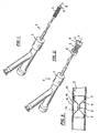
- the Arrangement 1 can be a commercially available catheter 2 have with an expandable balloon 3. On the balloon 3 is not expanded in the representation according to FIG. 1 State a stent 4 is placed, for example crimped on.
- the balloon 3 of the stent-catheter arrangement according to the invention has a less expandable section 5, which is shown in Fig. 2 is visible, which shows the overall expanded state of the Balloons 3 represents.
- the less expandable section 5 lies between two fully expandable sections 11 and 12.
- Fig. 3 shows this state.
- 3 is schematically simplified in Representation of a patient's vessel G shown in which a stent 4 according to the invention is arranged.
- the balloon 3 has two fixing sections 7 and 8 result, with the help of which the stent 4 in the vessel G, that is whose inner wall I is fixed.
- a throttle region 9 Between the fixation areas 7 and 8 is a throttle region 9, which in its Cross section clearly compared to the fixing sections 7 and 8 is reduced. The reduction results from the less expandable section 5 of the balloon 3 when expanding of the balloon 3, as is illustrated in FIG. 2.
- FIG. 3 also shows a covering in a simplified representation (Sheath) 10, which is the entire stent structure, which is usually is a web structure, covered so that in itself blood-permeable bridge structure of the stent 4 according to the invention is made impervious to liquids.
- Sheath a simplified representation
Landscapes
- Health & Medical Sciences (AREA)
- Engineering & Computer Science (AREA)
- Biomedical Technology (AREA)
- Life Sciences & Earth Sciences (AREA)
- General Health & Medical Sciences (AREA)
- Transplantation (AREA)
- Heart & Thoracic Surgery (AREA)
- Vascular Medicine (AREA)
- Cardiology (AREA)
- Animal Behavior & Ethology (AREA)
- Oral & Maxillofacial Surgery (AREA)
- Public Health (AREA)
- Veterinary Medicine (AREA)
- Media Introduction/Drainage Providing Device (AREA)
- Prostheses (AREA)
- Materials For Medical Uses (AREA)
- External Artificial Organs (AREA)
- Laser Surgery Devices (AREA)
Description
Claims (7)
- Stent-Katheter-Anordnung (1)dadurch gekennzeichnet,mit einem Katheter (2), der einen aufweitbaren Ballon (3) mit einem ersten vollständig aufweitbaren Abschnitt (11) und einem zweiten vollständig aufweitbaren Abschnitt (12) und einem zwischen diesen angeordneten reduziert aufweitbaren Abschnitt (5) aufweist; undmit einem Stent (4), der auf dem aufweitbaren Ballon (3) platzierbar ist,dass der Stent (4) mit einer flüssigkeitsundurchlässigen Umhüllung (10) zur Bildung eines Drosselabschnittes (9) zwischen zwei Fixierungsabschnitten (7, 8) versehen ist, wobei der Drosselabschnitt (9) des Stents (4) im in einem Gefäß (G) implantierten Zustand einen Abstand zu der Innenwandung (I) des Gefäßes (G) einnimmt.
- Stent-Katheter-Anordnung nach Anspruch 1, dadurch gekennzeichnet, daß die Umhüllung (10) eine Folie oder ein Mantel ist.
- Stent-Katheter-Anordnung nach Anspruch 2, dadurch gekennzeichnet, daß die Folie beziehungsweise der Mantel aus körperverträglichem Material besteht.
- Stent-Katheter-Anordnung nach Anspruch 2 oder 3, dadurch gekennzeichnet, daß die Folie beziehungsweise der Mantel aus biologischem Material, aus Polymer-Material, aus metallischem Material, keramischem Material oder Elastomer-Material besteht.
- Stent-Katheter-Anordnung nach einem der Ansprüche 1 bis 3, dadurch gekennzeichnet, daß der reduziert aufweitbare Abschnitt (5) des Ballons (3) aus versteiftem Ballon-Material besteht.
- Stent-Katheter-Anordnung nach einem der Ansprüche 1 bis 3, dadurch gekennzeichnet, daß der reduziert aufweitbare Abschnitt (5) des Ballons (3) durch ein auf dem aufweitbaren Material des Ballons aufgebrachtes Versteifungselement gebildet ist.
- Stent-Katheter-Anordnung nach einem der Ansprüche 1 bis 5, dadurch gekennzeichnet, daß der reduziert aufweitbare Abschnitt (5) des Ballons (3) im Zuge der Ballonherstellung erzeugbar ist.
Applications Claiming Priority (3)
| Application Number | Priority Date | Filing Date | Title |
|---|---|---|---|
| DE29907827U DE29907827U1 (de) | 1999-05-03 | 1999-05-03 | Stent-Katheter-Anordnung |
| DE29907827U | 1999-05-03 | ||
| PCT/EP2000/003971 WO2000066033A1 (de) | 1999-05-03 | 2000-05-03 | Stent-katheter-anordnung |
Publications (2)
| Publication Number | Publication Date |
|---|---|
| EP1094763A1 EP1094763A1 (de) | 2001-05-02 |
| EP1094763B1 true EP1094763B1 (de) | 2004-11-17 |
Family
ID=8073032
Family Applications (1)
| Application Number | Title | Priority Date | Filing Date |
|---|---|---|---|
| EP00936706A Expired - Lifetime EP1094763B1 (de) | 1999-05-03 | 2000-05-03 | Stent-katheter-anordnung |
Country Status (6)
| Country | Link |
|---|---|
| EP (1) | EP1094763B1 (de) |
| JP (1) | JP4191899B2 (de) |
| AT (1) | ATE282375T1 (de) |
| AU (1) | AU5211000A (de) |
| DE (2) | DE29907827U1 (de) |
| WO (1) | WO2000066033A1 (de) |
Families Citing this family (3)
| Publication number | Priority date | Publication date | Assignee | Title |
|---|---|---|---|---|
| WO2004103223A1 (en) * | 2003-05-20 | 2004-12-02 | The Cleveland Clinic Foundation | Apparatus and methods for repair of a cardiac valve |
| DE10335649A1 (de) * | 2003-07-30 | 2005-02-24 | Jotec Gmbh | Flechtstent zur Implantation in ein Blutgefäß |
| CN113350670B (zh) * | 2021-07-22 | 2025-12-09 | 苏州鼎科医疗技术股份有限公司 | 一种具有单向阀的灌注球囊导管 |
Family Cites Families (15)
| Publication number | Priority date | Publication date | Assignee | Title |
|---|---|---|---|---|
| US4798586A (en) | 1987-04-09 | 1989-01-17 | Cordis Corporation | Method and apparatus for aiding dilatation catheterization |
| US5181911A (en) | 1991-04-22 | 1993-01-26 | Shturman Technologies, Inc. | Helical balloon perfusion angioplasty catheter |
| US5843116A (en) * | 1996-05-02 | 1998-12-01 | Cardiovascular Dynamics, Inc. | Focalized intraluminal balloons |
| EP0689805B1 (de) * | 1994-06-27 | 2003-05-28 | Corvita Corporation | Bistabile luminale Transplantat-Endoprothesen |
| DE19509464C1 (de) * | 1995-03-20 | 1996-06-27 | Horst J Dr Med Jaeger | Gefäßimplantat |
| RU2157146C2 (ru) * | 1995-06-13 | 2000-10-10 | ВИЛЬЯМ КУК Европа, A/S | Устройство для имплантации в сосудах и полых органах (его варианты) |
| US5591195A (en) | 1995-10-30 | 1997-01-07 | Taheri; Syde | Apparatus and method for engrafting a blood vessel |
| NL1001878C2 (nl) * | 1995-12-12 | 1997-06-17 | Cordis Europ | Werkwijze voor het vervaardigen van een stent en een buisvormig element en katheter daarvoor. |
| US5695498A (en) | 1996-02-28 | 1997-12-09 | Numed, Inc. | Stent implantation system |
| WO1998002112A1 (fr) * | 1996-07-12 | 1998-01-22 | Alain Fouere | Gaine filtre extensible a usage chirurgical pour veine cave ou gros vaisseaux sanguins |
| GB9616267D0 (en) * | 1996-08-02 | 1996-09-11 | Ranier Ltd | Balloon catheter |
| DE19713214A1 (de) | 1997-03-28 | 1998-12-10 | Ruebben Alexander Dr Med | Covered Stent zur verlängerten Offenhaltung von Hohlorganen oder der Behandlung von Gefäßaneurysmen |
| US6007575A (en) | 1997-06-06 | 1999-12-28 | Samuels; Shaun Laurence Wilkie | Inflatable intraluminal stent and method for affixing same within the human body |
| FR2768611B1 (fr) * | 1997-09-19 | 2000-07-28 | Patrice Bergeron | Procede pour l'angioplastie d'anevrismes, protheses intraluminales et ballonnets pour la mise en oeuvre dudit procede |
| DE19801076C1 (de) | 1998-01-14 | 1999-06-24 | Voelker Wolfram Priv Doz Dr Me | Expansionskatheter für die Bypass-Chirurgie |
-
1999
- 1999-05-03 DE DE29907827U patent/DE29907827U1/de not_active Expired - Lifetime
-
2000
- 2000-05-03 AU AU52110/00A patent/AU5211000A/en not_active Abandoned
- 2000-05-03 JP JP2000614920A patent/JP4191899B2/ja not_active Expired - Fee Related
- 2000-05-03 DE DE50008656T patent/DE50008656D1/de not_active Expired - Lifetime
- 2000-05-03 WO PCT/EP2000/003971 patent/WO2000066033A1/de not_active Ceased
- 2000-05-03 EP EP00936706A patent/EP1094763B1/de not_active Expired - Lifetime
- 2000-05-03 AT AT00936706T patent/ATE282375T1/de not_active IP Right Cessation
Also Published As
| Publication number | Publication date |
|---|---|
| ATE282375T1 (de) | 2004-12-15 |
| JP4191899B2 (ja) | 2008-12-03 |
| DE50008656D1 (de) | 2004-12-23 |
| EP1094763A1 (de) | 2001-05-02 |
| JP2002542881A (ja) | 2002-12-17 |
| WO2000066033A1 (de) | 2000-11-09 |
| DE29907827U1 (de) | 1999-07-22 |
| AU5211000A (en) | 2000-11-17 |
Similar Documents
| Publication | Publication Date | Title |
|---|---|---|
| DE69502817T2 (de) | Aufweitbarer stent | |
| DE69706107T2 (de) | Mehrzelliger Stent mit Zellen von unterschiedlichen Eigenschaften | |
| DE69635951T2 (de) | Doppelt unterstütztes intraluminales transplantat | |
| DE60221085T2 (de) | Einsatz für einen Stent | |
| EP1293177B1 (de) | Stent | |
| DE69530744T2 (de) | Stentkatheter und verfahren zur herstellung eines stentkatheters | |
| DE69825162T2 (de) | Intravaskulärer stent mit einer ablenkvorrichtung | |
| DE69717793T2 (de) | Dilators- und einführersanordnung | |
| EP0800800B1 (de) | Stent zur transluminalen Implantation in Hohlorgane | |
| DE69731514T2 (de) | Expandierbarer Stent | |
| EP0436154B1 (de) | Transcutaner Implantatkatheter | |
| DE69108423T2 (de) | Aufblasbarer Dilatator. | |
| DE60212048T2 (de) | Katheter mit verbesserter distaler Schubfähigkeit | |
| DE69121592T2 (de) | Resektierbarer selbstausbreitender stent | |
| DE69725120T2 (de) | Spreizbarer stent | |
| DE69532267T2 (de) | Katheter für Stentimplantation | |
| DE69722348T2 (de) | Katheter mit aufspreizbarem Schaft | |
| DE69734692T2 (de) | Vorrichtung zur Implantation einer Prothese in einem Körperkanal | |
| DE69637173T2 (de) | Aufweitbarer endovaskulärer Stent | |
| DE69534065T2 (de) | Katheter mit verstärktem länglichem querschnitt | |
| DE69512607T2 (de) | Ballonkatheter | |
| EP2263606B1 (de) | Kompakter Stent | |
| DE69407984T2 (de) | Tubulares dehnbares glied für eine intraluminale endoprothese, intraluminale endoprothese und verfahren zur herstellung | |
| EP0884028B1 (de) | Kombination aus einem radial aufweitbaren Stent zur Implantierung in ein Körpergefäss im Bereich einer Gefässverzweigung und einem Ballonkatheter | |
| EP0730848B1 (de) | Stent zum Anordnen in einer Körperröhre |
Legal Events
| Date | Code | Title | Description |
|---|---|---|---|
| PUAI | Public reference made under article 153(3) epc to a published international application that has entered the european phase |
Free format text: ORIGINAL CODE: 0009012 |
|
| 17P | Request for examination filed |
Effective date: 20001207 |
|
| AK | Designated contracting states |
Kind code of ref document: A1 Designated state(s): AT BE CH CY DE DK ES FI FR GB GR IE IT LI LU MC NL PT SE |
|
| AX | Request for extension of the european patent |
Free format text: AL;LT;LV;MK;RO;SI |
|
| 17Q | First examination report despatched |
Effective date: 20031007 |
|
| RAP1 | Party data changed (applicant data changed or rights of an application transferred) |
Owner name: ABBOTT LABORATORIES VASCULAR ENTERPRISES LIMITED |
|
| GRAP | Despatch of communication of intention to grant a patent |
Free format text: ORIGINAL CODE: EPIDOSNIGR1 |
|
| GRAS | Grant fee paid |
Free format text: ORIGINAL CODE: EPIDOSNIGR3 |
|
| GRAA | (expected) grant |
Free format text: ORIGINAL CODE: 0009210 |
|
| AK | Designated contracting states |
Kind code of ref document: B1 Designated state(s): AT BE CH CY DE DK ES FI FR GB GR IE IT LI LU MC NL PT SE |
|
| PG25 | Lapsed in a contracting state [announced via postgrant information from national office to epo] |
Ref country code: IT Free format text: LAPSE BECAUSE OF FAILURE TO SUBMIT A TRANSLATION OF THE DESCRIPTION OR TO PAY THE FEE WITHIN THE PRESCRIBED TIME-LIMIT;WARNING: LAPSES OF ITALIAN PATENTS WITH EFFECTIVE DATE BEFORE 2007 MAY HAVE OCCURRED AT ANY TIME BEFORE 2007. THE CORRECT EFFECTIVE DATE MAY BE DIFFERENT FROM THE ONE RECORDED. Effective date: 20041117 Ref country code: FR Free format text: LAPSE BECAUSE OF FAILURE TO SUBMIT A TRANSLATION OF THE DESCRIPTION OR TO PAY THE FEE WITHIN THE PRESCRIBED TIME-LIMIT Effective date: 20041117 Ref country code: FI Free format text: LAPSE BECAUSE OF FAILURE TO SUBMIT A TRANSLATION OF THE DESCRIPTION OR TO PAY THE FEE WITHIN THE PRESCRIBED TIME-LIMIT Effective date: 20041117 Ref country code: GB Free format text: LAPSE BECAUSE OF FAILURE TO SUBMIT A TRANSLATION OF THE DESCRIPTION OR TO PAY THE FEE WITHIN THE PRESCRIBED TIME-LIMIT Effective date: 20041117 |
|
| REG | Reference to a national code |
Ref country code: GB Ref legal event code: FG4D Free format text: NOT ENGLISH |
|
| REG | Reference to a national code |
Ref country code: CH Ref legal event code: EP |
|
| REG | Reference to a national code |
Ref country code: IE Ref legal event code: FG4D Free format text: GERMAN |
|
| REF | Corresponds to: |
Ref document number: 50008656 Country of ref document: DE Date of ref document: 20041223 Kind code of ref document: P |
|
| PG25 | Lapsed in a contracting state [announced via postgrant information from national office to epo] |
Ref country code: SE Free format text: LAPSE BECAUSE OF FAILURE TO SUBMIT A TRANSLATION OF THE DESCRIPTION OR TO PAY THE FEE WITHIN THE PRESCRIBED TIME-LIMIT Effective date: 20050217 Ref country code: DK Free format text: LAPSE BECAUSE OF FAILURE TO SUBMIT A TRANSLATION OF THE DESCRIPTION OR TO PAY THE FEE WITHIN THE PRESCRIBED TIME-LIMIT Effective date: 20050217 Ref country code: GR Free format text: LAPSE BECAUSE OF FAILURE TO SUBMIT A TRANSLATION OF THE DESCRIPTION OR TO PAY THE FEE WITHIN THE PRESCRIBED TIME-LIMIT Effective date: 20050217 |
|
| PG25 | Lapsed in a contracting state [announced via postgrant information from national office to epo] |
Ref country code: ES Free format text: LAPSE BECAUSE OF FAILURE TO SUBMIT A TRANSLATION OF THE DESCRIPTION OR TO PAY THE FEE WITHIN THE PRESCRIBED TIME-LIMIT Effective date: 20050228 |
|
| PG25 | Lapsed in a contracting state [announced via postgrant information from national office to epo] |
Ref country code: LU Free format text: LAPSE BECAUSE OF NON-PAYMENT OF DUE FEES Effective date: 20050503 Ref country code: AT Free format text: LAPSE BECAUSE OF NON-PAYMENT OF DUE FEES Effective date: 20050503 Ref country code: CY Free format text: LAPSE BECAUSE OF FAILURE TO SUBMIT A TRANSLATION OF THE DESCRIPTION OR TO PAY THE FEE WITHIN THE PRESCRIBED TIME-LIMIT Effective date: 20050503 |
|
| PG25 | Lapsed in a contracting state [announced via postgrant information from national office to epo] |
Ref country code: CH Free format text: LAPSE BECAUSE OF NON-PAYMENT OF DUE FEES Effective date: 20050531 Ref country code: BE Free format text: LAPSE BECAUSE OF NON-PAYMENT OF DUE FEES Effective date: 20050531 Ref country code: MC Free format text: LAPSE BECAUSE OF NON-PAYMENT OF DUE FEES Effective date: 20050531 Ref country code: LI Free format text: LAPSE BECAUSE OF NON-PAYMENT OF DUE FEES Effective date: 20050531 |
|
| GBV | Gb: ep patent (uk) treated as always having been void in accordance with gb section 77(7)/1977 [no translation filed] |
Effective date: 20041117 |
|
| PLBE | No opposition filed within time limit |
Free format text: ORIGINAL CODE: 0009261 |
|
| STAA | Information on the status of an ep patent application or granted ep patent |
Free format text: STATUS: NO OPPOSITION FILED WITHIN TIME LIMIT |
|
| 26N | No opposition filed |
Effective date: 20050818 |
|
| BERE | Be: lapsed |
Owner name: ABBOTT LABORATORIES VASCULAR ENTERPRISES LIMITED Effective date: 20050531 |
|
| EN | Fr: translation not filed | ||
| REG | Reference to a national code |
Ref country code: CH Ref legal event code: PL |
|
| BERE | Be: lapsed |
Owner name: *ABBOTT LABORATORIES VASCULAR ENTERPRISES LTD Effective date: 20050531 |
|
| PG25 | Lapsed in a contracting state [announced via postgrant information from national office to epo] |
Ref country code: PT Free format text: LAPSE BECAUSE OF NON-PAYMENT OF DUE FEES Effective date: 20050417 |
|
| PGFP | Annual fee paid to national office [announced via postgrant information from national office to epo] |
Ref country code: NL Payment date: 20160506 Year of fee payment: 17 |
|
| PGFP | Annual fee paid to national office [announced via postgrant information from national office to epo] |
Ref country code: IE Payment date: 20160426 Year of fee payment: 17 |
|
| REG | Reference to a national code |
Ref country code: NL Ref legal event code: MM Effective date: 20170601 |
|
| REG | Reference to a national code |
Ref country code: IE Ref legal event code: MM4A |
|
| PG25 | Lapsed in a contracting state [announced via postgrant information from national office to epo] |
Ref country code: NL Free format text: LAPSE BECAUSE OF NON-PAYMENT OF DUE FEES Effective date: 20170601 |
|
| PG25 | Lapsed in a contracting state [announced via postgrant information from national office to epo] |
Ref country code: IE Free format text: LAPSE BECAUSE OF NON-PAYMENT OF DUE FEES Effective date: 20170503 |
|
| PGFP | Annual fee paid to national office [announced via postgrant information from national office to epo] |
Ref country code: DE Payment date: 20190412 Year of fee payment: 20 |
|
| REG | Reference to a national code |
Ref country code: DE Ref legal event code: R071 Ref document number: 50008656 Country of ref document: DE |