EP1091846B1 - Apparatus that clamps an end member to a casing - Google Patents
Apparatus that clamps an end member to a casing Download PDFInfo
- Publication number
- EP1091846B1 EP1091846B1 EP99923632A EP99923632A EP1091846B1 EP 1091846 B1 EP1091846 B1 EP 1091846B1 EP 99923632 A EP99923632 A EP 99923632A EP 99923632 A EP99923632 A EP 99923632A EP 1091846 B1 EP1091846 B1 EP 1091846B1
- Authority
- EP
- European Patent Office
- Prior art keywords
- clamping
- casing
- piston
- countersurfaces
- pushing
- Prior art date
- Legal status (The legal status is an assumption and is not a legal conclusion. Google has not performed a legal analysis and makes no representation as to the accuracy of the status listed.)
- Expired - Lifetime
Links
- 238000007789 sealing Methods 0.000 claims abstract description 11
- 239000000463 material Substances 0.000 claims description 10
- 230000033001 locomotion Effects 0.000 claims description 8
- 238000000576 coating method Methods 0.000 description 8
- 238000010438 heat treatment Methods 0.000 description 7
- 239000011248 coating agent Substances 0.000 description 6
- 238000004806 packaging method and process Methods 0.000 description 5
- 239000007788 liquid Substances 0.000 description 4
- 239000002184 metal Substances 0.000 description 3
- 238000007493 shaping process Methods 0.000 description 3
- 230000000694 effects Effects 0.000 description 2
- 238000005304 joining Methods 0.000 description 2
- 238000003825 pressing Methods 0.000 description 2
- 229910045601 alloy Inorganic materials 0.000 description 1
- 239000000956 alloy Substances 0.000 description 1
- 238000007664 blowing Methods 0.000 description 1
- 238000001816 cooling Methods 0.000 description 1
- 238000005520 cutting process Methods 0.000 description 1
- 230000001419 dependent effect Effects 0.000 description 1
- 238000004519 manufacturing process Methods 0.000 description 1
- 238000000034 method Methods 0.000 description 1
- 238000007639 printing Methods 0.000 description 1
- 239000002994 raw material Substances 0.000 description 1
- 239000000126 substance Substances 0.000 description 1
Images


Classifications
-
- B—PERFORMING OPERATIONS; TRANSPORTING
- B65—CONVEYING; PACKING; STORING; HANDLING THIN OR FILAMENTARY MATERIAL
- B65B—MACHINES, APPARATUS OR DEVICES FOR, OR METHODS OF, PACKAGING ARTICLES OR MATERIALS; UNPACKING
- B65B7/00—Closing containers or receptacles after filling
- B65B7/16—Closing semi-rigid or rigid containers or receptacles not deformed by, or not taking-up shape of, contents, e.g. boxes or cartons
- B65B7/28—Closing semi-rigid or rigid containers or receptacles not deformed by, or not taking-up shape of, contents, e.g. boxes or cartons by applying separate preformed closures, e.g. lids, covers
- B65B7/2842—Securing closures on containers
- B65B7/2892—Securing closures on containers by deformation of the container rim
-
- B—PERFORMING OPERATIONS; TRANSPORTING
- B29—WORKING OF PLASTICS; WORKING OF SUBSTANCES IN A PLASTIC STATE IN GENERAL
- B29C—SHAPING OR JOINING OF PLASTICS; SHAPING OF MATERIAL IN A PLASTIC STATE, NOT OTHERWISE PROVIDED FOR; AFTER-TREATMENT OF THE SHAPED PRODUCTS, e.g. REPAIRING
- B29C65/00—Joining or sealing of preformed parts, e.g. welding of plastics materials; Apparatus therefor
- B29C65/02—Joining or sealing of preformed parts, e.g. welding of plastics materials; Apparatus therefor by heating, with or without pressure
- B29C65/10—Joining or sealing of preformed parts, e.g. welding of plastics materials; Apparatus therefor by heating, with or without pressure using hot gases (e.g. combustion gases) or flames coming in contact with at least one of the parts to be joined
-
- B—PERFORMING OPERATIONS; TRANSPORTING
- B29—WORKING OF PLASTICS; WORKING OF SUBSTANCES IN A PLASTIC STATE IN GENERAL
- B29C—SHAPING OR JOINING OF PLASTICS; SHAPING OF MATERIAL IN A PLASTIC STATE, NOT OTHERWISE PROVIDED FOR; AFTER-TREATMENT OF THE SHAPED PRODUCTS, e.g. REPAIRING
- B29C65/00—Joining or sealing of preformed parts, e.g. welding of plastics materials; Apparatus therefor
- B29C65/78—Means for handling the parts to be joined, e.g. for making containers or hollow articles, e.g. means for handling sheets, plates, web-like materials, tubular articles, hollow articles or elements to be joined therewith; Means for discharging the joined articles from the joining apparatus
- B29C65/7858—Means for handling the parts to be joined, e.g. for making containers or hollow articles, e.g. means for handling sheets, plates, web-like materials, tubular articles, hollow articles or elements to be joined therewith; Means for discharging the joined articles from the joining apparatus characterised by the feeding movement of the parts to be joined
- B29C65/7879—Means for handling the parts to be joined, e.g. for making containers or hollow articles, e.g. means for handling sheets, plates, web-like materials, tubular articles, hollow articles or elements to be joined therewith; Means for discharging the joined articles from the joining apparatus characterised by the feeding movement of the parts to be joined said parts to be joined moving in a closed path, e.g. a rectangular path
- B29C65/7882—Means for handling the parts to be joined, e.g. for making containers or hollow articles, e.g. means for handling sheets, plates, web-like materials, tubular articles, hollow articles or elements to be joined therewith; Means for discharging the joined articles from the joining apparatus characterised by the feeding movement of the parts to be joined said parts to be joined moving in a closed path, e.g. a rectangular path said parts to be joined moving in a circular path
-
- B—PERFORMING OPERATIONS; TRANSPORTING
- B29—WORKING OF PLASTICS; WORKING OF SUBSTANCES IN A PLASTIC STATE IN GENERAL
- B29C—SHAPING OR JOINING OF PLASTICS; SHAPING OF MATERIAL IN A PLASTIC STATE, NOT OTHERWISE PROVIDED FOR; AFTER-TREATMENT OF THE SHAPED PRODUCTS, e.g. REPAIRING
- B29C66/00—General aspects of processes or apparatus for joining preformed parts
- B29C66/01—General aspects dealing with the joint area or with the area to be joined
- B29C66/05—Particular design of joint configurations
- B29C66/10—Particular design of joint configurations particular design of the joint cross-sections
- B29C66/12—Joint cross-sections combining only two joint-segments; Tongue and groove joints; Tenon and mortise joints; Stepped joint cross-sections
- B29C66/124—Tongue and groove joints
- B29C66/1244—Tongue and groove joints characterised by the male part, i.e. the part comprising the tongue
- B29C66/12441—Tongue and groove joints characterised by the male part, i.e. the part comprising the tongue being a single wall
-
- B—PERFORMING OPERATIONS; TRANSPORTING
- B29—WORKING OF PLASTICS; WORKING OF SUBSTANCES IN A PLASTIC STATE IN GENERAL
- B29C—SHAPING OR JOINING OF PLASTICS; SHAPING OF MATERIAL IN A PLASTIC STATE, NOT OTHERWISE PROVIDED FOR; AFTER-TREATMENT OF THE SHAPED PRODUCTS, e.g. REPAIRING
- B29C66/00—General aspects of processes or apparatus for joining preformed parts
- B29C66/01—General aspects dealing with the joint area or with the area to be joined
- B29C66/05—Particular design of joint configurations
- B29C66/20—Particular design of joint configurations particular design of the joint lines, e.g. of the weld lines
- B29C66/24—Particular design of joint configurations particular design of the joint lines, e.g. of the weld lines said joint lines being closed or non-straight
- B29C66/242—Particular design of joint configurations particular design of the joint lines, e.g. of the weld lines said joint lines being closed or non-straight said joint lines being closed, i.e. forming closed contours
- B29C66/2422—Particular design of joint configurations particular design of the joint lines, e.g. of the weld lines said joint lines being closed or non-straight said joint lines being closed, i.e. forming closed contours being circular, oval or elliptical
- B29C66/24221—Particular design of joint configurations particular design of the joint lines, e.g. of the weld lines said joint lines being closed or non-straight said joint lines being closed, i.e. forming closed contours being circular, oval or elliptical being circular
-
- B—PERFORMING OPERATIONS; TRANSPORTING
- B29—WORKING OF PLASTICS; WORKING OF SUBSTANCES IN A PLASTIC STATE IN GENERAL
- B29C—SHAPING OR JOINING OF PLASTICS; SHAPING OF MATERIAL IN A PLASTIC STATE, NOT OTHERWISE PROVIDED FOR; AFTER-TREATMENT OF THE SHAPED PRODUCTS, e.g. REPAIRING
- B29C66/00—General aspects of processes or apparatus for joining preformed parts
- B29C66/50—General aspects of joining tubular articles; General aspects of joining long products, i.e. bars or profiled elements; General aspects of joining single elements to tubular articles, hollow articles or bars; General aspects of joining several hollow-preforms to form hollow or tubular articles
- B29C66/51—Joining tubular articles, profiled elements or bars; Joining single elements to tubular articles, hollow articles or bars; Joining several hollow-preforms to form hollow or tubular articles
- B29C66/54—Joining several hollow-preforms, e.g. half-shells, to form hollow articles, e.g. for making balls, containers; Joining several hollow-preforms, e.g. half-cylinders, to form tubular articles
- B29C66/542—Joining several hollow-preforms, e.g. half-shells, to form hollow articles, e.g. for making balls, containers; Joining several hollow-preforms, e.g. half-cylinders, to form tubular articles joining hollow covers or hollow bottoms to open ends of container bodies
-
- B—PERFORMING OPERATIONS; TRANSPORTING
- B29—WORKING OF PLASTICS; WORKING OF SUBSTANCES IN A PLASTIC STATE IN GENERAL
- B29C—SHAPING OR JOINING OF PLASTICS; SHAPING OF MATERIAL IN A PLASTIC STATE, NOT OTHERWISE PROVIDED FOR; AFTER-TREATMENT OF THE SHAPED PRODUCTS, e.g. REPAIRING
- B29C66/00—General aspects of processes or apparatus for joining preformed parts
- B29C66/50—General aspects of joining tubular articles; General aspects of joining long products, i.e. bars or profiled elements; General aspects of joining single elements to tubular articles, hollow articles or bars; General aspects of joining several hollow-preforms to form hollow or tubular articles
- B29C66/51—Joining tubular articles, profiled elements or bars; Joining single elements to tubular articles, hollow articles or bars; Joining several hollow-preforms to form hollow or tubular articles
- B29C66/54—Joining several hollow-preforms, e.g. half-shells, to form hollow articles, e.g. for making balls, containers; Joining several hollow-preforms, e.g. half-cylinders, to form tubular articles
- B29C66/545—Joining several hollow-preforms, e.g. half-shells, to form hollow articles, e.g. for making balls, containers; Joining several hollow-preforms, e.g. half-cylinders, to form tubular articles one hollow-preform being placed inside the other
-
- B—PERFORMING OPERATIONS; TRANSPORTING
- B29—WORKING OF PLASTICS; WORKING OF SUBSTANCES IN A PLASTIC STATE IN GENERAL
- B29C—SHAPING OR JOINING OF PLASTICS; SHAPING OF MATERIAL IN A PLASTIC STATE, NOT OTHERWISE PROVIDED FOR; AFTER-TREATMENT OF THE SHAPED PRODUCTS, e.g. REPAIRING
- B29C66/00—General aspects of processes or apparatus for joining preformed parts
- B29C66/50—General aspects of joining tubular articles; General aspects of joining long products, i.e. bars or profiled elements; General aspects of joining single elements to tubular articles, hollow articles or bars; General aspects of joining several hollow-preforms to form hollow or tubular articles
- B29C66/63—Internally supporting the article during joining
-
- B—PERFORMING OPERATIONS; TRANSPORTING
- B29—WORKING OF PLASTICS; WORKING OF SUBSTANCES IN A PLASTIC STATE IN GENERAL
- B29C—SHAPING OR JOINING OF PLASTICS; SHAPING OF MATERIAL IN A PLASTIC STATE, NOT OTHERWISE PROVIDED FOR; AFTER-TREATMENT OF THE SHAPED PRODUCTS, e.g. REPAIRING
- B29C66/00—General aspects of processes or apparatus for joining preformed parts
- B29C66/70—General aspects of processes or apparatus for joining preformed parts characterised by the composition, physical properties or the structure of the material of the parts to be joined; Joining with non-plastics material
- B29C66/72—General aspects of processes or apparatus for joining preformed parts characterised by the composition, physical properties or the structure of the material of the parts to be joined; Joining with non-plastics material characterised by the structure of the material of the parts to be joined
- B29C66/723—General aspects of processes or apparatus for joining preformed parts characterised by the composition, physical properties or the structure of the material of the parts to be joined; Joining with non-plastics material characterised by the structure of the material of the parts to be joined being multi-layered
- B29C66/7232—General aspects of processes or apparatus for joining preformed parts characterised by the composition, physical properties or the structure of the material of the parts to be joined; Joining with non-plastics material characterised by the structure of the material of the parts to be joined being multi-layered comprising a non-plastics layer
- B29C66/72327—General aspects of processes or apparatus for joining preformed parts characterised by the composition, physical properties or the structure of the material of the parts to be joined; Joining with non-plastics material characterised by the structure of the material of the parts to be joined being multi-layered comprising a non-plastics layer consisting of natural products or their composites, not provided for in B29C66/72321 - B29C66/72324
- B29C66/72328—Paper
-
- B—PERFORMING OPERATIONS; TRANSPORTING
- B29—WORKING OF PLASTICS; WORKING OF SUBSTANCES IN A PLASTIC STATE IN GENERAL
- B29C—SHAPING OR JOINING OF PLASTICS; SHAPING OF MATERIAL IN A PLASTIC STATE, NOT OTHERWISE PROVIDED FOR; AFTER-TREATMENT OF THE SHAPED PRODUCTS, e.g. REPAIRING
- B29C66/00—General aspects of processes or apparatus for joining preformed parts
- B29C66/80—General aspects of machine operations or constructions and parts thereof
- B29C66/81—General aspects of the pressing elements, i.e. the elements applying pressure on the parts to be joined in the area to be joined, e.g. the welding jaws or clamps
- B29C66/814—General aspects of the pressing elements, i.e. the elements applying pressure on the parts to be joined in the area to be joined, e.g. the welding jaws or clamps characterised by the design of the pressing elements, e.g. of the welding jaws or clamps
- B29C66/8145—General aspects of the pressing elements, i.e. the elements applying pressure on the parts to be joined in the area to be joined, e.g. the welding jaws or clamps characterised by the design of the pressing elements, e.g. of the welding jaws or clamps characterised by the constructional aspects of the pressing elements, e.g. of the welding jaws or clamps
- B29C66/81463—General aspects of the pressing elements, i.e. the elements applying pressure on the parts to be joined in the area to be joined, e.g. the welding jaws or clamps characterised by the design of the pressing elements, e.g. of the welding jaws or clamps characterised by the constructional aspects of the pressing elements, e.g. of the welding jaws or clamps comprising a plurality of single pressing elements, e.g. a plurality of sonotrodes, or comprising a plurality of single counter-pressing elements, e.g. a plurality of anvils, said plurality of said single elements being suitable for making a single joint
-
- B—PERFORMING OPERATIONS; TRANSPORTING
- B29—WORKING OF PLASTICS; WORKING OF SUBSTANCES IN A PLASTIC STATE IN GENERAL
- B29C—SHAPING OR JOINING OF PLASTICS; SHAPING OF MATERIAL IN A PLASTIC STATE, NOT OTHERWISE PROVIDED FOR; AFTER-TREATMENT OF THE SHAPED PRODUCTS, e.g. REPAIRING
- B29C66/00—General aspects of processes or apparatus for joining preformed parts
- B29C66/80—General aspects of machine operations or constructions and parts thereof
- B29C66/81—General aspects of the pressing elements, i.e. the elements applying pressure on the parts to be joined in the area to be joined, e.g. the welding jaws or clamps
- B29C66/816—General aspects of the pressing elements, i.e. the elements applying pressure on the parts to be joined in the area to be joined, e.g. the welding jaws or clamps characterised by the mounting of the pressing elements, e.g. of the welding jaws or clamps
- B29C66/8167—Quick change joining tools or surfaces
-
- B—PERFORMING OPERATIONS; TRANSPORTING
- B29—WORKING OF PLASTICS; WORKING OF SUBSTANCES IN A PLASTIC STATE IN GENERAL
- B29C—SHAPING OR JOINING OF PLASTICS; SHAPING OF MATERIAL IN A PLASTIC STATE, NOT OTHERWISE PROVIDED FOR; AFTER-TREATMENT OF THE SHAPED PRODUCTS, e.g. REPAIRING
- B29C66/00—General aspects of processes or apparatus for joining preformed parts
- B29C66/80—General aspects of machine operations or constructions and parts thereof
- B29C66/83—General aspects of machine operations or constructions and parts thereof characterised by the movement of the joining or pressing tools
- B29C66/832—Reciprocating joining or pressing tools
- B29C66/8324—Joining or pressing tools pivoting around one axis
-
- B—PERFORMING OPERATIONS; TRANSPORTING
- B29—WORKING OF PLASTICS; WORKING OF SUBSTANCES IN A PLASTIC STATE IN GENERAL
- B29C—SHAPING OR JOINING OF PLASTICS; SHAPING OF MATERIAL IN A PLASTIC STATE, NOT OTHERWISE PROVIDED FOR; AFTER-TREATMENT OF THE SHAPED PRODUCTS, e.g. REPAIRING
- B29C66/00—General aspects of processes or apparatus for joining preformed parts
- B29C66/80—General aspects of machine operations or constructions and parts thereof
- B29C66/84—Specific machine types or machines suitable for specific applications
- B29C66/849—Packaging machines
-
- B—PERFORMING OPERATIONS; TRANSPORTING
- B31—MAKING ARTICLES OF PAPER, CARDBOARD OR MATERIAL WORKED IN A MANNER ANALOGOUS TO PAPER; WORKING PAPER, CARDBOARD OR MATERIAL WORKED IN A MANNER ANALOGOUS TO PAPER
- B31B—MAKING CONTAINERS OF PAPER, CARDBOARD OR MATERIAL WORKED IN A MANNER ANALOGOUS TO PAPER
- B31B50/00—Making rigid or semi-rigid containers, e.g. boxes or cartons
- B31B50/60—Uniting opposed surfaces or edges; Taping
- B31B50/64—Uniting opposed surfaces or edges; Taping by applying heat or pressure, e.g. by welding
-
- B—PERFORMING OPERATIONS; TRANSPORTING
- B29—WORKING OF PLASTICS; WORKING OF SUBSTANCES IN A PLASTIC STATE IN GENERAL
- B29C—SHAPING OR JOINING OF PLASTICS; SHAPING OF MATERIAL IN A PLASTIC STATE, NOT OTHERWISE PROVIDED FOR; AFTER-TREATMENT OF THE SHAPED PRODUCTS, e.g. REPAIRING
- B29C66/00—General aspects of processes or apparatus for joining preformed parts
- B29C66/90—Measuring or controlling the joining process
- B29C66/91—Measuring or controlling the joining process by measuring or controlling the temperature, the heat or the thermal flux
- B29C66/919—Measuring or controlling the joining process by measuring or controlling the temperature, the heat or the thermal flux characterised by specific temperature, heat or thermal flux values or ranges
-
- B—PERFORMING OPERATIONS; TRANSPORTING
- B31—MAKING ARTICLES OF PAPER, CARDBOARD OR MATERIAL WORKED IN A MANNER ANALOGOUS TO PAPER; WORKING PAPER, CARDBOARD OR MATERIAL WORKED IN A MANNER ANALOGOUS TO PAPER
- B31B—MAKING CONTAINERS OF PAPER, CARDBOARD OR MATERIAL WORKED IN A MANNER ANALOGOUS TO PAPER
- B31B2105/00—Rigid or semi-rigid containers made by assembling separate sheets, blanks or webs
- B31B2105/002—Making boxes characterised by the shape of the blanks from which they are formed
- B31B2105/0022—Making boxes from tubular webs or blanks, e.g. with separate bottoms, including tube or bottom forming operations
-
- B—PERFORMING OPERATIONS; TRANSPORTING
- B31—MAKING ARTICLES OF PAPER, CARDBOARD OR MATERIAL WORKED IN A MANNER ANALOGOUS TO PAPER; WORKING PAPER, CARDBOARD OR MATERIAL WORKED IN A MANNER ANALOGOUS TO PAPER
- B31B—MAKING CONTAINERS OF PAPER, CARDBOARD OR MATERIAL WORKED IN A MANNER ANALOGOUS TO PAPER
- B31B50/00—Making rigid or semi-rigid containers, e.g. boxes or cartons
- B31B50/60—Uniting opposed surfaces or edges; Taping
Definitions
- the object of the invention is a container-forming apparatus, which is of the type presented in the preamble of patent claim 1 being known from US-A-3,668,824 .
- the invention particularly relates to the kind of container-forming apparatuses which produce horizontally circular cylindrical containers, in which at least one of the end members closing the container is sealed into the open end of the cylindrical casing by pressing the edges of the portions together.
- this is done in such a way that the end member, the outer edges of which are turned in the axial direction of the casing, is positioned inside the casing, after which the edge portion of the casing is folded double so that it is wrapped over the outwardly turned edge of the end member, after which pressure is applied in order to create the final seal.
- the end member and the upper end of the casing Prior to these mechanical stages the end member and the upper end of the casing are heated by air blowing, so that the heat-sealable substances on the surface of the above-mentioned portions are brought to a suitable condition.
- the clamping means used in presently known container-forming units usually have a heavy and complex structure and, in addition, they cannot obtain sufficient clamping efficiency, which has a decisive effect on the tightness of the seal.
- the object of the invention is to introduce an improvement to the above-mentioned prior art and to present a container-forming apparatus, in which the clamping means is structurally easy to realise, and the said clamping means gives a good clamping effect that can advantageously be applied to the entire perimeter of the bottom portion of the casing and the end member.
- the container-forming apparatus according to the invention is mainly characterised by what is presented in the characterising part of the attached patent claim 1.
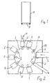
- the packaging machine comprises a container-forming unit, where the vertical portion of the can-shaped container presented in Figure 1 , i.e. casing O having a closed shape, is formed, after which the end member P closing the open end of the casing O is joined to the casing O.
- This can-shaped container one end of which is still open, is transferred to the filling unit of the packaging machine where the final sales package is formed, and which is not described here in greater detail.
- FIG. 2 there is a horizontally rotating transfer table 1, on the perimeter of which there are shaping tools at fixed angular distances, said shaping tools supporting the afore-mentioned container at different forming stages.
- the shaping tools are identical and each consisting of a vertical mandrel 2, around which the casing is formed, said mandrel being later referred to as the wrapping mandrel.
- the container-forming unit comprises a fixed frame, on which the transfer table is arranged so as to rotate, said frame being generally designated by the reference number 10.
- the frame comprises processing stations, equalling the number of wrapping mandrels 2, and a certain forming stage of a can open at one end is carried out at each station.
- the mandrels are positioned at the processing stations and during the transfer stage said mandrels are transferred by a short rotational movement of the table equalling in length the distance between the wrapping mandrels 2, to the following station for next processing stage.
- the processing stations are now described in greater detail mainly on the basis of their function in forming a can-like casing.
- the moving parts are positioned on the frame, mainly on the outside of the circular track of the wrapping mandrels and/or above the mandrels, or said moving parts are arranged in such a way that they are temporarily on the track of the mandrels and move out of the way for the mandrels for the duration of the transfer stage.
- a sidewall blank of a certain height is cut off from the lower end of the blank web, said blank web being transferred to the station with the help of transfer devices positioned on the frame, after which the sidewall blank is pushed onto the wrapping mandrel 2 and wrapped around it into a shape determined by the outer surface of the mandrel.
- the overlapping sidewall edges of the sidewall blank are permanently sealed together. This is performed with the help of a clamping surface, which presses the overlapping edges together and at the same time causes the cooling of the heat seal coating on the inner surface of the sidewall blank, said coating having been previously heated to a bonding temperature.
- the end members whose outlines correspond in shape to the horizontal section of the casing, are separated by die cutting from a continuous blank web M fed into the station, after which said end member is forced through a hole, causing the outer edges of the end member to bend.
- the end member is pushed down onto the open upper end of the casing by using the top surface of the wrapping mandrel as a countersurface in such a way that the upward folded outer edges of the end member are pressed against the inner surface of the casing.
- the same process is carried out in order to ensure sufficient heating around the entire perimeter of the upper end.
- the upper edge of the casing that is above the upward folded ege of the end member is turned by pressing it from above towards the centre and down, whereby the upper edge of the casing is folded over the upward folded outer edge of the end member.
- the edge portion of the casing is pressed against the upward folded edge of the end member, whereby the previously heated heat-seal coatings bond the members together, and the upward folded outer edge of the end member remains permanently sealed inside the U-folded upper edge.
- the same operational stages are performed at different points than in the previous station so that the seal will be even around the entire perimeter of the already finished can-like casing.
- the can-like casing is lifted off the wrapping mandrel 2 and transferred along the conveyor track to the filling unit of the packaging machine.
- a typical processing time at each of the stations A - J is about 500 ms including the transfer from one station to another. Consequently, the can is finished in the container-forming unit in about five seconds, and the production capacity is one can per 0.5 seconds, i.e. about 120 cans per minute.
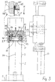
- FIG. 3 presents a container-forming apparatus according to the invention.
- Said apparatus comprises a wrapping mandrel 2, which is used for forming a container, said mandrel being transferred between different processing stations in the afore-described manner.
- the surface of the mandrel supports the casing O, which is wrapped around the mandrel to conform to the shape of said mandrel, and the end of the mandrel, being perpendicular to the casing, supports the end member P at the top, which end member is partly positioned inside the casing, the edges of said end member being folded outwards in an axial direction to the casing O towards the outer edge of said casing.
- Figure 3 presents a situation in which the outer edge of the casing is folded into a U-shape in such a way that the folded edge of the end member P remains inside the end fold, i.e. a can shaped like the one presented in Figure 1 is formed during this stage.
- the container-forming apparatus comprises an end sealing station H, which has a clamping means that moves back and forth in an axial direction to the wrapping mandrel 2.
- the mandrels 2 are positioned on a supporting base plate in an upright position, such as on the afore-described transfer table 1, and the clamping means is arranged with the help of an actuator to move upwards to a position where said clamping means does not prevent the movement of the mandrels down and to operational position in such a way that the clamping means comes into contact with the end member of the can supported by the mandrel.
- the motions have to be rapid, as the processing time at different stations is less than one second.
- the clamping means incorporates a piston H1, which is arranged to move by its own actuator in a longitudinal direction to the casing, i.e. in axial direction to the mandrel.
- a piston H1 On the front portion of the piston, i.e. at the end closest to the mandrel, there is a pushing surface H2 approaching in the outward pushing direction of the piston to the sliding axle HA (central axle of the piston) and the longitudinal axis of the mandrel joining it, said pushing surface H2 being in contact with the radially outermost countersurface H6, and likewise approaching the central axle in clamping member H5.
- Said clamping member H5 is arranged to pivot around a transverse axle H4 against the pushing direction, whereby the outermost surface of the axle H4, seen in radial direction, forms a clamping surface H12.
- the clamping member H5 is turned outwards in the pushing direction in the area in front of the axle H4, whereby in this area the clamping surface at the end of the clamping member is moved towards the opposing, fixed clamping countersurface H11 positioned on the frame of the clamping means.
- clamping member H5 and the frame of the clamping means H3 form clamping jaws, and the above-described end fold of the casing O together with the folded edge of the end member P remaining inside this fold are pressed between these clamping jaws, more accurately between clamping surface H12 and the clamping countersurface H13 1 (see footnote).
- the clamping means incorporates several clamping members H5 arranged radially around the sliding axle HA, each of said clamping members having a similar structure and functioning in the same manner as that described above. All of the clamping members are therefore moved by the same piston H1, the pushing surfaces H2 of said piston forming the front portion of the piston, said front portion tapering into a V- or cone-shape in the pushing direction.
- the clamping members H5 form an opening narrowing in a similar fashion in the pushing direction around the front portion of the piston, into which the front portion of said piston H1 fits.
- Figure 3 further shows how the axles H4 of clamping members H5 are positioned in the pushing direction before the pushing surface H2 and the corresponding countersurface H6.
- the frontmost ends of the clamping members H5 are rapidly turned outwards by the force of the centrally located piston H1, i.e. said ends move rapidly to the operational position, after which the clamping force increases as the piston is pushed forward.
- the axes H4 are formed of the corresponding cylindrical midlines of the axle arms.
- Said axle arms are positioned between the clamping members H5 and the frame H3 of the clamping means in such a way that on the outer surface of the clamping member H5 and on the inner surface of the frame H3 there is a groove curving perpendicular to the axle, which grooves together form a space into which the axle arm fits.
- the clamping countersurfaces H11 on the frame H3 are arranged around the inner surface surrounding the clamping members opposite to the corresponding clamping surfaces H12 of the clamping members H5.
- This inner surface is naturally formed to corresponding in shape to the end of the casing, i.e. in the case of cylindrical containers it is circular.
- the clamping surfaces are correspondingly circular in cross-section perpendicular to the pushing direction.
- Figure 4 which also indicates that there are four of the clamping members H5, i.e. the clamping directions are at angles of 90(, but there may be another sufficient number of the clamping members H5.
- the frame of the clamping means, the clamping members and the piston are most preferably manufactured of some metal suitable for the purpose, including alloys.
- Figure 3 further shows that the piston H1 incprorates a rear portion, said rear portion tapering into a V-shape in the direction opposite to the pushing direction - i.e. in the pulling direction - and being formed by pulling surfaces H7 approaching the sliding axle in this direction. These pulling surfaces are in contact with the countersurfaces H8 of the clamping members, said countersurfaces correspondingly approaching the sliding axle.
- the clamping surfaces H12 of the clamping members H5 can be moved away from the equivalent countersurfaces H11, i.e. the clamping jaws are opened by pulling the piston H1 backwards, whereby the end of the casing can be released from clamping and the clamping means can be moved away from the mandrel when the clamping stage is over. This is also the position of clamping members when the clamping means is again moved to the operational position into contact with the end of the casing and the end member.
- the cycle of operations performed at the work station includes the following successive stages:
- FIG. 5 presents a clamping means in accordance with another embodiment, the main principle of which is otherwise the same except that a balancing ring H9 is placed between the clamping members H5 and the frame H3.
- This balancing ring H9 can be placed in an annular space formed at the back of the clamping surfaces and the countersurfaces as seen from the pushing direction, said annular space being formed behind the shoulders, which are positioned in the inwardly radial direction in relation to of the clamping surface H12 and in the outwardly radial direction in relation to the clamping countersurface H11.
- Figure 5 presents an alternative structure to the above-mentioned separate ring, in which the balancing ring 9 continues as a clamping countersurface H11 fixed to the frame, in the direction of the outermost end of the clamping means, i.e. the balancing ring 9 and the clamping countersurface H11 are located in the same annular member, which is attached to the widening at the end of the frame H3.
- the balancing ring H9 When moving the clamping means to the operational position, the balancing ring H9 meets the upper edge of the casing, i.e. the uppermost point of the U-fold, and makes an even fold.
- the ring also functions as a limiter to the clamping motion.
- the balancing ring H9 can be made of a hard plastic material, avoiding the noise caused by moving metal parts, or of metal.
- Figure 5 further shows a damper ring H10, which is positioned at the end of the clamping members H5, said ring remaining between the clamping members and the frame of the clamping means when the piston is pulled backwards.
- This ring functions as a limiter to the opening of the clamping members and is of certain suitable material, such as a hard plastic.
- Figure 6 presents a situation in which the clamping jaws, formed by the clamping members H5 and the frame H3, are opened. From this figure and the structures described above it is also evident that a short motion is alone sufficient to open the jaws and, correspondingly, to close them.
- the clamping surfaces H12 and the clamping countersurfaces H11 are at a relatively small opening angle, between 4° and 6°, for example about 5° with respect to one another.
- the parts are dimensioned in such a way with respect to one another that when the piston is in its frontmost position, i.e. at maximum clamping, the afore-mentioned surfaces are at least parallel or form an opening angle against the pushing direction.
- Figure 8 presents in more detail the section of the clamping surfaces perpendicular to the sliding axle HA. Both surfaces H11 and H12 are axially grooved in order to get a better grip, whereby the corresponding axial surfaces of the fold of the end member are slightly crimped.
- FIG. 2 there can be two end sealing stations with in principle the same kind of clamping means.
- clamping members can not clamp evenly around the entire circumference of the end seal, it is preferable to arrange the clamping members in the next end sealing station in such a way that they cover the gaps in the preceding end members on this circumference.
- the container-forming unit comprises two successive heating stations E and F, said heating stations being positioned after the pre-heating station C and the end member station D, and as the temperature of the blown air is usually at least 300(C), the heat seal coatings on the surfaces of the end member P and the casing O, said portions placed against each other, are sufficiently hot, and so the clamping surfaces of the clamping means at the end sealing stations H and I do not need to be heated, as the mechanical clamping caused by the clamping surfaces is sufficient to bring about a strong end seal.
- the clamping means is of light and simple structure.
Landscapes
- Engineering & Computer Science (AREA)
- Mechanical Engineering (AREA)
- Chemical & Material Sciences (AREA)
- Combustion & Propulsion (AREA)
- Composite Materials (AREA)
- Making Paper Articles (AREA)
- Closing Of Containers (AREA)
- Control And Other Processes For Unpacking Of Materials (AREA)
- Piezo-Electric Or Mechanical Vibrators, Or Delay Or Filter Circuits (AREA)
- Oscillators With Electromechanical Resonators (AREA)
- Input Circuits Of Receivers And Coupling Of Receivers And Audio Equipment (AREA)
Applications Claiming Priority (3)
| Application Number | Priority Date | Filing Date | Title |
|---|---|---|---|
| FI981222A FI120485B (fi) | 1998-05-29 | 1998-05-29 | Pakkauksenmuodostuslaite |
| FI981222 | 1998-05-29 | ||
| PCT/FI1999/000403 WO1999064227A1 (en) | 1998-05-29 | 1999-05-12 | Apparatus that clamps an end member to a casing |
Publications (2)
| Publication Number | Publication Date |
|---|---|
| EP1091846A1 EP1091846A1 (en) | 2001-04-18 |
| EP1091846B1 true EP1091846B1 (en) | 2008-03-05 |
Family
ID=8551858
Family Applications (1)
| Application Number | Title | Priority Date | Filing Date |
|---|---|---|---|
| EP99923632A Expired - Lifetime EP1091846B1 (en) | 1998-05-29 | 1999-05-12 | Apparatus that clamps an end member to a casing |
Country Status (8)
| Country | Link |
|---|---|
| US (1) | US6558305B1 (enExample) |
| EP (1) | EP1091846B1 (enExample) |
| JP (1) | JP4564168B2 (enExample) |
| AT (1) | ATE388013T1 (enExample) |
| DE (1) | DE69938301T2 (enExample) |
| ES (1) | ES2301240T3 (enExample) |
| FI (1) | FI120485B (enExample) |
| WO (1) | WO1999064227A1 (enExample) |
Cited By (1)
| Publication number | Priority date | Publication date | Assignee | Title |
|---|---|---|---|---|
| CN110650891A (zh) * | 2017-05-23 | 2020-01-03 | A和R卡顿隆德有限公司 | 用于容器元件的定位单元和附接单元 |
Families Citing this family (13)
| Publication number | Priority date | Publication date | Assignee | Title |
|---|---|---|---|---|
| DE10257145A1 (de) | 2002-12-06 | 2004-06-24 | Huhtamaki Ronsberg, Zweigniederlassung Der Huhtamaki Deutschland Gmbh & Co. Kg | Schlauchförmiger, insbesondere dosenförmiger, Behälter zur Aufnahme von Fluiden, Verfahren zu dessen Herstellung und Verwendung |
| US7364047B2 (en) | 2004-05-27 | 2008-04-29 | Zweigniederlassung Der Huhtamaki Deutschaland, Gmbh & Co. Kg | Tubular, especially can-shaped, receptacle for the accommodation of fluids, a method of manufacture, and use |
| USD582790S1 (en) | 2005-04-19 | 2008-12-16 | Huhtamaki Ronsberg, Zweigniederlassung Der Huhtamaki Deutschland Gmbh & Co. Kg | Foil package |
| GB0525979D0 (en) * | 2005-12-21 | 2006-02-01 | Elopak Systems | Improvements in or relating to packaging |
| US7686753B2 (en) * | 2006-07-27 | 2010-03-30 | Paper Machinery Corporation | Bottom finishing station components for a cup making machine |
| US8336186B2 (en) | 2008-01-08 | 2012-12-25 | Packaging Technologies, Inc. | Apparatus for placing and attaching formed filters into brewing cups |
| US9850021B2 (en) | 2011-03-25 | 2017-12-26 | Sonoco Development, Inc. | Paper-based composite container for off-gassing products, and method for making same |
| ES2676279T3 (es) * | 2011-10-06 | 2018-07-18 | Combocap, Inc. | Cápsula |
| US20150099615A1 (en) * | 2013-10-04 | 2015-04-09 | Berry Plastics Corporation | Container-forming process and machine |
| DE102013111230B4 (de) | 2013-10-11 | 2016-01-28 | Sig Technology Ag | Vorrichtung und Verfahren zum flüssigkeitsdichten Versiegeln von zwei sich teilweise überlappenden Verpackungsteilen |
| US11225355B2 (en) | 2017-11-08 | 2022-01-18 | Sonoco Development, Inc. | Membrane lid with integrated peelable portion |
| SE543911C2 (en) * | 2020-01-14 | 2021-09-21 | A & R Carton Lund Ab | An expansible press plunger, an attachment unit for attaching a container element in a container body and a method for attaching a container element in a container body |
| KR20230017267A (ko) | 2020-05-28 | 2023-02-03 | 소노코 디벨럽먼트, 인코포레이티드 | 복합재 용기에 대한 종이 기반 단부 마개의 고속 적용을 위한 시스템 및 방법 |
Family Cites Families (52)
| Publication number | Priority date | Publication date | Assignee | Title |
|---|---|---|---|---|
| DE413236C (de) * | 1925-05-04 | Angelo Piccaluga | Werkzeug zur Herstellung von Kapselverschluessen bei Metallgefaessen | |
| GB374301A (en) * | 1931-02-20 | 1932-06-09 | Continental Can Co | Improvements in or relating to machines for clinching covers to cans |
| US2912282A (en) | 1957-05-16 | 1959-11-10 | Solo Cup Co | Blow off conveyor device for paper cups or the like |
| US3049979A (en) | 1960-12-12 | 1962-08-21 | Frank M Sayford Company | Cup forming method and apparatus |
| US3468226A (en) | 1967-03-08 | 1969-09-23 | Wilbur B England | Cup-making method and apparatus |
| US3579958A (en) | 1969-08-15 | 1971-05-25 | Haskon Inc | Machine for forming, filling, and sealing containers |
| US3589094A (en) | 1970-02-02 | 1971-06-29 | Pearson Co R A | Carton-loading apparatus and method |
| US3668824A (en) * | 1970-11-24 | 1972-06-13 | Nikolai Nikolaevich Solomonov | Device for securing a valve in the neck of an aerosol vessel |
| GB1373088A (en) | 1971-12-31 | 1974-11-06 | Mars Ltd | Beverage-dispensing machines |
| US3764425A (en) | 1972-01-10 | 1973-10-09 | Milprint Inc | Apparatus and method for the manufacture of tubular containers |
| US3964237A (en) | 1972-05-10 | 1976-06-22 | Portion Packaging Limited | Apparatus for the production of a product filled container |
| US3962844A (en) | 1974-08-21 | 1976-06-15 | International Paper Company | Process for forming and applying a hermetic, heat sealed closure |
| US3918236A (en) | 1974-11-04 | 1975-11-11 | Ex Cell O Corp | Method of and machine for forming, filling and closing containers |
| FR2383834A2 (fr) | 1977-03-15 | 1978-10-13 | Gatrun Anstalt | Procede de fabrication et de remplissage a un recipient, tel que gobelet ou bouteille, en matiere plastique |
| US4135347A (en) | 1976-10-15 | 1979-01-23 | International Paper Co. | Method and apparatus for producing a dispensing tube |
| US4100842A (en) | 1977-05-18 | 1978-07-18 | Phillips Petroleum Company | Apparatus for forming a container |
| US4127059A (en) * | 1977-06-06 | 1978-11-28 | Phillips Petroleum Company | Method of forming a container |
| US4317323A (en) | 1977-11-21 | 1982-03-02 | Phillips Petroleum Company | Apparatus for producing containers |
| JPS5833813B2 (ja) | 1977-12-19 | 1983-07-22 | 東洋ガラス株式会社 | プラスチツクスリ−ブの製造方法および装置 |
| DE2844374A1 (de) | 1978-10-11 | 1980-04-17 | Ragnar Svensson | Verfahren und vorrichtung zum verschliessen von an ihrer oberseite offenen gefaessen |
| DE2917304C2 (de) | 1979-04-28 | 1984-05-10 | Maschinenfabrik Rissen Gmbh, 2000 Hamburg | Vorrichtung zum Wickeln einer Hülse |
| US4285750A (en) | 1979-07-23 | 1981-08-25 | Owens-Illinois, Inc. | Method for producing a plastic sleeve |
| DE3015112C2 (de) | 1980-04-19 | 1984-09-06 | 4 P Nicolaus Kempten GmbH, 8960 Kempten | Vorrichtung zum Herstellen eines flüssigkeitsdichten Behälters |
| US4559765A (en) | 1980-07-17 | 1985-12-24 | Maryland Cup Corporation | Apparatus for manufacturing foam plastic containers by use of a tubular forming mandrel |
| GB2103538A (en) * | 1981-06-18 | 1983-02-23 | Unilever Plc | Making drums for packaging |
| US4490130A (en) | 1981-08-10 | 1984-12-25 | Paper Machinery Corporation | Machine for forming seams of two-piece paper cups |
| SE451252B (sv) | 1981-09-08 | 1987-09-21 | Akerlund & Rausing Licens Ab | Forfarande och anordning for framstellning av forpackning med invendig endforslutning |
| US4409045A (en) * | 1982-07-20 | 1983-10-11 | Maryland Cup Corporation | Method and apparatus for sealing the sidewall and bottom seam portions of two-piece containers during manufacture thereof |
| US4581003A (en) | 1983-07-08 | 1986-04-08 | Toppan Printing Co., Ltd. | Method for manufacturing an angled and cylindrical container |
| IT1212928B (it) | 1983-07-12 | 1989-12-07 | Ica Spa | Macchina per il confezionamento integrale di sacchetti partendo da bobine |
| NL8401835A (nl) | 1984-06-08 | 1986-01-02 | Thomassen & Drijver | Werkwijze en inrichting voor het vervaardigen van een van een vulling voorzien blik, een werkwijze voor het vervaardigen van dit blik, en een volgens een werkwijze vervaardigd blik, blikdeel en/of eindwand. |
| US4544431A (en) | 1985-02-06 | 1985-10-01 | Stackpole Limited | Roll fed labelling machine |
| JPS61249739A (ja) | 1985-04-30 | 1986-11-06 | Toyo Glass Kk | プラスチツクスリ−ブの製造方法および装置 |
| CH669130A5 (de) | 1985-06-11 | 1989-02-28 | Elpatronic Ag | Verfahren und vorrichtung zum runden von blechen, insbesondere fuer dosenkoerper. |
| FI854818A0 (fi) | 1985-12-04 | 1985-12-04 | Yhtyneet Paperitehtaat Oy | Foerfarande foer framstaellning av en foerpackning. |
| US4680016A (en) | 1986-01-31 | 1987-07-14 | Lynch Bobby R | Apparatus and method for rimming containers |
| DD254919A1 (de) | 1986-12-18 | 1988-03-16 | Nagema Veb K | Vorrichtung zum herstellen von bodenbeuteln |
| JP2711467B2 (ja) * | 1989-01-26 | 1998-02-10 | 島田理化工業株式会社 | 筒状容器の高周波溶着装置 |
| US5026338A (en) * | 1989-04-14 | 1991-06-25 | Owens-Illinois Plastic Products Inc. | Method for forming a rolled rim in a fabricated thermoplastic container |
| SE466196B (sv) | 1989-06-13 | 1992-01-13 | Pavel Voracek | Foerfarande och anordning foer elektrisk behandling av en elektrolytisk loesning samt loesningsfraktioner framstaellda enligt foerfarandet |
| DE3927199A1 (de) | 1989-08-17 | 1991-02-21 | Tetra Pak Gmbh | Vorrichtung zur herstellung einer fliessmittelpackung |
| JP2813820B2 (ja) | 1989-09-13 | 1998-10-22 | 四国化工機株式会社 | 容器成形装置 |
| US5035106A (en) * | 1989-12-12 | 1991-07-30 | Ccl Industries | Method of sealing a valve to an aerosol container |
| SE9000410L (sv) | 1990-02-06 | 1991-08-07 | Duma Ab | Behaallareanordning och foerfarande foer framstaellning daerav |
| DE4014774A1 (de) | 1990-05-09 | 1991-11-14 | Hoerauf Michael Maschf | Vorrichtung zur herstellung einer dose aus kunststoffbeschichtetem karton |
| SE9102511D0 (sv) | 1991-09-03 | 1991-09-03 | Norden Pac Dev Ab | Method and apparatus for manufacturing a containerfilled with a product |
| US5324249A (en) | 1992-08-28 | 1994-06-28 | Paper Machinery Corporation | Cup making machine |
| DE4417939A1 (de) * | 1994-05-21 | 1995-11-23 | Hoerauf Michael Maschf | Maschine zum Herstellen von Behältern |
| ATE174859T1 (de) * | 1995-04-02 | 1999-01-15 | Werner Grabher | Verfahren und vorrichtung zur herstellung einer dose mit einer verschlussmembran aus folie, sowie halbfertigdose mit membranfolienverschluss |
| US5913798A (en) | 1995-04-02 | 1999-06-22 | Grabher; Werner | Can and closure diaphragm, as well as process and apparatus for tightly connecting a can wall with the closure diaphragm |
| US5752907A (en) | 1995-08-15 | 1998-05-19 | Paper Machinery Corporation | Cup making machine |
| US5785801A (en) | 1996-05-08 | 1998-07-28 | Technimark, Inc. | Apparatus for covering a textile dye tube |
-
1998
- 1998-05-29 FI FI981222A patent/FI120485B/fi not_active IP Right Cessation
-
1999
- 1999-05-12 AT AT99923632T patent/ATE388013T1/de active
- 1999-05-12 WO PCT/FI1999/000403 patent/WO1999064227A1/en not_active Ceased
- 1999-05-12 DE DE69938301T patent/DE69938301T2/de not_active Expired - Lifetime
- 1999-05-12 EP EP99923632A patent/EP1091846B1/en not_active Expired - Lifetime
- 1999-05-12 ES ES99923632T patent/ES2301240T3/es not_active Expired - Lifetime
- 1999-05-12 JP JP2000553267A patent/JP4564168B2/ja not_active Expired - Fee Related
-
2000
- 2000-11-20 US US09/716,638 patent/US6558305B1/en not_active Expired - Lifetime
Cited By (2)
| Publication number | Priority date | Publication date | Assignee | Title |
|---|---|---|---|---|
| CN110650891A (zh) * | 2017-05-23 | 2020-01-03 | A和R卡顿隆德有限公司 | 用于容器元件的定位单元和附接单元 |
| US11292625B2 (en) | 2017-05-23 | 2022-04-05 | Ar Packaging Systems Ab | Positioning unit and attachment unit for container element |
Also Published As
| Publication number | Publication date |
|---|---|
| FI981222A0 (fi) | 1998-05-29 |
| FI120485B (fi) | 2009-11-13 |
| FI981222L (fi) | 1999-11-30 |
| DE69938301T2 (de) | 2009-02-26 |
| JP2002517336A (ja) | 2002-06-18 |
| ATE388013T1 (de) | 2008-03-15 |
| JP4564168B2 (ja) | 2010-10-20 |
| ES2301240T3 (es) | 2008-06-16 |
| WO1999064227A1 (en) | 1999-12-16 |
| US6558305B1 (en) | 2003-05-06 |
| DE69938301D1 (de) | 2008-04-17 |
| EP1091846A1 (en) | 2001-04-18 |
Similar Documents
| Publication | Publication Date | Title |
|---|---|---|
| EP1091846B1 (en) | Apparatus that clamps an end member to a casing | |
| US9321557B2 (en) | Method and apparatus for producing labeled, plastic foam containers, and product of same | |
| US4034537A (en) | Method and apparatus for the continuous manufacture of packages for liquids | |
| EP2049326B1 (en) | Bottom finishing station components for a cup making machine | |
| US5964687A (en) | Container fitment applicator | |
| US6722104B1 (en) | Method and packaging machine for forming a container, a blank web and a filled container | |
| US5752907A (en) | Cup making machine | |
| US4528803A (en) | Machine for the fabrication, filling, and sealing of packages | |
| CN116056978A (zh) | 用于复合容器上的纸基端部封闭件的高速应用的系统及方法 | |
| JPH0317710B2 (enExample) | ||
| CA1059360A (en) | Container manufacture | |
| WO2010049589A1 (en) | Device for pressing and seaming | |
| AU2001285355A1 (en) | Method and apparatus for constructing an end portion of a food sauce dispensing cartridge | |
| WO2002045944A1 (en) | Method and apparatus for constructing an end portion of a food sauce dispensing cartridge | |
| US12343955B2 (en) | Machine for manufacturing disposable cups | |
| US3799820A (en) | Process of manufacturing open or closed packagings of foam plastics,preferably foam polystyrene | |
| JPH0375249B2 (enExample) | ||
| US3896710A (en) | Foldable tubular package apparatus | |
| CA1174157A (en) | Machine for manufacturing, filling and sealing packages | |
| RU2785933C2 (ru) | Способ упаковывания порционных, жидких или пастообразных в состоянии обработки продуктов и упаковочная машина для осуществления указанного способа | |
| US3851568A (en) | Foldable tubular package apparatus | |
| JPH0437048Y2 (enExample) | ||
| EP4408652A1 (en) | Machine for manufacturing disposable cups | |
| WO1999065669A1 (en) | A method and device for a packaging machine | |
| JPS60230838A (ja) | 容器形成方法および装置 |
Legal Events
| Date | Code | Title | Description |
|---|---|---|---|
| PUAI | Public reference made under article 153(3) epc to a published international application that has entered the european phase |
Free format text: ORIGINAL CODE: 0009012 |
|
| 17P | Request for examination filed |
Effective date: 20001214 |
|
| AK | Designated contracting states |
Kind code of ref document: A1 Designated state(s): AT DE ES FR GB IT NL SE |
|
| 17Q | First examination report despatched |
Effective date: 20030530 |
|
| RAP1 | Party data changed (applicant data changed or rights of an application transferred) |
Owner name: LAMICAN OY |
|
| GRAP | Despatch of communication of intention to grant a patent |
Free format text: ORIGINAL CODE: EPIDOSNIGR1 |
|
| RIC1 | Information provided on ipc code assigned before grant |
Ipc: B31B 17/30 20060101ALI20070920BHEP Ipc: B31B 1/30 20060101AFI20070920BHEP |
|
| GRAS | Grant fee paid |
Free format text: ORIGINAL CODE: EPIDOSNIGR3 |
|
| GRAA | (expected) grant |
Free format text: ORIGINAL CODE: 0009210 |
|
| AK | Designated contracting states |
Kind code of ref document: B1 Designated state(s): AT DE ES FR GB IT NL SE |
|
| REG | Reference to a national code |
Ref country code: GB Ref legal event code: FG4D |
|
| REF | Corresponds to: |
Ref document number: 69938301 Country of ref document: DE Date of ref document: 20080417 Kind code of ref document: P |
|
| REG | Reference to a national code |
Ref country code: ES Ref legal event code: FG2A Ref document number: 2301240 Country of ref document: ES Kind code of ref document: T3 |
|
| REG | Reference to a national code |
Ref country code: SE Ref legal event code: TRGR |
|
| ET | Fr: translation filed | ||
| REG | Reference to a national code |
Ref country code: GB Ref legal event code: 732E |
|
| RAP2 | Party data changed (patent owner data changed or rights of a patent transferred) |
Owner name: LAMICAN OY |
|
| NLS | Nl: assignments of ep-patents |
Owner name: LAMICAN OY Effective date: 20081014 |
|
| NLT1 | Nl: modifications of names registered in virtue of documents presented to the patent office pursuant to art. 16 a, paragraph 1 |
Owner name: BHM INDUSTRIAL DEVELOPMENT OY |
|
| NLT2 | Nl: modifications (of names), taken from the european patent patent bulletin |
Owner name: LAMICAN OY Effective date: 20081119 |
|
| PLBE | No opposition filed within time limit |
Free format text: ORIGINAL CODE: 0009261 |
|
| STAA | Information on the status of an ep patent application or granted ep patent |
Free format text: STATUS: NO OPPOSITION FILED WITHIN TIME LIMIT |
|
| 26N | No opposition filed |
Effective date: 20081208 |
|
| REG | Reference to a national code |
Ref country code: FR Ref legal event code: TP Ref country code: FR Ref legal event code: CD |
|
| REG | Reference to a national code |
Ref country code: FR Ref legal event code: PLFP Year of fee payment: 17 |
|
| PGFP | Annual fee paid to national office [announced via postgrant information from national office to epo] |
Ref country code: SE Payment date: 20150522 Year of fee payment: 17 Ref country code: GB Payment date: 20150526 Year of fee payment: 17 Ref country code: DE Payment date: 20150525 Year of fee payment: 17 Ref country code: ES Payment date: 20150512 Year of fee payment: 17 |
|
| PGFP | Annual fee paid to national office [announced via postgrant information from national office to epo] |
Ref country code: NL Payment date: 20150519 Year of fee payment: 17 Ref country code: FR Payment date: 20150601 Year of fee payment: 17 Ref country code: IT Payment date: 20150513 Year of fee payment: 17 Ref country code: AT Payment date: 20150512 Year of fee payment: 17 |
|
| REG | Reference to a national code |
Ref country code: DE Ref legal event code: R079 Ref document number: 69938301 Country of ref document: DE Free format text: PREVIOUS MAIN CLASS: B31B0001300000 Ipc: B31B0050300000 |
|
| REG | Reference to a national code |
Ref country code: DE Ref legal event code: R119 Ref document number: 69938301 Country of ref document: DE |
|
| REG | Reference to a national code |
Ref country code: NL Ref legal event code: MM Effective date: 20160601 |
|
| REG | Reference to a national code |
Ref country code: AT Ref legal event code: MM01 Ref document number: 388013 Country of ref document: AT Kind code of ref document: T Effective date: 20160512 |
|
| GBPC | Gb: european patent ceased through non-payment of renewal fee |
Effective date: 20160512 |
|
| PG25 | Lapsed in a contracting state [announced via postgrant information from national office to epo] |
Ref country code: SE Free format text: LAPSE BECAUSE OF NON-PAYMENT OF DUE FEES Effective date: 20160513 Ref country code: AT Free format text: LAPSE BECAUSE OF NON-PAYMENT OF DUE FEES Effective date: 20160512 Ref country code: NL Free format text: LAPSE BECAUSE OF NON-PAYMENT OF DUE FEES Effective date: 20160601 Ref country code: IT Free format text: LAPSE BECAUSE OF NON-PAYMENT OF DUE FEES Effective date: 20160512 |
|
| REG | Reference to a national code |
Ref country code: FR Ref legal event code: ST Effective date: 20170131 |
|
| PG25 | Lapsed in a contracting state [announced via postgrant information from national office to epo] |
Ref country code: DE Free format text: LAPSE BECAUSE OF NON-PAYMENT OF DUE FEES Effective date: 20161201 Ref country code: FR Free format text: LAPSE BECAUSE OF NON-PAYMENT OF DUE FEES Effective date: 20160531 |
|
| PG25 | Lapsed in a contracting state [announced via postgrant information from national office to epo] |
Ref country code: GB Free format text: LAPSE BECAUSE OF NON-PAYMENT OF DUE FEES Effective date: 20160512 |
|
| PG25 | Lapsed in a contracting state [announced via postgrant information from national office to epo] |
Ref country code: ES Free format text: LAPSE BECAUSE OF NON-PAYMENT OF DUE FEES Effective date: 20160513 |
|
| REG | Reference to a national code |
Ref country code: ES Ref legal event code: FD2A Effective date: 20180625 |