EP1089236A2 - Verfahren zur Darstellung eines dreidimensionalen Objektes durch ein zweidimensionales Bild - Google Patents
Verfahren zur Darstellung eines dreidimensionalen Objektes durch ein zweidimensionales Bild Download PDFInfo
- Publication number
- EP1089236A2 EP1089236A2 EP20000203242 EP00203242A EP1089236A2 EP 1089236 A2 EP1089236 A2 EP 1089236A2 EP 20000203242 EP20000203242 EP 20000203242 EP 00203242 A EP00203242 A EP 00203242A EP 1089236 A2 EP1089236 A2 EP 1089236A2
- Authority
- EP
- European Patent Office
- Prior art keywords
- grid
- points
- image
- image data
- dimensional
- Prior art date
- Legal status (The legal status is an assumption and is not a legal conclusion. Google has not performed a legal analysis and makes no representation as to the accuracy of the status listed.)
- Withdrawn
Links
Images



Classifications
-
- G—PHYSICS
- G06—COMPUTING OR CALCULATING; COUNTING
- G06T—IMAGE DATA PROCESSING OR GENERATION, IN GENERAL
- G06T17/00—Three-dimensional [3D] modelling for computer graphics
Definitions
- the invention relates to a method for representing a at the grid points regular grid through a three-dimensional data set of defined objects a two-dimensional image, the image values at the pixels that make up the composes two-dimensional image, from the image data of the three-dimensional data set are derived, which are each assigned to a beam through the object. Moreover the invention relates to an imaging system for performing this Procedure.
- volume rendering or "ray-tracing” is known. These procedures include the projection (usually a parallel projection or a cone beam projection) of a three-dimensional object on a two-dimensional image.
- projection usually a parallel projection or a cone beam projection
- This image data is summed (weighted if necessary), or selected according to their size, for example the minimum, the median or the maximum.
- a preferred application arises in connection with the images acquired through a C-arm system, in which the object consists of a variety directions are irradiated and from which a three-dimensional data set is reconstructed which then becomes a two-dimensional one with the method mentioned at the beginning Image is generated for a predefinable projection geometry.
- projection image data In order to be able to calculate the image value of a pixel, projection image data must be used be known at the various points on the beam. These points fall in the However, do not usually coincide with the grid points at which the one to be displayed Function - e.g. the absorption of X-rays - is defined.
- the projection image data must therefore be interpolated from the image data of the three-dimensional Data record can be derived.
- the image data are three-dimensional Data set defined at the lattice points of a periodic cubic lattice composed of units with eight grid points each at the corners of a cube. For each point is therefore an interpolation from the image data at the eight grid points of the Cube that encloses the point in question is required.
- Such a trilinear interpolation requires 14 additions and 7 multiplications.
- the object of the present invention is to reduce the effort required to carry out a to reduce such procedure.
- a BCC lattice consists of two identical, cubic sublattices that are against each other are offset so that each lattice point of the one sublattice in the center one Cube from the other sub-grid lies - and vice versa.
- BCC body centered cubic
- the invention is based on the knowledge that the basic form of a BCC grid - eight Lattice points at the corners and one in the middle divided into similar tetrahedra can be that every point with any position in this basic form within a this tetrahedron lies. For these points there is only a (linear) interpolation required between the image data at the corner points of this tetrahedron. The computing effort is significantly reduced - with at least the same image quality.
- the projection image data can be used for the "volume rendering” or "ray tracing” methods are used. However, one only calculates the projection image data for points that lie in a (randomly oriented) flat layer, then can an image of this layer from the three-dimensional data set by interpolation determine.
- the points in the two-dimensional image to be generated are called Pixels "and the values assigned to them as Image values ".
- the dots on a three-dimensional grid are called Grid points "and the values assigned to them as Image data "(single: value).”.
- the points that lie along a beam and are projected onto a pixel are called Points "and the values assigned to them as Projection Image Data "(single: projection value).
- a preferred embodiment of the invention is described in claim 2.
- Another The alternative would be to use a different grid, e.g. a simple cubic Convert grid-reconstructed image data to a BCC grid.
- a different grid e.g. a simple cubic Convert grid-reconstructed image data to a BCC grid.
- additional Computing effort for the conversion would also be this alternative with regard to the Computing effort and image quality are still an advantage.
- Claim 3 describes a preferred field of application of the invention.
- the invention but is also applicable to other modalities, for example ultrasound or Magnetic resonance investigations or in all methods, in which one on one three-dimensional grid scanned function represented as a two-dimensional image shall be.
- Claim 4 describes an imaging system for performing the method according to Claim 1.
- the computing speed at a higher hardware expenditure can be increased.
- the Hardware effort is less than that for processing one at the grid points a cubic lattice required effort, while at the same time on eight Memory should be accessed.
- Claim 6 describes a preferred embodiment of the imaging system, which also could be realized with an x-ray computer tomograph, but will be after the further embodiment according to claim 7 X-ray systems preferably in those X-ray emitter and X-ray image converter on a pivotable about at least one axis C-arms are attached.
- the X-ray system shown in FIG. 1 comprises an X-ray emitter 1 and one Image converter 2 in the form of an X-ray image intensifier, which at the ends of a C-shaped Bow 3 are attached.
- the arch 3 is - around two mutually perpendicular, horizontal Swiveling axes - attached to a tripod 4, which can be moved on the ceiling or on the floor. It is therefore possible to place one on a patient table 5 radiating patients from all possible directions.
- the system 1,2 can be pivoted on a circular arc of at least 180 ° around the patient X-rays are continuously generated.
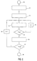
- the measured values that are required for the reconstruction of the absorption within the object are acquired in step 101.
- the X-ray emitter 1 and the image converter 2 are moved around the object, preferably on two arcs inclined relative to one another, at least 180 °, a large number of X-ray images being produced in each case.
- the measured values defined by the brightness values of the x-ray image are digitized and fed to the mentioned image processing device, which in step 102 reconstructs the absorption of the object at the grid points of a periodic three-dimensional grid.
- the reconstruction can take place according to an algorithm known from computer tomography and adapted to the special features of the C-arm system.
- the reconstruction takes place at the grid points of a BCC grid.
- a BCC lattice consists of two identical cubic sublattices, each offset in the x, y and z directions by half the distance between two adjacent points on a sublattice (assuming that the lattice lines are in x-, y- and z direction).
- Each grid point of one subgrid is thus in the center of eight grid points of the other subgrid. This is shown in Fig. 3a for a basic element.
- each of the grid points G 1 Vietnamese G 8 is in the center of a cell of the other sub-grid, of which only a single grid point - g 9 - is shown in FIG. 3a.
- a volume element can be assigned to each individual grid point on these two sub-grids or in the BCC grid, which encloses all the points in space that are closer to this grid point than to all other grid points.
- a voxel is shown in Fig. 3b.
- Its 14 side surfaces are defined by the median plane between the grid point (g 9 ) in the center of this voxel and one of the neighboring grid points.
- the side surfaces between the center point and the eight grid points of the other sub-grid enclosing it are hexagonal, while the side surfaces between the center point (g 9 ) and the six grid points in front of and behind, above and below, left and right of this grid point are square.
- the polyhedron formed in this way is known as the "octahedron”.
- FIG. 4a the basic element of a simple cubic lattice shown, which consists of eight grid points arranged on the corners of a cube are.
- Figure 4b shows a single voxel of such a simple cubic lattice Since each grid point has exactly six closest grid points, there are six square ones in the middle between two neighboring grid points Boundaries that together form a cube.
- the voxels have the same volume.
- 3b has the voxel a better match with the ideal spherical shape than the voxel according to Fig.4b.
- the largest ball that can be inscribed in the voxel according to FIG. 3b has a 12% larger radius than the ball that just barely into the cube-shaped voxel according to Fig. 4b fits.
- the absorption distribution immediately at the lattice points To reconstruct a BCC grid it has to be subsequently calculated for such a grid become.
- a value for an im Additional lattice point located in the center can be determined by means of interpolation, or by the sum of the values reconstructed at the eight grid points divided by 8.
- a two-dimensional image is calculated from the three-dimensional image.
- the geometrical foundations for this are shown in FIG. 5.
- the object O the absorption of which has previously been reconstructed at the grid points of a BCC grid, is projected onto individual pixels of a two-dimensional image I by preferably parallel rays R 1 .... R j .... R n .
- An image value for the image point belonging to the beam in the two-dimensional image I is derived from the projection image data which are assigned to the individual points of a beam within the object - such as point P ij for the beam R j , for example, by adding the sum or the weighted sum of the projection image data is formed, which are assigned to the points on the relevant beam.
- step 103 a projection value is determined for the points P ij on the beam R j - and for all other points on this and all other beams - by an interpolation of image data to be explained at the grid points of the BCC grid.
- an image value for the image point which is assigned to this beam is derived from this in step 106.
- this image value can be determined as a (weighted) sum of the projection image data or as its minimum, maximum, median or any other value.
- the cell of one of the two sub-grids is determined in block 202, which includes the respective point on the beam - such as point P ij .
- the grid point located on the rear, lower, left corner this is shown in FIG. 3a G 8 ) or the address area in which the image data at the grid points of this cell are stored.
- This grid point shown in bold in FIG. 7a, is assigned the origin of a Cartesian coordinate system whose coordinate axes coincide with the grid lines.
- the center point (g 9 , in FIG. 3a) of this cell is determined with the coordinates (1 ⁇ 2, 1 ⁇ 2, 1 ⁇ 2), which is a grid point of the other subgrid (see FIGS. 7a and 7b). The value for this central point affects the projection value of each point within the associated cell.
- the sub-cube is determined which fills 1/8 of the volume of the cell and in which the point P ij is located.
- steps 202 and 203 two grid points (G 8 and g 9 ) have already been determined, which form the corner points of a tetrahedron which includes the sought point P ij .
- the two further corner points of the tetrahedron which are also grid points of the cell shown in FIGS. 7 a ff, are determined in step 204 from three additional grid points which are opposite the grid point G 8 to which the sub-cube is assigned (FIG. 7 c), are offset either in the x or y or in the z direction - in the example these are G 4 , G 7 , and G 5 , cf. Fig. 3a.
- the image data at five grid points are of interest for the calculation of the projection image data at points in a sub-cube.
- FIGS. 7d, 7e and 7f There are three possibilities, which are outlined in FIGS. 7d, 7e and 7f.
- the two remaining grid points are in the x, z plane.
- Fig. 7e the two additional lattice points that define the tetrahedron are in the x, y plane.
- the third possibility is shown in Fig. 7f.
- the two additional grid points lie in the y, z direction.
- One of these tetrahedra - depending on the three coordinates q x , q y , or q z - is used for the interpolation.
- the value f 3 is required for the calculation of the projection image data at all points located in the cell.
- the two image data to be used are determined from the image data f x , f y and f z as a function of the coordinates q x , q y and q z of the point P ij as follows:
- an absorption value for the point Pij is calculated in step 205 by a simple linear interpolation.
- b ij is the projection value calculated for point P ij
- step 204 This interpolation therefore only requires 8 additions and 3 multiplications - if one neglects the multiplication by 2 because it is just a simple shift operation require a place to the left.
- 3 comparisons equivalent to 3 additions
- step 204 is a total of 11 additions and 3 Multiplications required, which is significantly less than the 14 additions and 7 Multiplications that were required with a simple cubic grid.
- the interpolation step is ended (block 206).
- a significant acceleration of the linear interpolation in step 205 can be achieved if the absorption values or image data are stored in five memories that can be read out simultaneously.
- the absorption values or image data for the five grid points from which the three possible tetrahedra are formed must always be distributed to all five memories, because they can then be read out from the memories at the same time. This is the case, for example, when only one of the cell diagonally opposed grid points (e.g. G 8 and G 2 in Fig. 3A) stores absorption values in the same memory and when the absorption values for the grid points (e.g. g 9 ) of the other Subgitters are stored separately in one of the five memories.
- each tetrahedron is defined by 3 grid points of one sub-grid and the associated center (g 9 ) of the other sub-grid.
- each point P ij is always in a cell of the other sub-lattice, it is also possible to use a tetrahedron from which three vertices are defined by the lattice points of the other sub-lattice and one lattice point of the one sub-lattice. You can also use both options and assign a value to the point P ij that corresponds to the mean value that results from the two calculations.
Landscapes
- Physics & Mathematics (AREA)
- Engineering & Computer Science (AREA)
- Computer Graphics (AREA)
- Geometry (AREA)
- Software Systems (AREA)
- General Physics & Mathematics (AREA)
- Theoretical Computer Science (AREA)
- Image Processing (AREA)
- Apparatus For Radiation Diagnosis (AREA)
- Image Analysis (AREA)
- Image Generation (AREA)
Abstract
Description

- Fig. 1
- ein Röntgensystem bei dem die Erfindung anwendbar ist,
- Fig. 2
- ein Ablaufdiagramm des erfindungsgemäßen Verfahrens,
- Fig. 3a und 3b
- die Grundelemente eines BCC-Gitters,
- Fig. 4a und 4b
- Grundelemente eines einfachen kubischen Gitters,
- Fig. 5
- die geometrischen Verhältnisse bei der Ableitung eines 2D-Bildes aus einem 3D-Datensatz,
- Fig. 6
- ein Ablaufdiagramm für den Interpolationsschritt bei Fig. 2,
- Fig. 7a bis 7f
- die dazu gehörenden geometrischen Verhältnisse und
Die Rekonstruktion erfolgt an den Gitterpunkten eines BCC-Gitters. Ein BCC-Gitter besteht aus zwei identischen kubischen Subgittern, die in x-,y- und z-Richtung jeweils um den halben Abstand zweier benachbarter Punkte auf einem Subgitter gegeneinander versetzt sind (wobei angenommen ist, dass die Gitterlinien in x-,y- und z-Richtung verlaufen). Somit befindet sich jeder Gitterpunkt des einen Subgitters im Zentrum von acht Gitterpunkten des jeweils anderen Subgitters. Dies ist in Fig. 3a für ein Grundelement dargestellt. Man erkennt die acht Gitterpunkte G1.....G8 eines regelmäßigen kubischen Subgitters, in deren Mitte sich ein Gitterpunkt g9 des anderen Subgitters befindet. Umgekehrt befindet sich jeder der Gitterpunkte G1.....G8 im Zentrum je einer Zelle des anderen Subgitters, von dem in Fig. 3a lediglich ein einziger Gitterpunkt - g9-dargestellt ist.
Claims (7)
- Verfahren zur Darstellung eines an den Gitterpunkten eines regelmäßigen Gitters durch einen dreidimensionalen Datensatz definierten Objektes durch ein zweidimensionales Bild, wobei die Bildwerte an den Bildpunkten, aus denen sich das zweidimensionale Bild zusammensetzt, aus den Bilddaten des dreidimensionalen Datensatzes abgeleitet werden, die je einem Strahl durch das Objekt zugeordnet sind,
gekennzeichnet durch folgende Schritte:a) Ermittlung der Bilddaten des dreidimensionalen Datensatzes an den Gitterpunkten eines BCC-Gitters,b) Berechnung von Projektions-Bilddaten an Punkten auf den Strahlen durch Interpolation der Bilddaten an vier Gitterpunkten des BCC-Gitters, die die Eckpunkte eines Tetraeders bilden, das je einen der Punkte umschließt,c) Ableitung je eines Bildwertes aus den je einem der Strahlen zugeordneten Projektions-Bilddaten. - Verfahren nach Anspruch 1 für die bildgebende medizinische Diagnostik gekennzeichnet durch die Schritte:a) Akquisition von Meßwerten, die einen physikalischen Parameter des Objektes definieren,b) Rekonstruktion der Parameter an den Gitterpunkten eines BCC-Gitters zur Erzeugung des dreidimensionalen Datensatzes.
- Verfahren nach Anspruch 2,
dadurch gekennzeichnet,
dass die Meßwerte mittels eines das Objekte aus verschiedenen Richtungen durchstrahlenden Röntgensystems akquiriert werden. - Bildgebendes System für die medizinische Diagnostik zur Durchführung des Verfahrens nach Anspruch 1 mit Mitteln zur Darstellung eines an den Gitterpunkten eines regelmäßigen Gitters durch einen dreidimensionalen Datensatz definierten Objektes durch ein zweidimensionales Bild, wobei die Bildwerte an den Bildpunkten, aus denen sich das zweidimensionale Bild zusammensetzt, aus den Bilddaten des dreidimensionalen Datensatzes abgeleitet werden, die je einem Strahl durch das Objekt zugeordnet sind,
gekennzeichnet durcha) Mittel zur Ermittlung der Bilddaten des dreidimensionalen Datensatzes an den Gitterpunkten eines BCC-Gitters,b) Berechnungsmittel zur Berechnung von Projektions-Bilddaten an Punkten auf den Strahlen durch Interpolation der Bilddaten an vier Gitterpunkten des BCC-Gitters, die die Eckpunkte eines Tetraeders bilden, das je einen der Punkte umschließt,c) Mittel zur Ableitung je eines Bildwertes aus den je einem der Strahlen zugeordneten Projektions-Bilddaten. - Bildgebendes System nach Anspruch 4,
dadurch gekennzeichnet,
dass den Berechnungsmitteln fünf Speicher zugeordnet sind, in denen die Bilddaten so gespeichert sind, dass die für eine Interpolation heranzuziehenden Bilddaten gleichzeitig aus den fünf Speichern auslesbar sind. - Bildgebendes System nach Anspruch 4,
dadurch gekennzeichnet,
dass zur Akquisition von Meßwerten für die Absorption der Röntgenstrahlung durch ein Objekt ein Röntgenstrahler zur Durchstrahlung des Objektes aus einer Vielzahl von Richtungen und ein damit gekoppelter Röntgen-Bildwandler vorgesehen sind. - Bildgebendes System nach Anspruch 6,
dadurch gekennzeichnet,
dass der Röntgenstrahler und der Röntgen-Bildwandler an einem um mindestens eine Achse schwenkbaren C-förmigen Bogen befestigt sind.
Applications Claiming Priority (2)
| Application Number | Priority Date | Filing Date | Title |
|---|---|---|---|
| DE1999145380 DE19945380A1 (de) | 1999-09-22 | 1999-09-22 | Verfahren zur Darstellung eines dreidimensionalen Objektes durch ein zweidimensionales Bild |
| DE19945380 | 1999-09-22 |
Publications (1)
| Publication Number | Publication Date |
|---|---|
| EP1089236A2 true EP1089236A2 (de) | 2001-04-04 |
Family
ID=7922883
Family Applications (1)
| Application Number | Title | Priority Date | Filing Date |
|---|---|---|---|
| EP20000203242 Withdrawn EP1089236A2 (de) | 1999-09-22 | 2000-09-15 | Verfahren zur Darstellung eines dreidimensionalen Objektes durch ein zweidimensionales Bild |
Country Status (3)
| Country | Link |
|---|---|
| EP (1) | EP1089236A2 (de) |
| JP (1) | JP2001134780A (de) |
| DE (1) | DE19945380A1 (de) |
Families Citing this family (3)
| Publication number | Priority date | Publication date | Assignee | Title |
|---|---|---|---|---|
| JP2002152534A (ja) * | 2000-11-14 | 2002-05-24 | Matsushita Electric Ind Co Ltd | 三次元信号変換方法及び装置 |
| JP3986051B2 (ja) | 2002-04-30 | 2007-10-03 | 株式会社半導体エネルギー研究所 | 発光装置、電子機器 |
| DE102004045989B4 (de) * | 2004-09-22 | 2007-04-26 | Siemens Ag | Vorrichtung zum Führen eines magnetischen Elements |
-
1999
- 1999-09-22 DE DE1999145380 patent/DE19945380A1/de not_active Withdrawn
-
2000
- 2000-09-15 EP EP20000203242 patent/EP1089236A2/de not_active Withdrawn
- 2000-09-21 JP JP2000287021A patent/JP2001134780A/ja active Pending
Also Published As
| Publication number | Publication date |
|---|---|
| DE19945380A1 (de) | 2001-03-29 |
| JP2001134780A (ja) | 2001-05-18 |
Similar Documents
| Publication | Publication Date | Title |
|---|---|---|
| DE69128341T2 (de) | Parallel-verarbeitungsverfahren und -vorrichtung zur algebraischen rekonstruktion einer dreidimensionalen computertomographie | |
| DE69631225T2 (de) | Bildrekonstruktion von spiralabgetasteten Teilkegelstrahldaten | |
| DE69233207T2 (de) | Verfahren und gerät zur bildverarbeitung. | |
| DE3789650T2 (de) | Verfahren und System zur Festkörpermodellierung. | |
| DE69708892T2 (de) | Dreidimensionales bildrekonstruktionsverfahren, vorzugsweise eines dreidimensionalen angiographischen bildes | |
| DE60313742T2 (de) | Verfahren und geräte für schnelle fächerstrahl-tomographie | |
| EP0004258B1 (de) | Computer-Tomograph zur Durchstrahlung eines Körpers | |
| DE69816824T2 (de) | Texturabbildung in 3-d-rechnergraphik | |
| DE2804732C2 (de) | Medizinisches Untersuchungsgerät | |
| DE19858306A1 (de) | C-Arm Kalibrierungsverfahren unter Anwendung einer planaren Transformation zur 3D-Rekonstruktion bei einem Bildsystem | |
| DE69218839T2 (de) | Tomographische Bilderzeugung mittels Schrägstrahlen | |
| DE10297272T5 (de) | Vielseitige Strahlenkegel-Bildgebungsvorrichtung und -verfahren | |
| DE69720229T2 (de) | Eine computertomographische methode und ein computertomograph | |
| DE69314231T2 (de) | Belichtungseffekte für ein digitales Videoeffektensystem | |
| DE19545778A1 (de) | Verfahren und Einrichtung zum Maskieren von entweder durch Wendelabtastung eines interessierenden Bereichs oder durch Wendelabtastung erzeugten Kegelstrahl-Projektionsdaten | |
| DE102006041033A1 (de) | Verfahren zur Rekonstruktion eines dreidimensionalen Bildvolumens und Röntgengeräte | |
| DE19945636A1 (de) | Verfahren und Vorrichtung zum dreidimensionalen CT-Abbilden eines interessierenden Bereichs in einem Objekt | |
| DE19723095C2 (de) | Bildrekonstruktionsverfahren für einen Computertomographen | |
| DE602004007930T2 (de) | TOMOGRAPHISCHES FOURIER-BILDREKONSTRUKTIONSVERFAHREN FÜR Fächerstrahl-DATEN | |
| DE102004029635A1 (de) | Digitales Linearspur-Tomosynthesesystem und -verfahren | |
| DE3735519C2 (de) | Binäre Rauminterpolation | |
| DE60036393T2 (de) | Verfahren zur schnellen rückprojektion von bildern durch mehrstufige bereichszerlegung | |
| DE102007039573A1 (de) | Verfahren zur analytischen Rekonstruktion für eine Mehrfachquellen-Inversgeometrie-CT | |
| DE19856026A1 (de) | Verfahren und Vorrichtung zur dreidimensionalen Abbildung mit computerisierter Tomographie | |
| DE102012104599A1 (de) | Verfahren und System zur Rekonstruktion tomografischer Bilder |
Legal Events
| Date | Code | Title | Description |
|---|---|---|---|
| PUAI | Public reference made under article 153(3) epc to a published international application that has entered the european phase |
Free format text: ORIGINAL CODE: 0009012 |
|
| AK | Designated contracting states |
Kind code of ref document: A2 Designated state(s): AT BE CH CY DE DK ES FI FR GB GR IE IT LI LU MC NL PT SE |
|
| AX | Request for extension of the european patent |
Free format text: AL;LT;LV;MK;RO;SI |
|
| RAP1 | Party data changed (applicant data changed or rights of an application transferred) |
Owner name: PHILIPS CORPORATE INTELLECTUAL PROPERTY GMBH Owner name: KONINKLIJKE PHILIPS ELECTRONICS N.V. |
|
| RAP1 | Party data changed (applicant data changed or rights of an application transferred) |
Owner name: KONINKLIJKE PHILIPS ELECTRONICS N.V. Owner name: PHILIPS INTELLECTUAL PROPERTY & STANDARDS GMBH |
|
| STAA | Information on the status of an ep patent application or granted ep patent |
Free format text: STATUS: THE APPLICATION HAS BEEN WITHDRAWN |
|
| 18W | Application withdrawn |
Effective date: 20030613 |