EP1088509A1 - Haushalt-Geschirrspülmaschine - Google Patents
Haushalt-Geschirrspülmaschine Download PDFInfo
- Publication number
- EP1088509A1 EP1088509A1 EP00120950A EP00120950A EP1088509A1 EP 1088509 A1 EP1088509 A1 EP 1088509A1 EP 00120950 A EP00120950 A EP 00120950A EP 00120950 A EP00120950 A EP 00120950A EP 1088509 A1 EP1088509 A1 EP 1088509A1
- Authority
- EP
- European Patent Office
- Prior art keywords
- valve body
- liquid
- household dishwasher
- dishwasher according
- reversing device
- Prior art date
- Legal status (The legal status is an assumption and is not a legal conclusion. Google has not performed a legal analysis and makes no representation as to the accuracy of the status listed.)
- Granted
Links
- 239000007921 spray Substances 0.000 claims abstract description 31
- 239000007788 liquid Substances 0.000 claims description 73
- 235000014676 Phragmites communis Nutrition 0.000 claims description 3
- 230000004888 barrier function Effects 0.000 claims description 3
- XLYOFNOQVPJJNP-UHFFFAOYSA-N water Substances O XLYOFNOQVPJJNP-UHFFFAOYSA-N 0.000 description 7
- 238000001514 detection method Methods 0.000 description 3
- 238000011161 development Methods 0.000 description 3
- 230000018109 developmental process Effects 0.000 description 3
- 230000005484 gravity Effects 0.000 description 3
- 238000005406 washing Methods 0.000 description 3
- 208000012661 Dyskinesia Diseases 0.000 description 2
- 230000017311 musculoskeletal movement, spinal reflex action Effects 0.000 description 2
- 238000005507 spraying Methods 0.000 description 2
- 101100498160 Mus musculus Dach1 gene Proteins 0.000 description 1
- 230000000903 blocking effect Effects 0.000 description 1
- 238000004140 cleaning Methods 0.000 description 1
- 239000013013 elastic material Substances 0.000 description 1
- 230000002349 favourable effect Effects 0.000 description 1
- 239000012530 fluid Substances 0.000 description 1
- 238000010438 heat treatment Methods 0.000 description 1
- 230000001788 irregular Effects 0.000 description 1
- 238000000034 method Methods 0.000 description 1
- 238000005086 pumping Methods 0.000 description 1
- 238000007789 sealing Methods 0.000 description 1
- 230000007704 transition Effects 0.000 description 1
Images

Classifications
-
- A—HUMAN NECESSITIES
- A47—FURNITURE; DOMESTIC ARTICLES OR APPLIANCES; COFFEE MILLS; SPICE MILLS; SUCTION CLEANERS IN GENERAL
- A47L—DOMESTIC WASHING OR CLEANING; SUCTION CLEANERS IN GENERAL
- A47L15/00—Washing or rinsing machines for crockery or tableware
- A47L15/42—Details
- A47L15/4214—Water supply, recirculation or discharge arrangements; Devices therefor
- A47L15/4219—Water recirculation
- A47L15/4221—Arrangements for redirection of washing water, e.g. water diverters to selectively supply the spray arms
Definitions
- the invention relates to a household dishwasher with a washing container, at least two spray devices, a reversing device and one movable valve body, the liquid from a closed position to Closing liquid outlets can be directed.
- EP-OS 0 237 994 describes a reversing device for a Dishwasher known in which a valve body moves freely in one Housing with two liquid outlets and a liquid inlet is located and at Interruption of the operation of a liquid pump Circulation pump its position alternately to one or the other Fluid outlet changes to close each one.
- the Valve body an unstable starting position when when the Circulation pump a previously formed liquid column from one of two Output lines flow back in the opposite direction due to gravity.
- a bypass to this output line is required, through which also Some liquid can get into the closed position. So this is never completely lead to one of the two spray devices locked.
- valve body can be switched off after the circulation pump only in the locked position of a certain time window Liquid outlet and then in the closed position of the other Liquid outlet are moved. This means that you can never choose which one Closed position or which outlet line should be closed.
- the reversing device is designed such that that the valve body from one of the closed positions in operation of the circulation pump in a stable intermediate position is moved back when the circulation pump is switched off and from there when the circulation pump resumes operation in one of the Lock positions is steered.
- the stable intermediate position guarantees a defined position of the valve body Pump standstill from which one of the possible when pumping again Lock positions are taken again. Because the valve body through the As is known, gravity drops when the liquid is at rest, which causes the stable Intermediate position stops the valve body and thus prevents it safely and in particular regardless of the presence of a certain liquid column and / or a time window for the resumption of pump operation, the further decrease.
- the stable intermediate position advantageously moves the valve body into the Distance to be covered when the pump operation is reactivated shortened.
- a bypass to reach a liquid column according to EP-OS 0 237 994 is in the the subject matter of the invention is not required. They can also Liquid outlets completely and reliably - in an advantageous manner Switching the pump on again from the stable intermediate position - be closed, which is in the household dishwasher of EP-OS 0 237 994 is not the case.
- the valve body can advantageously be of the Intermediate position in a different locking position than the locking position that he is before has taken the intermediate position. So that is an alternating one Applying the liquid to the spray devices via the respectively open ones Liquid outlets only by switching pump operation off and on again easy and reliable to achieve.
- valve body of the Intermediate position in the same closed position that it was before the intermediate position has been taken.
- This is a targeted control of a particular one Spray device by blocking the other spray device (s) for successive spraying operations possible.
- the valve body is preferably used by means of an adjusting element that can be adjusted by a control device Locked position steered. This can block a liquid outlet mechanically supported and by the control device - for example electrically or electronically - also influenced from outside the housing of the reversing device become.
- a magnetic element on the valve body and outside on the A reed switch can be attached to the housing of the reversing device. This is the location of the valve body - especially in the closed positions - always safe and accurate recognizable.
- a light barrier is for Detection of the position of the valve body provided on the outside of the housing.
- An alternative of the invention in particular for high-quality household dishwashers provides for a speed-controlled circulation pump Speed sensor with an electronic control device for detecting the position of the Valve body is connected.
- the reversing device at least a retaining bridge for the valve body to form the stable intermediate position having. This creates a simple and inexpensive buffer for movement of the valve body.
- This holding web is preferably at least approximately in the center of the Arranged housing interior of the reversing device.
- the holding web is hook-shaped educated. Due to the hook shape, the valve body can - especially in the Middle of the housing - embed and is therefore against slipping and involuntary Movement secured when the circulation pump is switched off.
- a variant of the invention provides that the housing wall on the bottom in such a way is interrupted that one or more wall pieces each have a retaining web to form the stable intermediate position identical to a starting position for the Form the valve body. This ensures that both the liquid over the Liquid inlet penetrate with sufficient flow rate as well Valve body in one case a stable intermediate position before switching on again the circulation pump and in the other case a stable starting position before switch on the circulation pump for the first time.
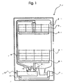
- Fig. 1 shows a household dishwasher 1 according to the invention
- the one Rinsing container 2 for holding items to be washed - usually dirty dishes and Cutlery - has, for example, in a dish rack 3 and one Dish rack 4 is classified.
- the liquid - commonly referred to as a rinse liquor - can be from one Circulation pump 7 via a liquid supply line 8 to an upper spray arm 5 and a liquid feed line 9 is conveyed to a lower spray arm 6.
- This liquid is usually at least in one sub-program step Rinsing program of the household dishwasher 1 through a continuous-flow heater 10 heated, with an inlet port 11 to the circulation pump 7 and with Output connector 12, 13 is connected to the liquid feed lines 8, 9.
- the Number of outlet connections corresponds to the number of spray devices or groups of sprayers operated simultaneously.
- the circulation pump 7 Pumped liquid is therefore in the embodiment of the inlet port 11 of the instantaneous water heater 10 and from its outlet connection 12, 13 via the Liquid feed lines 8, 9 directed to the spray devices 5, 6.
- Change-over device 14 can alternate between spray devices 5, 6 be filled with the liquid one after the other and / or continuously, what by opening one liquid outlet and by closing another liquid outlet is achieved.
- the liquid outlets of the reversing device 14 go here Embodiment directly into the outlet nozzle 12, 13 or with these identical.
- the reversing device 14 has a liquid inlet, which connects to the inlet connection 11 in the present exemplary embodiment or is formed by this.
- A can be used to close the liquid outlets Movable valve body from the liquid in the corresponding closed positions be directed.
- the reversing device 14 in the Household dishwashers either arranged on their own or directly on the circulation pump 7 must be connected.
- Fig. 2 shows a sectional view of the reversing device 14 of the household dishwasher 1 of Fig. 1.
- the reversing device 14 has a housing a preferably heart-shaped housing wall 14 'on the bottom in the Close the bottom of the liquid inlet 16 and the top of the roof the two Has liquid outlets 17, 18.
- the liquid outlets 17, 18 run in the present embodiment parallel to each other.
- Through the one on the left Liquid outlet 17 is the liquid 20 in the operation of the circulation pump Liquid supply line for the upper spray arm 5 pumped during the right arranged liquid outlet 18 for conveying the liquid 20 into the Liquid supply line is provided for the lower spray arm 6.
- valve body 15 Inside the housing is a preferably spherical valve body 15, whose density is greater than the density of the liquid 20, freely movable.
- This valve body 15 can have different closed positions B, C for closing the liquid outlets 17, 18 occupy, the closed position B on Liquid outlet 17 and the closed position C are at the liquid outlet 18.
- the valve body 15 is made of elastic material, at least on its surface an even better seal of the respective liquid outlet when taking the To reach locking positions B, C.
- the circulating pump sucks the liquid 20 in the operating state - e.g. Water - on and pumps them through the water heater 10 via the liquid inlet 16 into the housing the reversing device 14.
- the housing wall 14 At the transition of the liquid inlet 16 into the Interior of the housing, the housing wall 14 'is interrupted at the bottom, so that a or several wall pieces holding webs 19, 19 'to form a stable Represent starting position A for the valve body 15.
- the valve body 15 is in operation the circulation pump by the flow of the liquid 20 first of the Starting position A along the left inner wall in the closed position B on the roof of the Heart shape directed.
- the upper spray arm 5 is blocked and the water is over the open liquid outlet 18 to the lower spray arm 6 and from there to the Goods transported.
- This intermediate position D is preferably hook-shaped - similar to one in Skew arranged hockey stick - trained holding bridge 21 reached is preferably arranged at least approximately centrally in the housing and the counteracts further sinking of the valve body 15.
- the valve body 15 moves as a result of the Gravity from the closed position C along the right inner wall of the housing 14 'back to the starting position A, which in this case also a stable intermediate position for the renewed steering of the valve body 15 in the other closed position B.
- A represents resumption of pump operation.
- the Sealing points for the liquid outlets can be moved upwards so that result in nozzle-like bulges on the roof of the heart shape.
- the movement of the valve body by means of one of a Control device 22 - for example an actuator - adjustable adjusting element 23 - for example an actuator head - from the right inner wall of the housing be influenced in such a way that this from the closed position C back into the stable Intermediate position D when pump operation is switched off and from there again into the same Lock position C is steered when pump operation is switched on again.
- On Actuator is a drive means in which an electrically powered thermistor Mass - e.g. a wax mass - is heated and by which it is done Volume increase a piston that protrudes from the actuator Has actuator head is adjusted.
- the setting element 23 thus causes the sinking of the valve body 15 in the starting position A prevented, which a renewed - i.e. targeted consecutive - loading the upper spray arm over the open one Liquid outlet 17 results.
- valve body 15 Element 24 - see closed position B - attached by an outside on the Housing wall 14 'of the reversing device 14 attached reed switch 25 the exact position of the valve body 15 can be seen.
- This can target the Controlling movement of the valve body 15 in one or the other closed position be acted upon the decision to load the upper spray arm 5 or to influence the lower spray arm 6.
- Another variant uses one on the outside the housing wall mounted light barrier as a means of detection for the exact Valve body position.
- a speed-controlled circulation pump preferably a connection between a speed sensor and an electronic Control device for precise position detection.
- This takes advantage of the fact that after the pump has stopped based on the determined speed either from the speed sensor a round run of the pump due to the loading of the lower spray arm with a less liquid or an irregular flow of the pump because of the Feeding the upper spray arm with a larger amount of liquid recognized and reported to the electronic control device via a corresponding control signal becomes. From the notification of the non-circular running or the round running of the pump is the Position of the valve body 15 in the closed position C or B from the electronic Control device can be precisely and safely ascertained in an elegant manner without it mechanical or electromechanical means.
Landscapes
- Engineering & Computer Science (AREA)
- Water Supply & Treatment (AREA)
- Washing And Drying Of Tableware (AREA)
- Control Of Non-Positive-Displacement Pumps (AREA)
- Structures Of Non-Positive Displacement Pumps (AREA)
- Formation And Processing Of Food Products (AREA)
- Vending Machines For Individual Products (AREA)
Abstract
Description
- vom Boden der Herzform, an dem sich der Flüssigkeitseinlaß befindet, von einer Ausgangslage entlang der einen Innenwand in eine erste Verschlußstellung am Dach der Herzform, an dem sich die Flüssigkeitsauslässe befinden,
- von der ersten Verschlußstellung über die stabile Zwischenstellung in eine zweite Verschlußstellung,
- von der zweiten Verschlußstellung entlang der anderen Gehäusewand in die Ausgangslage. Diese Gehäuseform der Umsteuereinrichtung unterstützt besonders eine günstige und aufwandsarme Bewegung des Ventilkörpers zwischen den verschiedenen Stellungen.
- Fig. 1
- eine Haushalt-Geschirrspülmaschine in einer schematischen Darstellung, und
- Fig. 2
- eine Schnittdarstellung der Umsteuereinrichtung der erfindungsgemäßen Haushalt-Geschirrspülmaschine,
Claims (12)
- Haushalt-Geschirrspülmaschine miteinem Spülbehälter (2) zur Aufnahme von Spülgut und mindestens zwei Sprüheinrichtungen (5, 6) zum Beaufschlagen des Spülguts mit von einer Umwälzpumpe (7) geförderter Flüssigkeit (20),einer Umsteuereinrichtung (14) mit einem Flüssigkeitseinlaß (16) und jeweils an eine Sprüheinrichtung (5, 6) angeschlossenen Flüssigkeitsauslässen (17, 18), sowieeinem beweglichen Ventilkörper (15), der von der Flüssigkeit (20) in Verschlußstellungen (B, C) zum Verschließen der Flüssigkeitsauslässe (17, 18) gelenkt werden kann,
gekennzeichnet,
durch eine Umsteuereinrichtung (14), die derart ausgebildet ist, daß der Ventilkörper (15) von einer der Verschlußstellungen (B, C) bei Betrieb der Umwälzpumpe (7) in eine stabile Zwischenstellung (D, A) bei Abschalten der Umwälzpumpe (7) zurückbewegt wird und von dort bei Wiederaufnahme des Betriebs der Umwälzpumpe (7) in eine der Verschlußstellungen (C, B) gelenkt wird. - Haushalt-Geschirrspülmaschine nach Anspruch 1, dadurch gekennzeichnet, daß der Ventilkörper (15) von der Zwischenstellung (D, A) in eine andere Verschlußstellung (C, B) als die Verschlußstellung (B, C), die er vor der Zwischenstellung (D, A) eingenommen hat, gelenkt wird.
- Haushalt-Geschirrspülmaschine nach Anspruch 1, dadurch gekennzeichnet, daß der Ventilkörper (15) von der Zwischenstellung (D) in dieselbe Verschlußstellung (C), die er vor der Zwischenstellung (D) eingenommen hat, gelenkt wird.
- Haushalt-Geschirrspülmaschine nach Anspruch 3, dadurch gekennzeichnet, daß der Ventilkörper (15) mittels eines von einer Steuereinrichtung (22) einstellbaren Stellelements (23) in dieselbe Verschlußstellung (C) gelenkt wird.
- Haushalt-Geschirrspülmaschine nach einem der vorhergehenden Ansprüche, dadurch gekennzeichnet, daß auf dem Ventilkörper (15) ein magnetisches Element (24) und außen an dem Gehäuse der Umsteuereinrichtung (14) ein Reed-Schalter (25) zum Erkennen der Lage des Ventilkörpers (15) befestigt sind.
- Haushalt-Geschirrspülmaschine nach einem der Ansprüche 1 bis 3, dadurch gekennzeichnet, daß außen an dem Gehäuse der Umsteuereinrichtung (14) eine Lichtschranke zum Erkennen der Lage des Ventilkörpers (15) vorgesehen ist.
- Haushalt-Geschirrspülmaschine nach einem der Ansprüche 1 bis 3, dadurch gekennzeichnet, daß bei einer drehzahlgesteuerten Umwälzpumpe (7) ein Drehzahlsensor mit einer elektronischen Steuereinrichtung zum Erkennen der Lage des Ventilkörpers (15) verbunden ist.
- Haushalt-Geschirrspülmaschine nach einem der vorhergehenden Ansprüche, dadurch gekennzeichnet, daß die Umsteuereinrichtung (14) mindestens einen Haltesteg (21, 19, 19') für den Ventilkörper (15) zur Ausbildung der stabilen Zwischenstellung (D, A) aufweist.
- Haushalt-Geschirrspülmaschine nach Anspruch 8, dadurch gekennzeichnet, daß der Haltesteg (21) zumindest annähernd mittig im Gehäuseinneren der Umsteuereinrichtung (14) angeordnet ist.
- Haushalt-Geschirrspülmaschine nach Anspruch 8 oder 9, dadurch gekennzeichnet, daß der Haltesteg (21) hakenförmig ausgebildet ist.
- Haushalt-Geschirrspülmaschine nach Anspruch 8, dadurch gekennzeichnet, daß die Gehäusewand (14') am Boden derart unterbrochen ausgebildet ist, daß ein oder mehrere Wandstücke jeweils einen Haltesteg (19, 19') zur Ausbildung der mit einer Ausgangslage (A) identischen stabilen Zwischenstellung für den Ventilkörper (15) bilden.
- Haushalt-Geschirrspülmaschine nach einem der vorhergehenden Ansprüche, dadurch gekennzeichnet, daß die Umsteuereinrichtung (14) eine Gehäusewand (14') in Herzform aufweist, in dem der Ventilkörper (15) gelenkt wirdvom Boden der Herzform, an dem sich der Flüssigkeitseinlaß (16) befindet, von einer Ausgangslage (A) entlang der einen Innenwand in eine erste Verschlußstellung (B) am Dach der Herzform, an dem sich die Flüssigkeitsauslässe (17, 18) befinden,von der ersten Verschlußstellung (B) über die stabile Zwischenstellung (D) in eine zweite Verschlußstellung (C),von der zweiten Verschlußstellung (C) entlang der anderen Gehäusewand in die Ausgangslage(A).
Applications Claiming Priority (2)
| Application Number | Priority Date | Filing Date | Title |
|---|---|---|---|
| DE19947323 | 1999-10-01 | ||
| DE19947323A DE19947323A1 (de) | 1999-10-01 | 1999-10-01 | Haushalt-Geschirrspülmaschine |
Publications (2)
| Publication Number | Publication Date |
|---|---|
| EP1088509A1 true EP1088509A1 (de) | 2001-04-04 |
| EP1088509B1 EP1088509B1 (de) | 2007-05-02 |
Family
ID=7924160
Family Applications (1)
| Application Number | Title | Priority Date | Filing Date |
|---|---|---|---|
| EP00120950A Expired - Lifetime EP1088509B1 (de) | 1999-10-01 | 2000-09-26 | Haushalt-Geschirrspülmaschine |
Country Status (4)
| Country | Link |
|---|---|
| EP (1) | EP1088509B1 (de) |
| AT (1) | ATE361022T1 (de) |
| DE (2) | DE19947323A1 (de) |
| ES (1) | ES2285986T3 (de) |
Cited By (13)
| Publication number | Priority date | Publication date | Assignee | Title |
|---|---|---|---|---|
| EP1183985A3 (de) * | 2000-08-31 | 2002-10-30 | AEG Hausgeräte GmbH | Ventil für eine Geschirrspülmaschine mit einem beweglich angeordneten Verschliesselement |
| EP1230890A3 (de) * | 2001-02-13 | 2002-10-30 | AEG Hausgeräte GmbH | Verfahren und Vorrichtung zur Steuerung eines Ventiles einer Geschirrspülmaschine |
| EP1277431A1 (de) * | 2001-07-18 | 2003-01-22 | Electrolux Home Products Corporation N.V. | Haushaltgerät mit einer einstellbaren Flüssigkeitsverteilungseinrichtung und Verfahren zu deren Kontrolle |
| WO2003053211A1 (de) * | 2001-12-21 | 2003-07-03 | BSH Bosch und Siemens Hausgeräte GmbH | Geschirrspülmaschine mit einer umsteuereinrichtung |
| WO2004055388A1 (en) * | 2002-12-13 | 2004-07-01 | Actuant Corporation | Hydraulic tilting device for tilting the cab of a vehicle |
| WO2005058123A1 (de) * | 2003-11-25 | 2005-06-30 | Miele & Cie. Kg | Geschirrspülmaschine mit einer umwälzpumpe |
| EP1437082A3 (de) * | 2002-12-11 | 2005-08-03 | Lg Electronics Inc. | Geschirrspülmaschine und Vorrichtung zum Steuern des Spülwasserdurchfluss |
| DE202006015835U1 (de) * | 2006-10-16 | 2008-02-21 | Atb Umwelttechnologien Gmbh | Wegeventil |
| WO2008055811A1 (de) * | 2006-11-09 | 2008-05-15 | BSH Bosch und Siemens Hausgeräte GmbH | Verfahren zur desinfektion von leitungssystemen eines wasser-führenden haushaltsgeräts sowie derartiges haushaltsgerät |
| DE102007017274A1 (de) * | 2007-04-12 | 2008-10-30 | BSH Bosch und Siemens Hausgeräte GmbH | Verfahren zur Lageerkennung eines Verschlusselements in einer Wasserweiche |
| CN101262808B (zh) * | 2005-09-09 | 2011-01-26 | Bsh博世和西门子家用器具有限公司 | 家用洗碗机 |
| US8377220B2 (en) | 2007-08-31 | 2013-02-19 | Bsh Bosch Und Siemens Hausgeraete Gmbh | Dishwasher and method for operating a dishwasher |
| WO2013041432A1 (de) * | 2011-09-23 | 2013-03-28 | BSH Bosch und Siemens Hausgeräte GmbH | Schaltventil mit einem schwimmfähigen ventilschliesskörper und wasserführendes haushaltsgerät mit einem solchen schaltventil |
Families Citing this family (2)
| Publication number | Priority date | Publication date | Assignee | Title |
|---|---|---|---|---|
| DE102012216905A1 (de) * | 2012-09-20 | 2014-03-20 | BSH Bosch und Siemens Hausgeräte GmbH | Magnetventil mit magnetisierbarem Schwimmer |
| WO2024148746A1 (zh) * | 2023-01-13 | 2024-07-18 | 佛山市顺德区美的洗涤电器制造有限公司 | 分流器和洗碗机 |
Citations (4)
| Publication number | Priority date | Publication date | Assignee | Title |
|---|---|---|---|---|
| US4741353A (en) * | 1986-03-19 | 1988-05-03 | Industrie Zanussi, S.P.A. | Washing machine with improved liquid flow distributing valve |
| DE4404369A1 (de) * | 1994-02-11 | 1995-08-17 | Miele & Cie | Ventil, insbesondere Zulaufventil für den Sprüharm einer Geschirrspülmaschine |
| US5494062A (en) * | 1995-02-03 | 1996-02-27 | White Consolidated Industries, Inc. | Electromechanical controller for dishwasher with alternating flow |
| DE19857103A1 (de) * | 1998-12-10 | 2000-06-15 | Bsh Bosch Siemens Hausgeraete | Haushalt-Geschirrspülmaschine |
Family Cites Families (5)
| Publication number | Priority date | Publication date | Assignee | Title |
|---|---|---|---|---|
| US3279481A (en) * | 1964-08-31 | 1966-10-18 | Gen Motors Corp | Dishwasher with speed control means |
| US5108685A (en) * | 1990-12-17 | 1992-04-28 | Corning Incorporated | Method and apparatus for forming an article with multi-cellular densities and/or geometries |
| EP0780086A3 (de) * | 1995-12-22 | 1998-07-15 | White Consolidated Industries, Inc. | Wasser-Zufuhrrohr mit Behälter |
| US5899433A (en) * | 1996-03-16 | 1999-05-04 | Lg Electronics | Washing water supply control apparatus for dish washing machine |
| IT1305652B1 (it) * | 1998-01-13 | 2001-05-15 | Electrolux Zanussi Elettrodome | Lavastoviglie con dispositivi di spruzzatura azionabiliselettivamente |
-
1999
- 1999-10-01 DE DE19947323A patent/DE19947323A1/de not_active Withdrawn
-
2000
- 2000-09-26 EP EP00120950A patent/EP1088509B1/de not_active Expired - Lifetime
- 2000-09-26 DE DE50014290T patent/DE50014290D1/de not_active Expired - Lifetime
- 2000-09-26 AT AT00120950T patent/ATE361022T1/de not_active IP Right Cessation
- 2000-09-26 ES ES00120950T patent/ES2285986T3/es not_active Expired - Lifetime
Patent Citations (4)
| Publication number | Priority date | Publication date | Assignee | Title |
|---|---|---|---|---|
| US4741353A (en) * | 1986-03-19 | 1988-05-03 | Industrie Zanussi, S.P.A. | Washing machine with improved liquid flow distributing valve |
| DE4404369A1 (de) * | 1994-02-11 | 1995-08-17 | Miele & Cie | Ventil, insbesondere Zulaufventil für den Sprüharm einer Geschirrspülmaschine |
| US5494062A (en) * | 1995-02-03 | 1996-02-27 | White Consolidated Industries, Inc. | Electromechanical controller for dishwasher with alternating flow |
| DE19857103A1 (de) * | 1998-12-10 | 2000-06-15 | Bsh Bosch Siemens Hausgeraete | Haushalt-Geschirrspülmaschine |
Cited By (23)
| Publication number | Priority date | Publication date | Assignee | Title |
|---|---|---|---|---|
| EP1183985A3 (de) * | 2000-08-31 | 2002-10-30 | AEG Hausgeräte GmbH | Ventil für eine Geschirrspülmaschine mit einem beweglich angeordneten Verschliesselement |
| EP1230890A3 (de) * | 2001-02-13 | 2002-10-30 | AEG Hausgeräte GmbH | Verfahren und Vorrichtung zur Steuerung eines Ventiles einer Geschirrspülmaschine |
| EP1277431A1 (de) * | 2001-07-18 | 2003-01-22 | Electrolux Home Products Corporation N.V. | Haushaltgerät mit einer einstellbaren Flüssigkeitsverteilungseinrichtung und Verfahren zu deren Kontrolle |
| EP2052665A1 (de) * | 2001-07-18 | 2009-04-29 | Electrolux Home Products Corporation N.V. | Haushaltsgerät mit einer einstellbaren Flüssigkeitsverteilungseinrichtung und Verfahren zu deren Kontrolle |
| US7047986B2 (en) | 2001-12-21 | 2006-05-23 | Bsh Bosch Und Siemens Hausgeraete Gmbh | Movement reversal device, particularly for a dishwasher |
| WO2003053211A1 (de) * | 2001-12-21 | 2003-07-03 | BSH Bosch und Siemens Hausgeräte GmbH | Geschirrspülmaschine mit einer umsteuereinrichtung |
| US7237563B2 (en) | 2002-12-11 | 2007-07-03 | Lg Electronics Inc. | Dish washer and device for controlling washing water flow passage therein |
| EP1437082A3 (de) * | 2002-12-11 | 2005-08-03 | Lg Electronics Inc. | Geschirrspülmaschine und Vorrichtung zum Steuern des Spülwasserdurchfluss |
| NL1022163C2 (nl) * | 2002-12-13 | 2004-07-09 | Actuant Corp | Hydraulische klep. |
| US7252029B2 (en) | 2002-12-13 | 2007-08-07 | Actuant Corporation | Hydraulic tilting device for tilting the cab of a vehicle |
| CN1308598C (zh) * | 2002-12-13 | 2007-04-04 | 埃克徒安特公司 | 用于使汽车的驾驶室倾斜的液压倾斜装置 |
| WO2004055388A1 (en) * | 2002-12-13 | 2004-07-01 | Actuant Corporation | Hydraulic tilting device for tilting the cab of a vehicle |
| WO2005058123A1 (de) * | 2003-11-25 | 2005-06-30 | Miele & Cie. Kg | Geschirrspülmaschine mit einer umwälzpumpe |
| CN101262808B (zh) * | 2005-09-09 | 2011-01-26 | Bsh博世和西门子家用器具有限公司 | 家用洗碗机 |
| DE202006015835U1 (de) * | 2006-10-16 | 2008-02-21 | Atb Umwelttechnologien Gmbh | Wegeventil |
| WO2008055811A1 (de) * | 2006-11-09 | 2008-05-15 | BSH Bosch und Siemens Hausgeräte GmbH | Verfahren zur desinfektion von leitungssystemen eines wasser-führenden haushaltsgeräts sowie derartiges haushaltsgerät |
| US9131826B2 (en) | 2006-11-09 | 2015-09-15 | Bsh Hausgeraete Gmbh | Method for disinfecting conduit systems of a water-conducting appliance and such a household appliance |
| WO2008125482A3 (de) * | 2007-04-12 | 2009-02-26 | Bsh Bosch Siemens Hausgeraete | Verfahren zur lageerkennung eines verschlusselements in einer wasserweiche |
| CN101657138B (zh) * | 2007-04-12 | 2011-10-12 | Bsh博世和西门子家用器具有限公司 | 用于检测水分流器中的关闭元件的位置的方法 |
| US8295984B2 (en) | 2007-04-12 | 2012-10-23 | Bsh Bosch Und Siemens Hausgeraete Gmbh | Method for detecting the position of a closure element in a water distribution mechanism |
| DE102007017274A1 (de) * | 2007-04-12 | 2008-10-30 | BSH Bosch und Siemens Hausgeräte GmbH | Verfahren zur Lageerkennung eines Verschlusselements in einer Wasserweiche |
| US8377220B2 (en) | 2007-08-31 | 2013-02-19 | Bsh Bosch Und Siemens Hausgeraete Gmbh | Dishwasher and method for operating a dishwasher |
| WO2013041432A1 (de) * | 2011-09-23 | 2013-03-28 | BSH Bosch und Siemens Hausgeräte GmbH | Schaltventil mit einem schwimmfähigen ventilschliesskörper und wasserführendes haushaltsgerät mit einem solchen schaltventil |
Also Published As
| Publication number | Publication date |
|---|---|
| EP1088509B1 (de) | 2007-05-02 |
| DE50014290D1 (de) | 2007-06-14 |
| ES2285986T3 (es) | 2007-12-01 |
| DE19947323A1 (de) | 2001-04-05 |
| ATE361022T1 (de) | 2007-05-15 |
Similar Documents
| Publication | Publication Date | Title |
|---|---|---|
| EP1088509B1 (de) | Haushalt-Geschirrspülmaschine | |
| EP0943282B1 (de) | Geschirrspülmaschine | |
| EP1458277B2 (de) | Geschirrspülmaschine mit einer umsteuereinrichtung | |
| EP1997420A2 (de) | Gewerbliche Geschirrspülmaschine | |
| DE69933161T2 (de) | Versorgungsvorrichtung für einen in mittlerer Höhe eingebauten Sprüharm | |
| EP1833354A1 (de) | Geschirrspülmaschine | |
| DE2304035A1 (de) | Geschirrspuelmaschine mit einem oberen und einem unteren sprueharm | |
| EP1046369B1 (de) | Zweiwegeventil für ein flüssigkeitsführendes Haushaltgerät | |
| EP2394562A1 (de) | Wasserführendes Haushaltsgerät mit einer Zugabevorrichtung für Reinigungsmittel | |
| DE19947324A1 (de) | Haushalt-Geschirrspülmaschine | |
| DE102011077083B4 (de) | Geschirrspülmaschine, insbesondere Haushaltsgeschirrspülmaschine | |
| EP1835841A1 (de) | Geschirrspülmaschine | |
| EP2381827B1 (de) | Verfahren zum abpumpen einer flüssigkeit aus einem wasserführenden haushaltsgerät | |
| DE3440848C2 (de) | ||
| EP1926418B1 (de) | Haushalt-geschirrspülmaschine | |
| DE102006031555A1 (de) | Geschirrspülmaschine und Verfahren zu deren Steuerung | |
| DE4404369C2 (de) | Zulaufventil für den Sprüharm einer Geschirrspülmaschine | |
| DE3537970A1 (de) | Geschirrspuelmaschine | |
| DE102017217989B4 (de) | Haushalts-Geschirrspülmaschine | |
| DE19857101B4 (de) | Haushalt-Geschirrspülmaschine | |
| DE1928690A1 (de) | Automatische Geschirrspuelmaschine | |
| EP1029499B1 (de) | Haushalt-Geschirrspülmaschine | |
| DE102009028280B4 (de) | Haushaltsgerät | |
| DE102004054313A1 (de) | Verfahren zum Betreiben einer Geschirrspülmaschine und Geschirrspülmaschine zur Durchführung des Verfahrens | |
| DE4434235C1 (de) | Haushalt-Geschirrspülmaschine |
Legal Events
| Date | Code | Title | Description |
|---|---|---|---|
| PUAI | Public reference made under article 153(3) epc to a published international application that has entered the european phase |
Free format text: ORIGINAL CODE: 0009012 |
|
| AK | Designated contracting states |
Kind code of ref document: A1 Designated state(s): DE ES FR IT |
|
| AX | Request for extension of the european patent |
Free format text: AL;LT;LV;MK;RO;SI |
|
| 17P | Request for examination filed |
Effective date: 20011004 |
|
| AKX | Designation fees paid |
Free format text: DE ES FR IT |
|
| RAP1 | Party data changed (applicant data changed or rights of an application transferred) |
Owner name: BSH BOSCH UND SIEMENS HAUSGERAETE GMBH |
|
| 17Q | First examination report despatched |
Effective date: 20041206 |
|
| GRAP | Despatch of communication of intention to grant a patent |
Free format text: ORIGINAL CODE: EPIDOSNIGR1 |
|
| RBV | Designated contracting states (corrected) |
Designated state(s): AT BE CH CY DE DK ES FI FR GB GR IE IT LI LU MC NL PT SE |
|
| GRAS | Grant fee paid |
Free format text: ORIGINAL CODE: EPIDOSNIGR3 |
|
| GRAA | (expected) grant |
Free format text: ORIGINAL CODE: 0009210 |
|
| AK | Designated contracting states |
Kind code of ref document: B1 Designated state(s): AT BE CH CY DE DK ES FI FR GB GR IE IT LI LU MC NL PT SE |
|
| PG25 | Lapsed in a contracting state [announced via postgrant information from national office to epo] |
Ref country code: FI Free format text: LAPSE BECAUSE OF FAILURE TO SUBMIT A TRANSLATION OF THE DESCRIPTION OR TO PAY THE FEE WITHIN THE PRESCRIBED TIME-LIMIT Effective date: 20070502 |
|
| REG | Reference to a national code |
Ref country code: GB Ref legal event code: FG4D Free format text: NOT ENGLISH |
|
| REG | Reference to a national code |
Ref country code: CH Ref legal event code: EP |
|
| REG | Reference to a national code |
Ref country code: IE Ref legal event code: FG4D Free format text: LANGUAGE OF EP DOCUMENT: GERMAN |
|
| REF | Corresponds to: |
Ref document number: 50014290 Country of ref document: DE Date of ref document: 20070614 Kind code of ref document: P |
|
| PG25 | Lapsed in a contracting state [announced via postgrant information from national office to epo] |
Ref country code: SE Free format text: LAPSE BECAUSE OF FAILURE TO SUBMIT A TRANSLATION OF THE DESCRIPTION OR TO PAY THE FEE WITHIN THE PRESCRIBED TIME-LIMIT Effective date: 20070802 |
|
| ET | Fr: translation filed | ||
| NLV1 | Nl: lapsed or annulled due to failure to fulfill the requirements of art. 29p and 29m of the patents act | ||
| GBV | Gb: ep patent (uk) treated as always having been void in accordance with gb section 77(7)/1977 [no translation filed] |
Effective date: 20070502 |
|
| REG | Reference to a national code |
Ref country code: ES Ref legal event code: FG2A Ref document number: 2285986 Country of ref document: ES Kind code of ref document: T3 |
|
| REG | Reference to a national code |
Ref country code: IE Ref legal event code: FD4D |
|
| PG25 | Lapsed in a contracting state [announced via postgrant information from national office to epo] |
Ref country code: IE Free format text: LAPSE BECAUSE OF FAILURE TO SUBMIT A TRANSLATION OF THE DESCRIPTION OR TO PAY THE FEE WITHIN THE PRESCRIBED TIME-LIMIT Effective date: 20070502 Ref country code: NL Free format text: LAPSE BECAUSE OF FAILURE TO SUBMIT A TRANSLATION OF THE DESCRIPTION OR TO PAY THE FEE WITHIN THE PRESCRIBED TIME-LIMIT Effective date: 20070502 Ref country code: PT Free format text: LAPSE BECAUSE OF FAILURE TO SUBMIT A TRANSLATION OF THE DESCRIPTION OR TO PAY THE FEE WITHIN THE PRESCRIBED TIME-LIMIT Effective date: 20071002 |
|
| PLBE | No opposition filed within time limit |
Free format text: ORIGINAL CODE: 0009261 |
|
| STAA | Information on the status of an ep patent application or granted ep patent |
Free format text: STATUS: NO OPPOSITION FILED WITHIN TIME LIMIT |
|
| BERE | Be: lapsed |
Owner name: BSH BOSCH UND SIEMENS HAUSGERATE G.M.B.H. Effective date: 20070930 |
|
| 26N | No opposition filed |
Effective date: 20080205 |
|
| PG25 | Lapsed in a contracting state [announced via postgrant information from national office to epo] |
Ref country code: GR Free format text: LAPSE BECAUSE OF FAILURE TO SUBMIT A TRANSLATION OF THE DESCRIPTION OR TO PAY THE FEE WITHIN THE PRESCRIBED TIME-LIMIT Effective date: 20070803 Ref country code: MC Free format text: LAPSE BECAUSE OF NON-PAYMENT OF DUE FEES Effective date: 20070930 Ref country code: GB Free format text: LAPSE BECAUSE OF FAILURE TO SUBMIT A TRANSLATION OF THE DESCRIPTION OR TO PAY THE FEE WITHIN THE PRESCRIBED TIME-LIMIT Effective date: 20070502 |
|
| REG | Reference to a national code |
Ref country code: CH Ref legal event code: PL |
|
| PG25 | Lapsed in a contracting state [announced via postgrant information from national office to epo] |
Ref country code: CH Free format text: LAPSE BECAUSE OF NON-PAYMENT OF DUE FEES Effective date: 20070930 Ref country code: LI Free format text: LAPSE BECAUSE OF NON-PAYMENT OF DUE FEES Effective date: 20070930 |
|
| PG25 | Lapsed in a contracting state [announced via postgrant information from national office to epo] |
Ref country code: BE Free format text: LAPSE BECAUSE OF NON-PAYMENT OF DUE FEES Effective date: 20070930 |
|
| PG25 | Lapsed in a contracting state [announced via postgrant information from national office to epo] |
Ref country code: AT Free format text: LAPSE BECAUSE OF NON-PAYMENT OF DUE FEES Effective date: 20070926 |
|
| PG25 | Lapsed in a contracting state [announced via postgrant information from national office to epo] |
Ref country code: CY Free format text: LAPSE BECAUSE OF FAILURE TO SUBMIT A TRANSLATION OF THE DESCRIPTION OR TO PAY THE FEE WITHIN THE PRESCRIBED TIME-LIMIT Effective date: 20070502 |
|
| PG25 | Lapsed in a contracting state [announced via postgrant information from national office to epo] |
Ref country code: DK Free format text: LAPSE BECAUSE OF FAILURE TO SUBMIT A TRANSLATION OF THE DESCRIPTION OR TO PAY THE FEE WITHIN THE PRESCRIBED TIME-LIMIT Effective date: 20070802 Ref country code: LU Free format text: LAPSE BECAUSE OF NON-PAYMENT OF DUE FEES Effective date: 20070926 |
|
| REG | Reference to a national code |
Ref country code: DE Ref legal event code: R081 Ref document number: 50014290 Country of ref document: DE Owner name: BSH HAUSGERAETE GMBH, DE Free format text: FORMER OWNER: BSH BOSCH UND SIEMENS HAUSGERAETE GMBH, 81739 MUENCHEN, DE Effective date: 20150402 |
|
| REG | Reference to a national code |
Ref country code: ES Ref legal event code: PC2A Owner name: BSH HAUSGERATE GMBH Effective date: 20150527 |
|
| REG | Reference to a national code |
Ref country code: FR Ref legal event code: PLFP Year of fee payment: 16 |
|
| REG | Reference to a national code |
Ref country code: FR Ref legal event code: CD Owner name: BSH HAUSGERATE GMBH Effective date: 20151022 |
|
| REG | Reference to a national code |
Ref country code: FR Ref legal event code: PLFP Year of fee payment: 17 |
|
| PGFP | Annual fee paid to national office [announced via postgrant information from national office to epo] |
Ref country code: FR Payment date: 20160922 Year of fee payment: 17 |
|
| REG | Reference to a national code |
Ref country code: FR Ref legal event code: ST Effective date: 20180531 |
|
| PG25 | Lapsed in a contracting state [announced via postgrant information from national office to epo] |
Ref country code: FR Free format text: LAPSE BECAUSE OF NON-PAYMENT OF DUE FEES Effective date: 20171002 |
|
| PGFP | Annual fee paid to national office [announced via postgrant information from national office to epo] |
Ref country code: IT Payment date: 20190920 Year of fee payment: 20 |
|
| PGFP | Annual fee paid to national office [announced via postgrant information from national office to epo] |
Ref country code: DE Payment date: 20190930 Year of fee payment: 20 |
|
| PGFP | Annual fee paid to national office [announced via postgrant information from national office to epo] |
Ref country code: ES Payment date: 20191023 Year of fee payment: 20 |
|
| REG | Reference to a national code |
Ref country code: DE Ref legal event code: R071 Ref document number: 50014290 Country of ref document: DE |
|
| REG | Reference to a national code |
Ref country code: ES Ref legal event code: FD2A Effective date: 20210105 |
|
| PG25 | Lapsed in a contracting state [announced via postgrant information from national office to epo] |
Ref country code: ES Free format text: LAPSE BECAUSE OF EXPIRATION OF PROTECTION Effective date: 20200927 |