EP1084822A1 - Organische dünnfilme, deren herstellungsverfahren und ausrüstung dafür; ausrichtungslagen für flüssigkristalle, deren herstellungsverfahren und ausrüstung dafür; flüssigkristallanzeigen unter verwendung dieser ausrichtungslagen und deren herstellungsverfahren - Google Patents
Organische dünnfilme, deren herstellungsverfahren und ausrüstung dafür; ausrichtungslagen für flüssigkristalle, deren herstellungsverfahren und ausrüstung dafür; flüssigkristallanzeigen unter verwendung dieser ausrichtungslagen und deren herstellungsverfahren Download PDFInfo
- Publication number
- EP1084822A1 EP1084822A1 EP00902932A EP00902932A EP1084822A1 EP 1084822 A1 EP1084822 A1 EP 1084822A1 EP 00902932 A EP00902932 A EP 00902932A EP 00902932 A EP00902932 A EP 00902932A EP 1084822 A1 EP1084822 A1 EP 1084822A1
- Authority
- EP
- European Patent Office
- Prior art keywords
- molecules
- liquid crystal
- group
- substrate
- functional group
- Prior art date
- Legal status (The legal status is an assumption and is not a legal conclusion. Google has not performed a legal analysis and makes no representation as to the accuracy of the status listed.)
- Withdrawn
Links
Images


Classifications
-
- B—PERFORMING OPERATIONS; TRANSPORTING
- B32—LAYERED PRODUCTS
- B32B—LAYERED PRODUCTS, i.e. PRODUCTS BUILT-UP OF STRATA OF FLAT OR NON-FLAT, e.g. CELLULAR OR HONEYCOMB, FORM
- B32B9/00—Layered products comprising a layer of a particular substance not covered by groups B32B11/00 - B32B29/00
-
- B—PERFORMING OPERATIONS; TRANSPORTING
- B82—NANOTECHNOLOGY
- B82Y—SPECIFIC USES OR APPLICATIONS OF NANOSTRUCTURES; MEASUREMENT OR ANALYSIS OF NANOSTRUCTURES; MANUFACTURE OR TREATMENT OF NANOSTRUCTURES
- B82Y30/00—Nanotechnology for materials or surface science, e.g. nanocomposites
-
- B—PERFORMING OPERATIONS; TRANSPORTING
- B05—SPRAYING OR ATOMISING IN GENERAL; APPLYING FLUENT MATERIALS TO SURFACES, IN GENERAL
- B05D—PROCESSES FOR APPLYING FLUENT MATERIALS TO SURFACES, IN GENERAL
- B05D1/00—Processes for applying liquids or other fluent materials
- B05D1/18—Processes for applying liquids or other fluent materials performed by dipping
- B05D1/185—Processes for applying liquids or other fluent materials performed by dipping applying monomolecular layers
-
- B—PERFORMING OPERATIONS; TRANSPORTING
- B82—NANOTECHNOLOGY
- B82Y—SPECIFIC USES OR APPLICATIONS OF NANOSTRUCTURES; MEASUREMENT OR ANALYSIS OF NANOSTRUCTURES; MANUFACTURE OR TREATMENT OF NANOSTRUCTURES
- B82Y40/00—Manufacture or treatment of nanostructures
-
- C—CHEMISTRY; METALLURGY
- C03—GLASS; MINERAL OR SLAG WOOL
- C03C—CHEMICAL COMPOSITION OF GLASSES, GLAZES OR VITREOUS ENAMELS; SURFACE TREATMENT OF GLASS; SURFACE TREATMENT OF FIBRES OR FILAMENTS MADE FROM GLASS, MINERALS OR SLAGS; JOINING GLASS TO GLASS OR OTHER MATERIALS
- C03C17/00—Surface treatment of glass, not in the form of fibres or filaments, by coating
- C03C17/28—Surface treatment of glass, not in the form of fibres or filaments, by coating with organic material
- C03C17/30—Surface treatment of glass, not in the form of fibres or filaments, by coating with organic material with silicon-containing compounds
-
- G—PHYSICS
- G02—OPTICS
- G02F—OPTICAL DEVICES OR ARRANGEMENTS FOR THE CONTROL OF LIGHT BY MODIFICATION OF THE OPTICAL PROPERTIES OF THE MEDIA OF THE ELEMENTS INVOLVED THEREIN; NON-LINEAR OPTICS; FREQUENCY-CHANGING OF LIGHT; OPTICAL LOGIC ELEMENTS; OPTICAL ANALOGUE/DIGITAL CONVERTERS
- G02F1/00—Devices or arrangements for the control of the intensity, colour, phase, polarisation or direction of light arriving from an independent light source, e.g. switching, gating or modulating; Non-linear optics
- G02F1/01—Devices or arrangements for the control of the intensity, colour, phase, polarisation or direction of light arriving from an independent light source, e.g. switching, gating or modulating; Non-linear optics for the control of the intensity, phase, polarisation or colour
- G02F1/13—Devices or arrangements for the control of the intensity, colour, phase, polarisation or direction of light arriving from an independent light source, e.g. switching, gating or modulating; Non-linear optics for the control of the intensity, phase, polarisation or colour based on liquid crystals, e.g. single liquid crystal display cells
- G02F1/133—Constructional arrangements; Operation of liquid crystal cells; Circuit arrangements
- G02F1/1333—Constructional arrangements; Manufacturing methods
- G02F1/1337—Surface-induced orientation of the liquid crystal molecules, e.g. by alignment layers
- G02F1/133711—Surface-induced orientation of the liquid crystal molecules, e.g. by alignment layers by organic films, e.g. polymeric films
- G02F1/133719—Surface-induced orientation of the liquid crystal molecules, e.g. by alignment layers by organic films, e.g. polymeric films with coupling agent molecules, e.g. silane
Definitions
- the present invention relates to an organic thin film to be formed on a surface of a base material such as glass or ceramics, a manufacturing method thereof and a manufacturing apparatus thereof. Moreover, the invention relates to a liquid crystal alignment film having an alignment function for liquid crystal, a manufacturing method thereof a manufacturing apparatus thereof, a liquid crystal display device having the liquid crystal alignment film and a manufacturing method thereof.
- a method of manufacturing an organic thin film for example, a method of chemically adsorbing a chlorosilane series surface-active agent on a surface of a base material has been conventionally known. Details of this method are disclosed in, for example, Japanese Unexamined Patent Application Publication No. 3-7913 (1991), Japanese Unexamined Patent Application Publication No. 3-230156 (1991), Japanese Unexamined Patent Application Publication No. 4-330925 (1992), Japanese Patents No. 2, 028, 662, No. 2, 598, 867 and No. 2,638,446.
- chloroform has been conventionally used as a cleaning agent at the cleaning steps disclosed in the above publications. This is because chloroform has the following two remarkable features. Namely:1, a dissolving power for organic compound is large; and 2. since a boiling point is low, i.e., 61°C, chloroform can be easily removed by evaporation.
- the chloroform is highly toxic. Moreover, it is also known that the chloroform is a cause of breaking the ozone layer, and this substance put too much load on the environment.
- Japanese Unexamined Patent Application Publication Nos. 6-45142 (1994), 6-187692 (1994), 6-312477 (1994) and the like disclose ether, lactone, ester, nitril, amide and the like as a substitute cleaning agent for chloroform.
- these cleaning agents are open to question in a cleaning power. Actually these substitute cleaning agents are not used, and they are not excellent.
- a group of the present invention has been devised in order to solve the above problems in the prior arts, and its first object is to provide a method of manufacturing an organic thin film including a removing step using a cleaning agent other than a chlorine-based solvent, an organic thin film which is deposited by this method, and a manufacturing method to be used in this method.
- a group of the present invention has been devised in order to solve the problems in the prior arts, and its second object is to provide a method of manufacturing a liquid crystal alignment film including a removing step using a cleaning agent other than a chlorine-based solvent, a liquid crystal alignment film which is deposited by this method, and a manufacturing apparatus to be used in this method.
- its third object is to provide a liquid crystal display device having the liquid crystal alignment film, and a manufacturing method thereof.
- the inventors of the present invention have devoted themselves to examine an organic thin film manufacturing method.
- an organic thin film which is structured by coupling molecules to a surface of a base material, is cleaned or the like by a cleaning agent containing ketone, alkylene glycol or alkoxy alcohol, the molecules which are not coupled to the base material can be removed. Therefore, the inventors found out that this case provides the effect similar to that in the case where cleaning is executed by using a cleaning agent of a chlorine-based solvent, and completed the present invention.
- an organic thin film of the present invention composed of molecules bonded to a base material, is characterized in that the organic thin film is obtained so that after molecules having a functional group showing reactivity to a functional group having active hydrogen is brought into contact with and bonded to a surface of the base material, the molecules which are not bonded to the base material are removed by a cleaning agent which contains at least one selected from a group of ketone, alkylene glycol and alkoxy alcohol.
- the organic thin film having the above structure is composed of molecules which is arranged along the surface of the base material in a state that one end of the thin film is bonded to the surface of the base material and the other end is projected to a direction separating from the surface of the base material.
- the organic thin film which is constituted so that the molecules not bonded to the base material (hereinafter, occasionally referred as unfixed molecules) are removed by the cleaning agent, can obtain a uniform film structure without a state that molecules are disordered on the base material.
- the functional group showing reactivity to the functional group having active hydrogen can be one functional group selected from the functional groups represented by the following general formulas (1).
- A shows one kind of atom selected from a group composed of silicon, germanium, tin, titanium and zirconium.
- X shows one functional group selected from halogen, alkoxy group and isocyanate group.
- “on the base material” is not limited to the case where the molecules are directly fixed to the surface of the base material, and includes a case where the molecules are fixed via another substance layer.
- an organic thin film manufacturing method of the present invention is characterized by comprising: the film forming step of bringing molecules having a functional group showing reactivity to a functional group having active hydrogen into contact with a base material so as to be bonded onto the base material and forming a film composed of the molecules: and the removing step of removing the molecules which are not bonded onto the base material using a cleaning agent which contains at least one selected from a group of ketone, alkylene glycol and alkoxy alcohol.
- the molecules can have a functional group selected from the functional groups represented by the following general formulas (1).
- A shows one kind of atom selected from a group composed of silicon, germanium, tin, titanium and zirconium.
- X shows one kind of a functional group selected from halogen, alkoxy group and isocyanate group.
- the molecules having one functional group selected from the functional groups represented by the above general formulas (1) are fixed to the surface of the base material so that a film is formed at the film forming step, the molecules which are not bonded to the base material (unfixed molecules) remain on the surface of the film.
- the unfixed molecules can be easily removed by using the cleaning agent which contains at least one selected from a group of ketone, alkylene glycol and alkoxy alcohol. This is because the ketone or the like has excellent dissolving power with respect to unfixed molecules.
- the cleaning agent which contains at least one selected from a group of ketone, alkylene glycol and alkoxy alcohol.
- ketone at least one kind, of compound selected from a group of acetone, methyl ethyl ketone, diethyl ketone, methyl isobutyl ketone and acetylacetone can be used.
- the group of these compounds have excellent dissolving power with respect to molecules having one functional group selected from the functional groups represented by the above general formulas (1). Therefore, according to the above method using the group of compounds with excellent cleaning power, suitable ketone is selected as the need arises according to a type of the molecules and cleaning conditions so that an organic thin film with uniform thickness where the unfixed molecules are removed can be formed.
- alkylene glycol polyethylene glycol
- the polyethylene glycol has excellent dissolving power with respect to the compound having at least one functional group selected from the functional groups represented by the above general formulas (1). Therefore, according to the above method using polyethylene glycol with excellent cleaning power, unfixed molecules can be removed more easily so that an organic thin film from which the unfixed molecules are removed can be formed.
- a molecular weight of the polyethylene glycol can be within a range of not less than 100 to not more than 300.
- the cleaning agent one which does not include a chlorine-based solvent can be used.
- the cleaning agent which contains at least one selected from a group of ketone, alkylene glycol and alkoxy alcohol and does not include a chlorine-based solved
- a load to environment can be suppressed.
- this cleaning agent displays the cleaning effect equivalent to that of a conventional cleaning agent composed of a chlorine-based solvent for an object to be cleaned, namely, unfixed molecules, an organic thin film with uniform thickness can be formed. Therefore, an organic thin film with uniform thickness can be formed without using a chlorine-based solvent, and an organic thin film manufacturing process in which a load to environment is suppressed can be provided.
- the cleaning agent removing step of removing the cleaning agent adhering to the base material can be carried out.
- the cleaning agent remains on the formed organic thin film so that a bad influence can be prevented from being exerted on the quality of the film.
- a functional film having functions such as water-repellent effect and hydrophilic nature
- various functional deteriorations can be prevented.
- the cleaning agent removing step may include the rinse step of rinsing off the cleaning agent adhering to the base material with water, and the drying step of drying the water adhering to the base material.
- This method can clean the cleaning agent adhering to the film formed on the surface of the base material with water so as to remove it.
- a condensation reaction takes place between the AX group remaining on the film and water, and hydroxyl group can be introduced into the molecules composing the film.
- water adhering to the base material can be removed.
- dehydration reaction is activated between the bonded molecules on the surface of the base substrate so that a crosslinked structure can be obtained. Therefore, an organic thin film having excellent abrasion resistance, resistance to scratch and the like can be manufactured.
- a base material As the base material, a base material where a functional group having active hydrogen exists on its surface can be used.
- the film forming step and the removing step can be carried out in dry atmosphere.
- the film forming step When the film forming step is carried out in dry atmosphere, a monomolecular film if formed on the surface of the base material, and an accumulated film where a plurality of monomolecular film-like molecular layers are accumulated is formed on the monomolecular film. This is because the moisture in atmosphere reacts to the functional group represented by the above general formulas (1) and crosslinking is prevented. Since the removing step is carried for the film formed in such a manner in dry atmosphere, the whole accumulated film or some molecular layers of the accumulated film can be removed easily.
- the molecules having one functional group selected from the functional groups represented by the above general formulas (1) are fixed to become monomolecular film like so that an organic thin film can be formed.
- a monomolecular film-shaped organic thin film can be formed, a molecule design of the molecules having the functional group represented by the above general formulas (1) is controlled so that a film thickness can be easily controlled at molecule level. As a result, a very thin organic thin film can be manufactured so as to have a desired thickness.
- an organic thin film manufacturing apparatus of the present invention is characterized by comprising: film forming means for bringing molecules having a functional group showing reactivity to a functional group having active hydrogen into contact with a base material so as to be bonded onto a surface of the base material and forming a film composed of the molecules and removing means for removing the molecules which are not bonded onto the base material using a cleaning agent containing at least one selected from a group of ketone, alkylene glycol and alkoxy alcohol.
- the molecules have one functional group selected from the functional groups represented by the following general formulas (1).
- A shows one kind of atom selected from a group composed of silicon, germanium, tin, titanium and zirconium.
- X shows one functional group selected from halogen, alkoxy group and isocyanate group.
- a liquid crystal alignment film of the present invention which is composed of molecules bonded onto a substrate and where liquid crystal molecules being aligned in a specified direction, the is characterized in that the liquid crystal alignment film is obtained so that after molecules having a functional group showing reactivity to a functional group having active hydrogen are brought into contact with a surface of the substrate to be bonded thereto, the molecules which are not bonded to the substrate are removed by a cleaning agent containing at least one selected from a group of ketone, alkylene glycol and alkoxy alcohol.
- the liquid crystal alignment film having the above structure is composed of molecules which are arranged along the surface of the base material in a state that one end of the thin film is bonded to the surface of the base material and the other end is projected to a direction separating from the surface of the base material. Since this alignment film is a thin film which is cleaned by the above cleaning agent, unfixed molecules which are not bonded to the substrate are removed so that an uniform thickness can be obtained.
- liquid crystal molecules in its vicinity are inclined with respect to the substrate and/or restricted to an alignment direction.
- the ordered film structure that individual molecules are aligned uniformly has excellent alignment performance, and more concretely liquid crystal molecules can be aligned without disordering the alignment state.
- on the substrate is not limited to the case where the molecules are directly bonded to the surface of the substrate, and includes the case where the molecules are bonded via another substance layer such as an electrode.
- the functional group showing reactivity a functional group having active hydrogen can be one functional group selected from the functional groups represented by the following general formulas (1).
- A shows one kind of atom selected from a group composed of silicon, germanium, tin, titanium and zirconium.
- X shows one functional group selected from halogen, alkoxy group and isocyanate group.
- a liquid crystal alignment film manufacturing method of the present invention is characterized by comprising: film forming step of bringing molecules having a functional group showing reactivity to a functional group having active hydrogen into contact with a substrate to be bonded onto a surface of the substrate and forming a film composed of the molecules and removing step of removing the molecules which are not bonded to the substrate using a cleaning agent containing at least one selected from a group of ketone, alkylene glycol and alkoxy alcohol.
- the molecules can have one functional group selected from the functional groups represented by the following formulas (1).
- A shows one kind of atom selected from a group composed of silicon, germanium, tin, titanium and zirconium.
- X shows one functional group selected from halogen, alkoxy group and isocyanate group.
- the molecules having one functional group selected from the functional groups represented by the above general formulas (1) are fixed to the surface of the substrate so that the film is formed at the film forming step, unfixed molecules remains on the surface of the film. Since ketone or the like displays excellent dissolving power with respect tot he unfixed molecules, the unfixed molecules are cleaned by the above cleaning agent so as to be capable of being removed easily. Therefore, at least a liquid crystal alignment film composed of the molecules fixed onto the substrate can be formed on the surface of the substrate while a load to environment is being suppressed. Further, the liquid crystal alignment film formed in the above method has a uniform thickness and a film structure that the molecules are not disordered and are uniform.
- a liquid crystal alignment film manufacturing apparatus of the present invention is characterized by comprising: film forming means for bringing molecules having a functional group showing reactivity to a functional group having active hydrogen into contact with a substrate to be bonded to a surface of the substrate and forming a film composed of the groups of molecule; and removing means for removing the molecules which are not bonded to the substrate using a cleaning agent containing at least one selected from a group of ketone, alkylene glycol and alkoxy alcohol.
- the molecules can have one functional group selected from the functional groups represented by the following general formulas (1).
- A shows one kind of atom selected from a group composed of silicon, germanium, tin, titanium and zirconium.
- X shows one functional group selected from halogen, alkoxy group and isocyanate group.
- a liquid crystal display device of the present invention having a liquid crystal alignment film, in which the liquid crystal alignment film is constituted so that liquid crystal molecules are aligned on a substrate in a predetermined direction, is characterized in that: the liquid crystal alignment film is a thin film which is constituted so that molecules having a functional group showing reactivity to a functional group having active hydrogen are bonded onto the substrate, and after a group of the molecules are brought into contact with to be bonded to the substrate, the molecules which are not bonded to the substrate are removed by a cleaning agent containing at least one selected from a group of ketone, alkylene glycol and alkoxy alcohol.
- the liquid crystal alignment film of the liquid crystal display device with the above structure is a thin film cleaned by the above cleaning agent, the molecules which are not bonded to the substrate are removed so that the thin film has a uniform thickness.
- the liquid crystal alignment film is not a thin film cleaned by a conventional cleaning agent composed of a chlorine-based solvent, it has the ordered film structure that the molecules are aligned uniformly. Therefore, liquid crystal molecules can be aligned without disorder of the alignment state. Namely, due to the provision of the above-mentioned liquid crystal alignment film, alignment defect or the like of the liquid crystal is not visually recognized and display quality is excellent in the liquid crystal display device having the above structure.
- a liquid crystal display device manufacturing method of the present invention where the liquid crystal display device has the liquid crystal alignment film which is constituted so that liquid crystal molecules are aligned on a substrate in a predetermined direction, is characterized by comprising film forming step of bringing molecules having a functional group showing reactivity to a functional group having active hydrogen into contact with the substrate to be bonded onto a surface of the substrate and forming a film composed of the molecules; and removing step of removing the molecules which are not bonded to the substrate using a cleaning agent containing at least one selected from a group of ketone, alkylene glycol and alkoxy alcohol.
- a liquid crystal display device having a liquid crystal alignment film with uniform thickness and excellent alignment performance can be manufactured. Namely, when the above cleaning agent is used as a substitute cleaning agent of a chlorine-based cleaning agent, a liquid crystal display device with excellent display quality can be manufactured while a load to environment is being suppressed.
- An organic thin film manufacturing method is characterized by including: a film forming step of bringing molecules having a functional group showing reactivity to a functional group having active hydrogen into contact with a base material to be fixed onto a surface of the base material and forming a film composed of the molecules; and a removing step of removing the molecules which are not fixed to the base material using a cleaning agent including at least selected one kind of ketone, alkylene glycol and alkoxy alcohol.
- the molecules can be molecules having one functional group selected from the functional groups represented by the following general formulas (1).
- A shows one kind of atom selected from a group composed of silicon, germanium, tin, titanium and zirconium.
- X shows one functional group selected from halogen, alkoxy group and isocyanate group.
- halogen is F, Cl, Br and I, but Cl is preferable from a viewpoint of reactivity to the base material.
- the molecules having the functional group represented by the above general formulas (1) are composed by bonding the following functional groups to the functions group represented by the general formulas (1).
- an adsorption liquid that molecules having the functional group represented by the general formulas (1) (hereinafter, occasionally referred to as adsorption molecule or molecule) are dissolved in a nonaqueous organic solvent is prepared (chemisorption solution preparing step, S1). It is preferable that this chemisorption solution is prepared in a drying atmosphere that a relative humidity is within a range of not more than 35%, for example, in dry air, dry nitrogen or dry helium.
- the molecules having the functional group represented by the general formulas (1) are chemically adsorbed and fixed onto a surface of the base material 1 (see Fig. 4). More specifically, condensation reaction takes place between the molecules having the functional group represented by the general formulas (1) and a functional group having active hydrogen existing on the surface of the base material.
- the adsorbed molecules are molecules having -AX 3 group and the functional group having active hydrogen is hydroxyl group
- a reaction represented by the following chemical equation (2) takes place.
- A shows one kind of atom selected from a group composed of silicon, germanium, tin, titanium and zirconium.
- X shows one functional group selected from halogen, alkoxy group and isocyanate group.
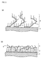
- a thin film 3 shown in Fig. 5(a) is formed on the surface of the base material 1. More specifically, adsorbed molecules which are adsorbed onto the surface of the base material 1 are bonded to non-adsorbed molecules which are not adsorbed onto the base material 1, and another non-adsorbed molecules are bonded to the above non-adsorbed molecules so that a chain is formed, and a polymer-like structure is formed. This chain bends so as to extend upward (into air) from the surface of the base material 1 and interlaces with another bent chain three-dimensionally so that the thin film 3 is formed.
- the thin film 3 having such a film structure is formed because of the following reasons. Namely, the non-adsorbed molecules which are not adsorbed onto the surface of the base material 1 react to moisture in the atmosphere so that HX molecules are eliminated. As a result, OH group is introduced into the non-adsorbed molecules. The OH group reacts or the like to the functional group (adsorbed portion) represented by the general formulas (1) in another non-adsorbed molecules so as to crosslink. Therefore, the thin film having the above structure is formed.
- a thickness of the thin film shown in the drawing is such that three monomolecular films composed of adsorbed molecules are laminated, and in this case, this film is referred to as three-molecular layer for the convenience.
- a monomolecular film 2 is formed on the surface of the base material 1, and non-adsorbed molecules 4 adhere to the surface of the monomolecular film 2 so that a thin film is formed.
- the adsorbed portion in the non-adsorbed molecules 4 does not react to moisture due to the dry atmosphere and adhere to base material in a state that it has the functional group represented by the general formulas (1).
- the method of bringing the molecules having the functional group represented by the general formulas (1) into contact with the surface of the base material 1 is not particularly limited, and for example, a method of soaking the base material 1 in an chemisorption solution previously prepared, a method of applying the chemisorption solution to the base material 1 or the like can be used.
- the functional group having active hydrogen existing on the surface of the base material 1 in addition to the hydroxyl group, for example, carboxyl group, sulfinic acid group, sulfonic acid group, phosphoric acid group, phosphorous acid group, thiol group, amino group and the like can be enumerated. Furthermore, a functional group that the active hydrogen of the above functional group is substituted by alkali metal or alkali earth metal may be used. Moreover, in the case where the functional group having active hydrogen does not exist on the surface of the base material 1 or few functional group exist, a compound oxidizing agent treatment such as an UV/ozone treatment, an oxygen plasma treatment or potassium permanganate solution is given. As a result, it is preferable that the surface of the base material 1 is reformed and the above functional group is introduced, or a number of the functional group is increased.
- a removing step is carried out (S3) using a cleaning agent containing at least one kind selected from a group of ketone, alkylene glycol and alkoxy alcohol.
- a main object to be cleaned at this step is groups of non-adsorbed molecules of the molecules having a functional group represented by the general formulas (1) which is not fixed by chemical linkage and remains on the surface of the base material 1. More specifically, in Fig. 5(a), the object to be cleaned is not the base material 1 but the non-adsorbed molecules which are bonded to adsorbed molecules as constitutional molecules in a network-like molecular layer 3 formed on the base material 1. Moreover, in Fig.
- the object to be cleaned is an accumulated film 5 composed of the non-adsorbed molecules 4 adhering to the surface of the monomolecular film 2.
- the groups of non-adsorbed molecules are dissolved in the cleaning agent so as to be removed, and a monomolecular film-like organic thin film having uniform thickness can be formed.
- the ketone as cleaning component contained in the cleaning agent has excellent solubility with respect to the molecules having a functional group represented by the general formulas (1).
- Examples of the ketone are acetone, methyl ethyl ketone, diethyl ketone, methyl isobutyl ketone and acetylacetone.
- examples of the alkylene glycol as cleaning component contained in the cleaning agent are ethylene glycol group, propylene glycol group and butylene glycol group.
- the ethylene glycol group is the most preferable of all.
- the ethylene glycol group has less stench and no color, and is characterized in that it easily blends with various organic solvents, water, surface-active agents and the like. Therefore, the ethylene glycol group is convenient to a design of the cleaning agents.
- the ethylene glycol group for example, ethylene glycol monoethyl ether, diethylene glycol monoethyl ether, diethylene glycol monoethyl ether acetate, ethylene glycol monoethyl ether acetate, ethylene glycol monomethyl ether, ethylene glycol monomethyl ether acetate, ethylene glycol mono-n-butyl ether, ethylene glycol monophenyl ether and the like can be used preferably.
- examples of the alkylene glycol may be polymers such as polyethylene glycol group, polypropylene glycol group, polybutylene glycol group. More specifically, as the polyethylene glycol group, for example, polyethylene glycol, polyethylene glycol monoethyl ether, polydiethylene glycol monoethyl ether, polydiethylene glycol monoethyl ether acetate, polyethylene glycol monoethyl ether acetate, polyethylene glycol monomethyl ether, polyethylene glycol monomethyl ether acetate, polyethylene glycol mono-n-butyl ether polyethylene glycol monophenyl ether and the like can be used suitable.
- polyethylene glycol group for example, polyethylene glycol, polyethylene glycol monoethyl ether, polydiethylene glycol monoethyl ether, polydiethylene glycol monoethyl ether acetate, polyethylene glycol monoethyl ether acetate, polyethylene glycol monomethyl ether, polyethylene glycol monomethyl
- the alkylene glycol is polymer
- its molecular weight is about not more than 2,000, more preferably it is within a range of 100 to 300. In the case where the molecular weight is larger than 2,000, viscosity becomes too large so that its handling property is deteriorated.
- polymer whose molecular weight is about not less than 300 it is the most suitable for the cleaning agent that the polymer is dissolved in water, alcohol or the like and it is used as a solution.
- density of polyethylene glycol is about 10 to 50 wt%.
- the density is about 10 to 50 wt%.
- the alkoxy alcohol is not particularly limited, and concretely, its examples are methoxy alcohol and ethoxy ethanol.
- the cleaning agent of the present invention may be a nonaqueous cleaning agent in which one of ketone, alkylene glycol and alkoxy alcohol is used solely.
- the removing step may be carried out in a dry atmosphere (relative humidity: not more than 35%).
- a dry atmosphere relative humidity: not more than 35%.
- a cleaning agent having low moisture content is preferably used. More concretely, when the moisture content is less than 1.0%, there arises no practical problem, but about less than 0.1% is preferable, and about less than 0.01% is more preferable. When the moisture content exceeds the above numerical value range, since AX group in the non-adsorbed molecules and adsorbed molecules reacts to water contained in the cleaning agent so that a crosslinking structure is formed, a monomolecular film cannot be formed also in this case.
- Examples of the concrete cleaning method executed at the removing step are a method of silently soaking the base material 1 in a cleaning tank filled with the cleaning agent as well as a method of applying a mechanical force to the base material 1 which is being soaked in the cleaning agent such as emitting a ultrasonic wave thereto, and a method of heating the cleaning agent in order to improve the cleaning power of the cleaning agent.
- a stress of the ultrasonic wave or the like is applied to the base material 1, it is necessary that the stress does not exert a bad influence on the base material 1.
- the cleaning conditions of the removing step are not particularly limited, they may be set properly as the need arises considering (a degree of adhesion of the non-adsorbed molecules to the object to be cleaned), a material of the object to be cleaned, form of the object to be cleaned and a bad influence on the thereafter steps.
- concentration of the cleaning agent, cleaning time and a number of cleaning times are changed, not only the monomolecular film-like organic thin film but also an organic thin film having a thickness equivalent to that of two molecular layers can be formed. Namely, a film thickness can be controlled. That is, a remaining degree of the non-adsorbed molecules is controlled so that the film thickness is controlled.
- the non-adsorbed molecules react to moisture in the air to be fixed, and for example, an organic thin film with a thickness equivalent to that of several molecular layers such as two-molecular layer is formed.
- a molecular design of adsorbed molecules to be allowed to adhere to the base material 1 is changed so that a thickness can be controlled accurately.
- a cleaning agent removing step of removing a cleaning agent may be carried out (S4).
- This cleaning agent removing step is mainly divided into a first cleaning agent removing method of rinsing a cleaning agent using a rinse agent and a second cleaning agent removing method of drying a cleaning agent to be evaporated.
- the first cleaning agent removing method can be adopted to the case where the cleaning agent contains at least one of ketone, alkylene glycol and alkoxy alcohol.
- the second cleaning agent removing method can be mainly adopted to the case where the cleaning agent contains ketone.
- the first cleaning agent removing method is composed of the rinse step of rinsing the cleaning agent using a rinse agent (S5), and the rinse agent drying step of evaporating the rinse agent to remove it (S6) (see Fig. 2).
- the first cleaning agent removing method is carried out preferably in the case where molecules where AX group remains are adsorbed to the surface of the base material 1, or in the case where a solvent having a comparatively high boiling point is used as the cleaning agent from the viewpoint of safety or the like.
- the rinse step is carried out in order that remaining cleaning agent is removed, and HX eliminating reaction is allowed to take place so that OH group is introduced into the adsorbed molecules (see Fig. 6(a)). Therefore, water is preferably used as the rinse agent.
- the second cleaning agent removing method includes a cleaning agent drying step (S7) of evaporating a cleaning agent to be evaporated (S7), and a contact step of bringing the base material 1 into contact with moisture (S8), and a drying step of drying the moisture (S9) (see Fig. 3).
- the second cleaning agent removing method is preferably executed in the case where a low-boiling point cleaning agent such as acetone and methyl ethyl ketone which is evaporated at normal temperature is used.
- the contact step is executed in order to allowing AX group remaining in the molecules adsorbed on the surface of the the base material 1 react with moisture and introduce OH group into the adsorbed molecules.
- the method of bringing the base material 1 into contact with moisture for example, a method of leaving the base material 1 in air and allowing the base material 1 to react with moisture in the air, or a method of allowing the base material 1 to directly react with water is adopted. Thereafter, the drying step (S9) is carried out, and dehydration reaction takes place between OH groups so that an organic thin film having a crosslinking structure can be formed.
- the cleaning agent may be simply dried after the removing step.
- one kind of material selected from a group of glass, metal, metal oxide, ceramics, plastic, timber, stone, fabric, paper, polymeric resin and the like can be applied to the base material 1.
- the surface of the base material 1 is painted with coating compound.
- the base materials made of the above materials have similar physical properties in that a functional group having active hydrogen exists on their surfaces.
- plastic is particularly used as the material of the base material 1, it is considered that the property of the base material is changed depending on a type of plastic or the base material 1 is damaged due to dissolving or the like. Therefore, it is necessary to use a cleaning agent after previously ensuring that the cleaning agent does not have the above affects on the base material 1 made of plastic.
- the inventors of the present invention have disclosed a chemisorption film where film density is improved and a manufacturing method thereof in Japanes Patent No. 2,598,867.
- adsorption reaction and cleaning for removing unreacted non-adsorbed molecules are repeated alternatively so that a chemisorption agent is fixed to a base body and a chemically adsorbed film, and a chemically adsorbed film having high density is formed.
- a nonaqueous solvent is used for the cleaning, but the chemisorption film to be formed has a film structure which is different form that of the organic thin film devised by the inventors in the following points.
- the chemically adsorbed film formed by the above method since chemisorption graft molecules are bonded to chemisorption backbone molecules first adsorbed to the base material even in a portion of the surface of the base material where a functional group having active hydrogen does not exist, a distance between molecules of the chemically adsorbed film becomes short so that a structure with high density is obtained. Furthermore, since hydroxyl group which is not used for bonding to the chemisorption backbone molecules or the like are being still bonded to the chemisorption graft molecules, a lot of hydroxyl group remains in the chemisorption film.
- the organic thin film of the present invention since most of the film forming molecules are adsorbed to the surface of the base material, its density is lower than that of the chemisorption film. Moreover, since the drying step is carried out in the manufacturing process and dehydration reaction is allowed to take place between the hydroxyl groups existing in the film so that the hydroxyl groups are crosslinked, there is a low expectation that hydroxyl group exists in the organic thin film in comparison with the chemisorption film.
- the present invention establishes the manufacturing process as for the organic thin film having the film structure essentially different from that of the chemisorption film disclosed in the above publication.
- an organic thin film manufacturing apparatus of the present invention is composed of film forming means and removing means (see Fig. 7).
- base material delivery means 52 composed of a conventionally known carrier apparatus, for example, can be disposed between the film forming means and the removing means.
- the film forming means has a function that an chemisorption solution is applied to a base material and groups of adsorbed molecules included in the chemisorption solution are adsorbed and fixed onto the base material so that a film is formed.
- a spinning or roller type coating applicator or the like can be used as the film forming means.
- the removing means has a function that an object to be cleaned is cleaned by a cleaning agent including at least one selected from a group of ketone, alkylene glycol and alkoxy alcohol.
- a cleaning agent including at least one selected from a group of ketone, alkylene glycol and alkoxy alcohol.
- the object to be cleaned is non-adsorbed molecules which adhere to and remain on the base material (unfixed molecules).
- the film forming means and the removing means may be constituted so as to be included in one closed system, or they may be disposed independently.
- the film forming means and removing means are in the one closed system so as to be capable of being isolated from the external air.
- the film forming step and the removing step can be carried out in a dry atmosphere (Fig. 7(a)).
- the constitution that the film forming means and the removing means are in the one closed system means that, for example, air shielding means 51 in which the film forming means and removing means can be disposed is included in the organic thin film manufacturing apparatus.
- the air shielding means 51 is not particularly limited as long as it can isolate the external air from the inside, and for example, a chamber, a processing room or the like which can control temperature, humidity and the like can be provided.
- convection control means which can, needless to say, control humidity as well as inner convection at normal temperature and pressure, can be provided.
- inner humidity and convection state can be controlled, and working safety can be secured.
- the working safety is necessary because when a compound with small molecular weight of ketone, alkylene glycol or alkoxy alcohol is used, a cleaning agent containing them requires special care due to its flammability.
- the film forming means and the removing means can be constituted as processing units which are separated and independent from each other (Fig. 7(b)).
- air shielding means may be disposed for each processing unit so that those means can be isolated form the air and can control humidity and the like.
- the removing means may be of batch processing system or flow processing system.
- a soaking method or the like of soaking a base material as an object to be cleaned can be used.
- the cleaning agent 32 is poured into a cleaning tank 31 and base materials 34 are placed in a cassette 33, and the cassette 33 is soaked in the cleaning tank 31 for predetermined time so that the base materials 34 are cleaned.
- a cleaning apparatus which is composed of a carrier section 41 for carrying the base materials 34 and a plurality of injection devices 42 for injecting a cleaning agent, can be used.
- the injection devices 42 are composed of a gate arch-shaped main body section 43 and nozzles 43 for injecting the cleaning agent like spray or droplet.
- the nozzles 43 are provided so that the injection direction of the cleaning agent is the same as a down direction.
- the carrier section 41 is provided so as to be inside the gate arch-shaped main body section 43.
- the base materials 34 placed on the carrier section 41 are carried to a direction of an arrow A, and the cleaning agent is injected from the nozzles 44 so that the base materials 34 are cleaned.
- the above-mentioned batch processing system and the flow processing system are only examples, and the present invention is not limited to the above means. Any techniques which have the structure substantially same as the technical idea described in claims of the present invention and the similar functions and effects are included in the technical scope of the present invention.
- the organic thin film manufacturing apparatus of the present invention can be provided with cleaning agent removing means so that the cleaning agent removing step of removing the cleaning agent adhering to the base material is carried out as the need arises (Figs. 7(a) and 7(b)).
- the cleaning agent removing means as shown in Fig. 7(c), may have rinse means and drying means.
- the rinse means is not particularly limited, and conventionally known various rinse apparatuses can be used.
- the drying means is not particularly limited, and conventionally known various drying apparatuses can be used. As the drying means, blow by means of normal temperature wind or warm wind can be suitably adopted.
- the organic thin film of the present invention is applied as the liquid crystal alignment film to a liquid crystal display device
- the organic thin film can be manufactured by the following method.
- a substrate, on which electrodes or the like made of ITO (indium tin oxide) are formed according to the above-mentioned procedure is brought into contact with the chemisorption solution so that the adsorbed molecules are adsorbed (S2, see Fig. 1).
- the adsorbed molecules can be adsorbed onto the surface of ITO because OH group exists on the surface of ITO, and the adsorbed molecules has a functional group showing reactivity to a functional group having active hydrogen such as OH group. As a result, a thin film with excellent peeling resistance can be formed.
- non-adsorption molecules remaining on the surface of the substrate are cleaned and removed at S3.
- the remaining non-adsorption molecules are removed so that a thin film with uniform thickness can be formed. Therefore, turbulence of the alignment state of liquid crystal due to the remaining non-adsorption molecules, namely, an alignment defect can be suppressed.
- a conventional cleaning agent such as chloroform
- the cleaning is carried out by using the cleaning agent containing one selected from the group of ketone, alkylene glycol and alkoxy alcohol, the turbulence of the adsorbed state of the adsorbed molecules hardly occurs, and an ordered film structure that the groups of adsorbed molecules align uniformly can be obtained.
- the cleaning agent is removed or the like at S4 so that the liquid crystal alignment film of the present invention can be manufactured.
- the liquid crystal alignment film may be subject to an aligning treatment such as a rubbing treatment as the need arises.
- the liquid crystal alignment film manufacturing method of the present invention can form a liquid crystal alignment film having uniform thickness without using a chlorine-based cleaning agent while a load to environment is being suppressed.
- the liquid crystal display device of the present invention can be constituted so as to have a first substrate 61, a second substrate 62 which twins with the first substrate 61, and a liquid crystal layer 63 which intervenes between the first substrate 61 and the second substrate 62.
- TFT (thin film transistor) groups 64 and first electrodes 65 are formed on an inner side of the first substrate 61, and a liquid crystal alignment film 66 is formed on the first electrode 65.
- a color filter 67 is formed on an inner surface of the second substrate 62, and a second electrode 68 is formed on the second substrate 62 and the color filter 67.
- a liquid crystal alignment film 69 is formed on the second electrode 68. Moreover, the first substrate 61 and the second substrate 62 are bonded by a seal member 70 so that liquid crystal is sealed and held in a panel.
- a polarization plate 71 is provided on an outer side of the first substrate 61, and a polarization plate 72 is provided on an outer side of the second substrate 62.
- the first substrate 61 and the second substrate 62 are transparent substrates made of glass, for example.
- the first electrode 65 and the second electrode 68 are transparent conductive film made of ITO, for example.
- the liquid crystal layer 63 is constituted so as to include nematic liquid crystal, for example.
- the color filter 67 is constituted so as to include dots of R (red), G (green) and B (blue).
- the alignment defect or the like of liquid crystal is not visually recognized so that excellent display quality can be provided. This is because, as mentioned above, the thickness of the liquid crystal alignment film is uniform and the film structure that the groups of adsorbed molecules are adsorbed uniformly is obtained, and thus excellent aligning performance is displayed so that liquid crystal molecules can be aligned without disorder of the alignment state.
- liquid crystal display device having the above structure can be manufactured by adopting a conventional known method except that liquid crystal alignment films 66 and 69 are deposited by the above-mentioned method.
- the liquid crystal alignment film manufacturing apparatus according to the present invention can have the structure similar to that of the above-mentioned organic thin film manufacturing apparatus. Therefore, the detailed explanation thereof is omitted.
- n-octadecyl trichlorosilane was dissolved in hexadecane so as to be about 1 weight%, and an chemisorption solution A was prepared.
- a glass substrate 11 (2 cm ⁇ 5 cm, thickness: 1.1 mm) which was subject to degreasing cleaning sufficiently was soaked in the chemisorption solution A for 1 hour.
- a dehydrochlorination reaction represented by the following chemical equation took place between hydroxyl group existing on the surface of the glass substrate 11 and trichloroxyl group, and the chemisorption solution A was chemisorbed onto the glass substrate 11 via siloxane bond.
- a sufficient amount (50 ml to 100 ml) of acetone as a cleaning agent was poured into a cleaning tank in air of relative humidity of about 35% and was heated at about 45°C.
- the glass substrate 11 was sufficiently cleaned in the cleaning tank. Further, the glass substrate 11 was rinsed sufficiently in order to rinse off polyethylene glycol which adhered to the surface of the glass substrate 11 with water. As a result, the cleaning agent is rinsed off, and unreacted Cl group in molecules chemisorbed onto the glass substrate 11 is substituted by OH group.
- the glass substrate 11 was dried. As a result, a dehydration reaction took place between the OH groups and the OH groups were crosslinked so that a monomolecular film 12 shown in Fig. 10 was formed on the glass substrate.
- FT-IR Fourier transform infrared spectroscopy method
- a signal which is distinctive in 2930 to 2840 cm -1 (attribute: CH 3 and -CH 2 -), 1470 cm -1 (attribute: -CH 2 -), and 1080 cm -1 (attribute: -Si-O-), could be obtained.
- FT-IR Fourier transform infrared spectroscopy method
- the removing step in the present embodiment may be carried out in dry air with relative humidity of not more than 5% or in nitrogen, but the satisfactory result could be obtained in air with relative humidity of not more than 35%.
- the steps similar to those in the embodiment 1-1 except that methyl ethyl ketone (50 ml to 100 ml) was used as a cleaning agent were carried out so that the monomolecular film 12 was disposed on the glass substrate 11.
- methyl ethyl ketone 50 ml to 100 ml
- a signal with adsorption strength approximately same as that in Fig. 11 was be obtained in the position approximately same as that in Fig. 11.
- the glass substrate 11 which was sufficiently degreased and cleaned was soaked in the chemisorption solution B for 1 hour in a nitrogen atmosphere.
- the molecules represented by the above chemical equation (4) were chemisorbed onto the brass substrate 11 as represented by the following chemical equation (5).
- acetone 50 ml to 100 ml
- the glass substrate 11 was sufficiently cleaned in the cleaning tank.
- the glass substrate 11 was sufficiently rinsed in order to rinse off the acetone adhering to the surface of the glass substrate 11 with water.
- the cleaning agent is rinsed off, and unreacted Cl group in the molecules chemisorbed onto the glass substrate 11 is substituted by OH group.
- the glass substrate 11 was dried. As a result, the OH groups are dehydrated to be crosslinked, and a monomolecular film 13 shown in Fig. 13 was formed on the glass substrate 11.
- the embodiment 1-3 was compared with the comparative example 1-2 in detail, the following different points in the film structures were found out. That is, in the absorption spectrums shown in Figs. 14 and 15, absorption to CH 2 of 2920 cm -1 resulted from asymmetric stretching vibration was compared with absorption to CH 2 of 2860 cm -1 resulted from symmetric stretching vibration, the absorption ratio became 2.1:1 in Fig. 14 of the embodiment 1-3 and 1.9:1 in Fig. 15 of the comparative example 1-2. Therefore, it was found that the monomolecular film of the embodiment 1-3 has the film structure which is more uniform and ordered than that of the monomolecular film of the comparative example 1-2.
- the steps similar to those in the embodiment 1-3 except that ethyl acetate or ethyl formate was used as a cleaning agent were carried out so that the monomolecular film 13 was deposited on the glass substrate 11.
- the surface of the glass substrate 11 got a nebula in an instant so that a transparent thin film could not be deposited.
- the ethyl acetate, and ethyl formate are ester group disclosed in Japanese Unexamined Patent Application Publication Nos. 6-45142 (1994), 6-312477 (1994), 6-187692 (1994) and the like.
- n-octadecyl trichlorosilane of about 1 weight% was dissolved in hexadecane so that an chemisorption solution A was prepared.
- a glass substrate 21 (20 ⁇ 7 mm, thickness: 1.1 mm) which was subject to degreasing cleaning sufficiently was soaked in the chemisorption solution A for 1 hour.
- dehydrochlorination reaction represented by the following chemical equation took place between hydroxyl group existing on the surface of the glass substrate 21 and trichloroxyl group so that the chemisorption solution A was chemisorbed onto the glass substrate 21 via siloxane bond.
- polyethylene glycol average molecular weight: 300
- 50 ml an amount that the glass substrate 21 is soaked therein sufficiently and shaking-off cleaning is possible
- the glass substrate 21 was cleaned in the cleaning tank three times. Cleaning time required for the cleaning at a time was about 1 minute.
- the glass substrate 21 was rinsed in order to rinse off polyethylene glycol which adhered to the surface of the substrate 21 with water. The rinsing was conducted by leaving the glass substrate 11 in flowing water for 5 minutes.
- the cleaning agent is rinsed off, and unreacted Cl group in the molecules chemisorbed to the glass substrate 21 is substituted by OH group.
- the glass substrate 21 was dried.
- the OH groups are dehydrated so as to be crosslinked, and a monomolecular film 22 shown in Fig. 18 was formed on the glass substrate 21.
- FT-IR Fourier transform infrared spectroscopy method
- a signal which is distinctive in 2930 to 2840 cm -1 (attribute: CH 3 and -CH 2 -), 1470 cm -1 (attribute: -CH 2 -), and 1080 cm -1 (attribute: -Si-O-), could be obtained.
- FT-IR Fourier transform infrared spectroscopy method
- the removing step in the present embodiment may be carried out in dry air with relative humidity of not more than 5% or in nitrogen, but the satisfactory result could be obtained in air with relative humidity of not more than 35%.
- the steps similar to the above embodiment 2-1 except that chloroform was used as a cleaning agent were carried out so that the monomolecular film 22 was deposited on the glass substrate 21.
- this monomolecular film 22 was subject to FT-IR measurement, as shown in Fig. 20, a signal with absorption strength approximately same as that of the absorption spectrum shown in Fig. 20 could be obtained in the absorption position approximately same as that of the absorption pectrum shown in Fig. 19.
- the glass substrate 21 which was sufficiently degreased and cleaned was soaked in the chemisorption solution B for 1 hour in a nitrogen atmosphere.
- the molecules represented by the above chemical equation (4) were chemisorbed onto the brass substrate 21 as represented by the following chemical equation (5).
- glycol ether product name: PK-LCG55, made by Parker Corporation
- average molecular weight: 200 average molecular weight: 200
- the glass substrate 21 was sufficiently cleaned in the cleaning tank. Further, the glass substrate 21 was sufficiently rinsed in order to rinse off the polyethylene glycol adhering to the surface of the glass substrate 21. As a result, the cleaning agent is rinsed off, and unreacted Cl group in the molecules chemisorbed onto the glass substrate is substituted by OH group.
- the glass substrate 21 was dried. As a result, the OH groups are dehydrated to be crosslinked, and a monomolecular film 23 shown in Fig. 21 was formed on the glass substrate 21.
- the steps similar to those in the embodiment 2-2 except that chloroform was used as a cleaning agent were carried out so that the monomolecular film 23 was deposited on the glass substrate 21.
- this monomolecular film 23 was subject to the FT-IR measurement, as shown in Fig. 23, a signal with absorption strength approximately same as that in Fig. 22 was obtained in a position approximately same as that in Fig. 22.
- the embodiment 2-2 was compared with the comparative example 2-2 in detail, the following different points in the film structures were found out. That is, in the absorption spectrums shown in Figs. 22 and 23, absorption to CH 2 of 2920 cm -1 resulted from asymmetric stretching vibration was compared with absorption to CH 2 of 2860 cm -1 resulted from symmetric stretching vibration, the absorption ratio became 1.8:1 in Fig. 22 of the embodiment 2-2 and 1.7:1 in Fig. 23 of the comparative example 2-2. Therefore, it was found that the monomolecular film of the embodiment 2-2 has the film structure which is more uniform and ordered than that of the monomolecular film of the comparative example 2-2.
- the steps similar to those in the embodiment 2-2 except that ethoxy ethanol was used as a cleaning agent were carried out so that the monomolecular film 23 was deposited on the glass substrate 21.
- this monomolecular film 23 was subject to the FT-IR measurement, as shown in Fig. 24, a signal with absorption strength approximately same as that in Figs. 22 and 23 could be obtained in a position approximately same as that in Figs. 22 and 23.
- the organic thin film of the present invention since the organic thin film is formed by cleaned by the cleaning agent containing at least one selected from the group of ketone, alkylene glycol and alkoxy alcohol, the film structure with uniform thickness which is aligned uniformly and is ordered can be obtained.
- the cleaning agent which contains at least one selected from the group of ketone, alkylene glycol and alkoxy alcohol is used so that unfixed molecules can be removed by using this cleaning agent as substitute cleaning agent of a chlorine-based solvent.
- the organic thin film having uniform thickness can be manufactured.
- the organic thin film manufacturing process which reduces a load to environment can be provided.
- liquid crystal alignment film of the present invention since this alignment film has the film structure where the thickness is uniform and molecules are aligned uniformed and ordered, liquid crystal molecules can be aligned without disturbing the alignment state.
- the cleaning agent which contains at least one selected from the group of ketone, alkylene glycol and alkoxy alcohol is used so that unfixed molecules can be removed without using a chlorine-based organic solvent, and the liquid crystal alignment film with uniform thickness can be manufactured.
- the liquid crystal alignment film which has the adsorption state with respect to a substrate and excellent alignment function, can be manufactured while a load to environment is being reduced without disordering the film structure.
- liquid crystal display device having such a liquid crystal alignment film can produce the effect that alignment defect or the like of liquid crystal is not visually recognized and display quality is excellent. Therefore, the industrial significance of the present invention is great.
Priority Applications (1)
| Application Number | Priority Date | Filing Date | Title |
|---|---|---|---|
| EP01200513A EP1132147A3 (de) | 1999-02-10 | 2000-02-10 | Organische Dünnfilme, deren Herstellungsverfahren und Ausrüstung dafür |
Applications Claiming Priority (5)
| Application Number | Priority Date | Filing Date | Title |
|---|---|---|---|
| JP3345999 | 1999-02-10 | ||
| JP3345999 | 1999-02-10 | ||
| JP6080899 | 1999-03-08 | ||
| JP6080899 | 1999-03-08 | ||
| PCT/JP2000/000776 WO2000047403A1 (fr) | 1999-02-10 | 2000-02-10 | Minces films organiques, procede de production de ceux-ci et equipement prevu a cet effet; couches d'alignement pour cristaux liquides, procede de production de ceux-ci et equipement prevu a cet effet;et ecrans d'affichage a cristaux liquides fabriques a l'aide de ces couches d'alignement et procede de production de ceux-c |
Related Child Applications (1)
| Application Number | Title | Priority Date | Filing Date |
|---|---|---|---|
| EP01200513A Division EP1132147A3 (de) | 1999-02-10 | 2000-02-10 | Organische Dünnfilme, deren Herstellungsverfahren und Ausrüstung dafür |
Publications (1)
| Publication Number | Publication Date |
|---|---|
| EP1084822A1 true EP1084822A1 (de) | 2001-03-21 |
Family
ID=26372156
Family Applications (2)
| Application Number | Title | Priority Date | Filing Date |
|---|---|---|---|
| EP00902932A Withdrawn EP1084822A1 (de) | 1999-02-10 | 2000-02-10 | Organische dünnfilme, deren herstellungsverfahren und ausrüstung dafür; ausrichtungslagen für flüssigkristalle, deren herstellungsverfahren und ausrüstung dafür; flüssigkristallanzeigen unter verwendung dieser ausrichtungslagen und deren herstellungsverfahren |
| EP01200513A Withdrawn EP1132147A3 (de) | 1999-02-10 | 2000-02-10 | Organische Dünnfilme, deren Herstellungsverfahren und Ausrüstung dafür |
Family Applications After (1)
| Application Number | Title | Priority Date | Filing Date |
|---|---|---|---|
| EP01200513A Withdrawn EP1132147A3 (de) | 1999-02-10 | 2000-02-10 | Organische Dünnfilme, deren Herstellungsverfahren und Ausrüstung dafür |
Country Status (4)
| Country | Link |
|---|---|
| EP (2) | EP1084822A1 (de) |
| KR (1) | KR20010042451A (de) |
| CN (1) | CN1293614A (de) |
| WO (1) | WO2000047403A1 (de) |
Cited By (3)
| Publication number | Priority date | Publication date | Assignee | Title |
|---|---|---|---|---|
| FR2840297A1 (fr) * | 2002-05-31 | 2003-12-05 | Centre Nat Rech Scient | Procede pour l'elaboration d'un substrat mineral modifie en surface, et substrat obtenu |
| US8814862B2 (en) | 2005-05-12 | 2014-08-26 | Innovatech, Llc | Electrosurgical electrode and method of manufacturing same |
| US9630206B2 (en) | 2005-05-12 | 2017-04-25 | Innovatech, Llc | Electrosurgical electrode and method of manufacturing same |
Families Citing this family (4)
| Publication number | Priority date | Publication date | Assignee | Title |
|---|---|---|---|---|
| US6485785B1 (en) * | 1999-08-31 | 2002-11-26 | Matsushita Electric Industrial Co., Ltd. | Coating film, and method and apparatus for producing the same |
| JP2004327857A (ja) * | 2003-04-25 | 2004-11-18 | Pioneer Electronic Corp | 有機トランジスタの製造方法および有機トランジスタ |
| CN103224637B (zh) * | 2013-03-21 | 2015-02-25 | 京东方科技集团股份有限公司 | 一种液晶取向膜及其制备方法与应用 |
| KR101632025B1 (ko) | 2015-01-09 | 2016-06-20 | 광주과학기술원 | 유기 박막 제조 방법 |
Family Cites Families (9)
| Publication number | Priority date | Publication date | Assignee | Title |
|---|---|---|---|---|
| US1948292A (en) * | 1928-07-03 | 1934-02-20 | William C Geer | Protective coating and process for making and applying the same |
| US5133895A (en) * | 1989-03-09 | 1992-07-28 | Matsushita Electric Industrial Co., Ltd. | Alignment film for liquid crystal and method for production thereof, as well as liquid crystal display device utilizing said alignment film and method for production thereof |
| JP2558903B2 (ja) * | 1989-03-09 | 1996-11-27 | 松下電器産業株式会社 | 液晶配向膜とその製造方法およびそれを用いた液晶表示装置 |
| DE69220717T2 (de) * | 1991-04-30 | 1997-11-06 | Matsushita Electric Ind Co Ltd | Chemisch adsorbierte Schicht und Verfahren zu deren Herstellung |
| JP3007436B2 (ja) * | 1991-04-30 | 2000-02-07 | 松下電器産業株式会社 | シロキサン系分子膜 |
| JP2866554B2 (ja) * | 1992-08-25 | 1999-03-08 | 松下電器産業株式会社 | 情報記録媒体とその製造方法及び情報記録媒体の使用方法 |
| US5447778A (en) * | 1992-08-25 | 1995-09-05 | Matsushita Electric Industrial Co., Ltd. | Information recording medium and methods of manufacturing and using the same |
| JP3401125B2 (ja) * | 1995-07-25 | 2003-04-28 | 松下電器産業株式会社 | シロキサン系薄膜の形成方法 |
| EP0857728B1 (de) * | 1997-02-05 | 2003-03-05 | Rolic AG | Photovernetzbare Silanderivate |
-
2000
- 2000-02-10 EP EP00902932A patent/EP1084822A1/de not_active Withdrawn
- 2000-02-10 KR KR1020007011053A patent/KR20010042451A/ko not_active Application Discontinuation
- 2000-02-10 CN CN00800106A patent/CN1293614A/zh active Pending
- 2000-02-10 EP EP01200513A patent/EP1132147A3/de not_active Withdrawn
- 2000-02-10 WO PCT/JP2000/000776 patent/WO2000047403A1/ja not_active Application Discontinuation
Non-Patent Citations (1)
| Title |
|---|
| See references of WO0047403A1 * |
Cited By (7)
| Publication number | Priority date | Publication date | Assignee | Title |
|---|---|---|---|---|
| FR2840297A1 (fr) * | 2002-05-31 | 2003-12-05 | Centre Nat Rech Scient | Procede pour l'elaboration d'un substrat mineral modifie en surface, et substrat obtenu |
| WO2003101905A1 (fr) * | 2002-05-31 | 2003-12-11 | Centre National De La Recherche Scientifique | Procede pour l'elaboration d'un substrat mineral modifie en surface, et substrat obtenu |
| US8814862B2 (en) | 2005-05-12 | 2014-08-26 | Innovatech, Llc | Electrosurgical electrode and method of manufacturing same |
| US8814863B2 (en) | 2005-05-12 | 2014-08-26 | Innovatech, Llc | Electrosurgical electrode and method of manufacturing same |
| US9630206B2 (en) | 2005-05-12 | 2017-04-25 | Innovatech, Llc | Electrosurgical electrode and method of manufacturing same |
| US10463420B2 (en) | 2005-05-12 | 2019-11-05 | Innovatech Llc | Electrosurgical electrode and method of manufacturing same |
| US11246645B2 (en) | 2005-05-12 | 2022-02-15 | Innovatech, Llc | Electrosurgical electrode and method of manufacturing same |
Also Published As
| Publication number | Publication date |
|---|---|
| WO2000047403A1 (fr) | 2000-08-17 |
| CN1293614A (zh) | 2001-05-02 |
| KR20010042451A (ko) | 2001-05-25 |
| EP1132147A2 (de) | 2001-09-12 |
| EP1132147A3 (de) | 2003-12-10 |
Similar Documents
| Publication | Publication Date | Title |
|---|---|---|
| KR0180819B1 (ko) | 화학흡착막의 제조방법 및 이것에 사용되는 화학흡착액 | |
| EP0484746B1 (de) | Durch chemische Adsorption laminierter monomolekularer Film und Verfahren zu seiner Herstellung | |
| KR950011183B1 (ko) | 플로로카아본계 코우팅막 및 그 제조방법 | |
| KR970011081B1 (ko) | 화학흡착막의 제조방법 | |
| JP4084558B2 (ja) | コーティング膜の製造方法 | |
| KR100198724B1 (ko) | 표면처리제 및 그 사용방법 | |
| EP0559119B1 (de) | Chemisch adsorbierter Film und Verfahren zur Herstellung desselben | |
| EP0497189B1 (de) | Wasser- und ölabweisender adsorbierter Film und Verfahren zu dessen Herstellung | |
| US5545255A (en) | Finishing agent and method of using the same | |
| US6013331A (en) | Chemically absorbed film, method of manufacturing the same, and chemical absorption solution used for the same | |
| US5234718A (en) | Method of manufacturing a chemically adsorbed film | |
| JPH0586353A (ja) | 化学吸着単分子累積膜及びその製造方法 | |
| EP1084822A1 (de) | Organische dünnfilme, deren herstellungsverfahren und ausrüstung dafür; ausrichtungslagen für flüssigkristalle, deren herstellungsverfahren und ausrüstung dafür; flüssigkristallanzeigen unter verwendung dieser ausrichtungslagen und deren herstellungsverfahren | |
| JPH05161844A (ja) | 化学吸着膜の製造方法 | |
| JP3597100B2 (ja) | 有機薄膜の製造方法、この有機薄膜を用いた液晶表示装置及びその製造方法 | |
| JPH0570761A (ja) | 防汚性吸着膜及びその製造方法 | |
| JP2000319594A (ja) | 有機薄膜、その製造方法及びその製造装置と、液晶配向膜、その製造方法及びその製造装置と、液晶配向膜を用いた液晶表示装置及びその製造方法 | |
| USRE38752E1 (en) | Method of manufacturing a fluorocarbon-based coating film | |
| JP2741815B2 (ja) | 化学吸着膜の製造方法 | |
| JP3187891B2 (ja) | 化学吸着膜の製造方法 | |
| KR100251135B1 (ko) | 화학흡착막및그제조방법과또한그것에이용하는화학흡착액 |
Legal Events
| Date | Code | Title | Description |
|---|---|---|---|
| PUAI | Public reference made under article 153(3) epc to a published international application that has entered the european phase |
Free format text: ORIGINAL CODE: 0009012 |
|
| 17P | Request for examination filed |
Effective date: 20001110 |
|
| AK | Designated contracting states |
Kind code of ref document: A1 Designated state(s): DE FR GB |
|
| STAA | Information on the status of an ep patent application or granted ep patent |
Free format text: STATUS: THE APPLICATION HAS BEEN WITHDRAWN |
|
| 18W | Application withdrawn |
Withdrawal date: 20010328 |