EP1084333B1 - Wabenkörperanordnung - Google Patents
Wabenkörperanordnung Download PDFInfo
- Publication number
- EP1084333B1 EP1084333B1 EP99927789A EP99927789A EP1084333B1 EP 1084333 B1 EP1084333 B1 EP 1084333B1 EP 99927789 A EP99927789 A EP 99927789A EP 99927789 A EP99927789 A EP 99927789A EP 1084333 B1 EP1084333 B1 EP 1084333B1
- Authority
- EP
- European Patent Office
- Prior art keywords
- honeycomb body
- arrangement according
- corrugated
- corrugated portion
- axially
- Prior art date
- Legal status (The legal status is an assumption and is not a legal conclusion. Google has not performed a legal analysis and makes no representation as to the accuracy of the status listed.)
- Expired - Lifetime
Links
Images

Classifications
-
- F—MECHANICAL ENGINEERING; LIGHTING; HEATING; WEAPONS; BLASTING
- F01—MACHINES OR ENGINES IN GENERAL; ENGINE PLANTS IN GENERAL; STEAM ENGINES
- F01N—GAS-FLOW SILENCERS OR EXHAUST APPARATUS FOR MACHINES OR ENGINES IN GENERAL; GAS-FLOW SILENCERS OR EXHAUST APPARATUS FOR INTERNAL-COMBUSTION ENGINES
- F01N3/00—Exhaust or silencing apparatus having means for purifying, rendering innocuous, or otherwise treating exhaust
- F01N3/08—Exhaust or silencing apparatus having means for purifying, rendering innocuous, or otherwise treating exhaust for rendering innocuous
- F01N3/10—Exhaust or silencing apparatus having means for purifying, rendering innocuous, or otherwise treating exhaust for rendering innocuous by thermal or catalytic conversion of noxious components of exhaust
- F01N3/24—Exhaust or silencing apparatus having means for purifying, rendering innocuous, or otherwise treating exhaust for rendering innocuous by thermal or catalytic conversion of noxious components of exhaust characterised by constructional aspects of converting apparatus
- F01N3/28—Construction of catalytic reactors
- F01N3/2839—Arrangements for mounting catalyst support in housing, e.g. with means for compensating thermal expansion or vibration
- F01N3/2875—Arrangements for mounting catalyst support in housing, e.g. with means for compensating thermal expansion or vibration by using elastic means, e.g. spring leaves, for retaining catalyst body in the housing
-
- F—MECHANICAL ENGINEERING; LIGHTING; HEATING; WEAPONS; BLASTING
- F01—MACHINES OR ENGINES IN GENERAL; ENGINE PLANTS IN GENERAL; STEAM ENGINES
- F01N—GAS-FLOW SILENCERS OR EXHAUST APPARATUS FOR MACHINES OR ENGINES IN GENERAL; GAS-FLOW SILENCERS OR EXHAUST APPARATUS FOR INTERNAL-COMBUSTION ENGINES
- F01N2330/00—Structure of catalyst support or particle filter
- F01N2330/02—Metallic plates or honeycombs, e.g. superposed or rolled-up corrugated or otherwise deformed sheet metal
-
- Y—GENERAL TAGGING OF NEW TECHNOLOGICAL DEVELOPMENTS; GENERAL TAGGING OF CROSS-SECTIONAL TECHNOLOGIES SPANNING OVER SEVERAL SECTIONS OF THE IPC; TECHNICAL SUBJECTS COVERED BY FORMER USPC CROSS-REFERENCE ART COLLECTIONS [XRACs] AND DIGESTS
- Y02—TECHNOLOGIES OR APPLICATIONS FOR MITIGATION OR ADAPTATION AGAINST CLIMATE CHANGE
- Y02A—TECHNOLOGIES FOR ADAPTATION TO CLIMATE CHANGE
- Y02A50/00—TECHNOLOGIES FOR ADAPTATION TO CLIMATE CHANGE in human health protection, e.g. against extreme weather
- Y02A50/20—Air quality improvement or preservation, e.g. vehicle emission control or emission reduction by using catalytic converters
-
- Y—GENERAL TAGGING OF NEW TECHNOLOGICAL DEVELOPMENTS; GENERAL TAGGING OF CROSS-SECTIONAL TECHNOLOGIES SPANNING OVER SEVERAL SECTIONS OF THE IPC; TECHNICAL SUBJECTS COVERED BY FORMER USPC CROSS-REFERENCE ART COLLECTIONS [XRACs] AND DIGESTS
- Y10—TECHNICAL SUBJECTS COVERED BY FORMER USPC
- Y10T—TECHNICAL SUBJECTS COVERED BY FORMER US CLASSIFICATION
- Y10T29/00—Metal working
- Y10T29/49—Method of mechanical manufacture
- Y10T29/49345—Catalytic device making
-
- Y—GENERAL TAGGING OF NEW TECHNOLOGICAL DEVELOPMENTS; GENERAL TAGGING OF CROSS-SECTIONAL TECHNOLOGIES SPANNING OVER SEVERAL SECTIONS OF THE IPC; TECHNICAL SUBJECTS COVERED BY FORMER USPC CROSS-REFERENCE ART COLLECTIONS [XRACs] AND DIGESTS
- Y10—TECHNICAL SUBJECTS COVERED BY FORMER USPC
- Y10T—TECHNICAL SUBJECTS COVERED BY FORMER US CLASSIFICATION
- Y10T428/00—Stock material or miscellaneous articles
- Y10T428/12—All metal or with adjacent metals
- Y10T428/1234—Honeycomb, or with grain orientation or elongated elements in defined angular relationship in respective components [e.g., parallel, inter- secting, etc.]
-
- Y—GENERAL TAGGING OF NEW TECHNOLOGICAL DEVELOPMENTS; GENERAL TAGGING OF CROSS-SECTIONAL TECHNOLOGIES SPANNING OVER SEVERAL SECTIONS OF THE IPC; TECHNICAL SUBJECTS COVERED BY FORMER USPC CROSS-REFERENCE ART COLLECTIONS [XRACs] AND DIGESTS
- Y10—TECHNICAL SUBJECTS COVERED BY FORMER USPC
- Y10T—TECHNICAL SUBJECTS COVERED BY FORMER US CLASSIFICATION
- Y10T428/00—Stock material or miscellaneous articles
- Y10T428/12—All metal or with adjacent metals
- Y10T428/1241—Nonplanar uniform thickness or nonlinear uniform diameter [e.g., L-shape]
Definitions
- the invention relates to a honeycomb body arrangement
- a honeycomb body arrangement comprising a honeycomb body with a fluid inlet side and a fluid outlet side, in particular catalyst carrier body for motor vehicles, from at least partially structured sheet metal layers, the channels through which a fluid can flow after their layering and / or winding form, the honeycomb body of an inner jacket tube and a concentrically arranged outer jacket tube is surrounded and wherein inner jacket tube at least in an axial section as a corrugated hose is trained.
- honeycomb body arrangements are known per se. DE 2 300 704 z.
- elastic Holding elements are arranged in particular corrugated tube sections, which thermally induced relative movements between the honeycomb body and the should accommodate the outer jacket tube.
- the elastic elements are either in two parts, each on the fluid inlet and fluid outlet side, or in one part, via the total length of the honeycomb body, arranged and each have a flange for connection to a pipeline.
- the invention is based, a reproducible with constant the task Specify quality manufacturable honeycomb body arrangement by a good Balancing mechanical and thermal loads a permanent and safe Storage of a honeycomb body made of sheet metal layers in a metallic Housing guaranteed even under special operating loads.
- An additional The task is also a good cold start behavior of the catalytic exhaust gas purification device to achieve.
- the honeycomb body arrangement is preferably characterized in that that a smooth portion is first arranged on the fluid inlet side, the at least one corrugated section and at least one further smooth section follow, so that a total of n corrugated sections and n + 1 smooth sections are arranged, where n is an integer and greater than or equal to 1.
- a smooth portion is first arranged on the fluid inlet side, the at least one corrugated section and at least one further smooth section follow, so that a total of n corrugated sections and n + 1 smooth sections are arranged, where n is an integer and greater than or equal to 1.
- the Fluid inlet side arrangement of a smooth acting as air gap insulation Partial area is advantageously a quick start of the catalytic Reaction guaranteed at the beginning of the exposure to the exhaust gas to be cleaned.
- the thermal insulation can also be provided by a Insulating mat, for example made of ceramic material, which is very low Has heat conduction and heat convection properties can be improved.
- n 1
- the one corrugated partial area mainly arranged on the fluid inlet side.
- n 1
- the one corrugated section can also predominate be arranged on the fluid outlet side, in particular when a long, smooth first Partial area to achieve a large, insulated from the outer jacket tube Volume in the honeycomb body is desired.
- the corrugated section is on the fluid inlet side behind a smooth one Partial area and another corrugated partial area on the fluid outlet side in front of one smooth portion arranged.
- the first corrugated section is on the fluid inlet side, the second corrugated Axial-central section and the third corrugated section on the fluid outlet side arranged, alternating with smooth sections.
- Such an arrangement combines the advantages already shown in extremely stressed areas, for example Honeycomb structures installed close to the motor.
- the corrugated and smooth sub-areas arranged analogous to the previous versions.
- the inner jacket tube must be at least in one Area connected to the honeycomb body and in one area with the outer jacket tube. All smooth partial areas are preferred, at least partially connected to the honeycomb body, in particular brazed. Also be preferably all corrugated sections are connected to the outer casing tube, preferably also brazed or welded. But it is important, not all To connect wave crests with the outer casing tube, otherwise the effect the corrugations would be hindered as a compensator for stretching. At least one Part of the wave crests should remain without connections, especially should not two on both sides to a smooth section of the inner jacket tube adjacent wave crests must be connected to the outer casing tube.
- the sum of the axial lengths is corrugated sections more than half, preferably more than two thirds of the Total length of the honeycomb body. This is advantageous in particular balancing mechanical loads is easier.
- the hose corrugations have the corrugated Partial areas across their longitudinal axial section consider larger flank areas Steepness, in particular even an omega shape.
- hose corrugations ensure a load-adjusted one Expand and shrink the inner jacket tube.
- the hose corrugations are preferably independent of their remaining shape in the Flattened area of their technical connection with the outer jacket tube educated. Such flattened areas allow a flat, high Connection that withstands mechanical and thermal loads.
- the partial connection between a corrugated section and the outer jacket tube therefore extends over 1 to 5, preferably over 2 to 4, in particular over 3, wave crests of the hose corrugation of the corrugated Subarea so that the connections are permanent and according to their use are technically safe to manufacture.
- the ratio is preferably more technically connected Hose corrugations for hose corrugations that are not technically connected at most 1: 1.5, preferably 1: 4, so that a compensation in particular mechanical loads is guaranteed.
- the first smooth partial area arranged on the fluid inlet side is at least 5 mm long, preferably at least 7.5 mm, in particular about 10 mm, the others smooth sections are at least 15 mm long, preferably at least 20 mm, especially about 25 mm.
- honeycomb body which in particular is an axially flowable catalyst carrier body is any geometric, preferably a cylindrical or conical, shape.
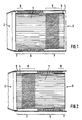
- a honeycomb body arrangement comprising a cylindrical or oval honeycomb body 1, in particular as a catalyst carrier body for motor vehicles with a catalytic Active coating formed with a fluid inlet side 2 and Fluid outlet side 3, constructed from at least partially structured sheet metal layers after their layering and / or winding for a fluid to flow through channels form, the honeycomb body 1 of an inner jacket tube 4 and a outer jacket tube 5 arranged concentrically thereto is surrounded.
- a smooth portion 7 which is a corrugated Subarea 6 and another smooth subarea 7 follow.
- the first smooth Subarea 7 has a length of approximately 5 mm and is therefore significantly shorter than the next section.
- the corrugated one arranged predominantly on the fluid inlet side Partial area 6 is on the fluid inlet side 2 axially-partially 8 over a length of z.
- Fig. 2 shows, partly in longitudinal axial section, a second embodiment of a Honeycomb body arrangement with a cylindrical or oval honeycomb body 1.
- An the fluid inlet side 2 is first arranged a smooth portion 7, the corrugated Subarea 6 and another smooth subarea 7 follow.
- the first smooth In contrast to the honeycomb body arrangement according to FIG. 1, partial area 7 is clear longer than the second one, which is only about 5 mm long.
- the Corrugated partial area 6, which is predominantly arranged on the fluid outlet side 3, is on the fluid outlet side axially-partially 8 over a length of 3 hose corrugations with the outer jacket tube 5 soldered; the honeycomb body 1 is axially partial on the fluid inlet side 2 9 over a length of z.
- honeycomb body arrangement with a honeycomb body 1 usual length of about 100 to 150 mm supports due to the fluid inlet side longer first, thermally insulated from the outer jacket tube 5, smooth Partial area 7 particularly well a quick response of the catalyst carrier body when applying exhaust gas from an engine in the cold start phase.
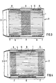
- Fig. 3 shows, partly in section, a third embodiment of a honeycomb body arrangement with a honeycomb body 1.
- a smooth section 7 is arranged, which is a corrugated section 6 second smooth section 7, a second corrugated section 6 and finally a follow third smooth section 6.
- the fluid inlet and outlet sides are smooth Subregions 7 each have a length of approximately 5 mm and are therefore significantly shorter than the middle, axially-centrally arranged smooth section 7.
- the Honeycomb body 1 is partially axial 9 over a length of 25 mm with the long, axially central arranged sparse portion 7 soldered; the fluid inlet and fluid outlet side arranged corrugated sections 6 are axially partially 8 each over a length of z. B.
- the corrugated partial areas 6 are particularly good mechanical loads, in particular for honeycomb body 1 with a higher Overall length of more than 150 mm.
- Fig. 4 shows, partly in longitudinal axial section, a fourth embodiment of a Honeycomb body arrangement with a cylindrical honeycomb body 1.
- a smooth partial area 7 is arranged, which has a corrugated partial area 6 and another smooth section 7 follow.
- the fluid entry and Fluid outlet side smooth partial areas 7 are significantly longer than the corresponding ones smooth partial areas 7 according to FIG. 3.
- the honeycomb body 1 is fluid entry and fluid outlet side axially partially 9 each over a length of z. B. 15 mm with the sponges 7 soldered; the axially-centrally arranged corrugated section 6 is axially-partially 8 over a length of z. B. three hose corrugations with the outer jacket tube 5 soldered.
- Such a honeycomb body arrangement with a Honeycomb body 1 also has a greater overall length of over 150 mm, on the one hand because of of the axially-centrally arranged corrugated section 6 is particularly good mechanical Loads and supports on the other hand due to the fluid inlet side longer first, thermally insulated, smooth partial area 7 an immediate restart of the catalyst carrier body.
- FIG. 5 shows, partly in section, an embodiment of a honeycomb body arrangement as in Fig. 4, but for a conical honeycomb body.
- conical honeycomb body 1 allows under Maintaining the advantages of the invention shown construction relatively compact emission control systems with very good flow distributions and particularly good cold start behavior.
- the hose corrugations have of the corrugated sections 6 viewed over their longitudinal axial section flank areas great steepness, in particular even an omega shape.
- Figures 6 and 7 show sections of alternative hose corrugations with flattened, in particular trapezoidal, flank areas which are in the axially partial 8th Area of soldering to the outer jacket tube 5 the advantage of a more permanent connection than with omega-shaped Have hose corrugations.
- the present invention enables safe manufacturing of honeycomb structures that can withstand particularly high loads can and a good cold start behavior in the exhaust gas purification system Show motor vehicle.
Landscapes
- Chemical & Material Sciences (AREA)
- Chemical Kinetics & Catalysis (AREA)
- Engineering & Computer Science (AREA)
- Health & Medical Sciences (AREA)
- Toxicology (AREA)
- Combustion & Propulsion (AREA)
- Mechanical Engineering (AREA)
- General Engineering & Computer Science (AREA)
- Exhaust Gas After Treatment (AREA)
- Catalysts (AREA)
Applications Claiming Priority (3)
| Application Number | Priority Date | Filing Date | Title |
|---|---|---|---|
| DE19825230A DE19825230A1 (de) | 1998-06-05 | 1998-06-05 | Wabenkörperanordnung |
| DE19825230 | 1998-06-05 | ||
| PCT/EP1999/003711 WO1999064731A1 (de) | 1998-06-05 | 1999-05-28 | Wabenkörperanordnung |
Publications (2)
| Publication Number | Publication Date |
|---|---|
| EP1084333A1 EP1084333A1 (de) | 2001-03-21 |
| EP1084333B1 true EP1084333B1 (de) | 2002-04-24 |
Family
ID=7870063
Family Applications (1)
| Application Number | Title | Priority Date | Filing Date |
|---|---|---|---|
| EP99927789A Expired - Lifetime EP1084333B1 (de) | 1998-06-05 | 1999-05-28 | Wabenkörperanordnung |
Country Status (7)
| Country | Link |
|---|---|
| US (1) | US6368726B1 (enExample) |
| EP (1) | EP1084333B1 (enExample) |
| JP (1) | JP2002517670A (enExample) |
| CN (1) | CN1122753C (enExample) |
| DE (2) | DE19825230A1 (enExample) |
| ES (1) | ES2177287T3 (enExample) |
| WO (1) | WO1999064731A1 (enExample) |
Families Citing this family (26)
| Publication number | Priority date | Publication date | Assignee | Title |
|---|---|---|---|---|
| DE19819202A1 (de) * | 1998-04-29 | 1999-11-04 | Emitec Emissionstechnologie | Konischer Wabenkörper und Verfahren zu seiner Herstellung |
| US6938339B2 (en) * | 2000-12-19 | 2005-09-06 | Corning Incorporated | Method and apparatus for forming an inlet and outlet face of a catalyst support |
| DE10137878A1 (de) * | 2001-08-02 | 2003-02-27 | Emitec Emissionstechnologie | Abgaskatalysator mit Dehnungen ausgleichender Lagerung |
| US6660401B2 (en) * | 2001-12-20 | 2003-12-09 | Charles Hsu | Disposition of solder for heat resistant structure |
| JP2003200060A (ja) * | 2002-01-10 | 2003-07-15 | Calsonic Kansei Corp | 金属製触媒担体およびその製造方法 |
| DE10217259A1 (de) * | 2002-04-18 | 2003-11-13 | Emitec Emissionstechnologie | Katalysator-Trägerkörper mit Wellmantel und Verfahren zu dessen Herstellung |
| US7404254B2 (en) * | 2002-04-18 | 2008-07-29 | Emitec Gesellschaft Fuer Emissions Technologie Mbh | Calibrated catalyst carrier body with corrugated casing and method for manufacturing the same |
| DE102005045015A1 (de) * | 2005-09-21 | 2007-03-29 | Robert Bosch Gmbh | Filterelement und Rußfilter mit verbesserter Thermoschockbeständigkeit |
| DE102005045492A1 (de) * | 2005-09-23 | 2007-03-29 | Emitec Gesellschaft Für Emissionstechnologie Mbh | Wabenkörper mit stirnseitiger Hartlot-Zone |
| US20110039461A1 (en) * | 2005-12-12 | 2011-02-17 | Brunswick Corporation | Exhaust plenum for distributing exhaust gas uniformly through a catalyst module |
| US20100130079A1 (en) * | 2005-12-12 | 2010-05-27 | Brunswick Corporation | Marine engine exhaust system having a plurality of catalyst devices disposed in parallel with each other |
| US20100087109A1 (en) * | 2005-12-12 | 2010-04-08 | Brunswick Corporation | Marine engine with thermally insulated catalyst structures |
| US20100112878A1 (en) * | 2005-12-12 | 2010-05-06 | Brunswick Corporation | Catalyst device for a marine engine which is generally tubular with a rim portion |
| US7698889B1 (en) | 2005-12-12 | 2010-04-20 | Brunswick Corporation | Porous insert for an exhaust system of a marine engine |
| US7552586B1 (en) | 2005-12-12 | 2009-06-30 | Brunswick Corporation | Marine exhaust system with a downstream oxygen sensor located away from a water reversion liquid trajectory path |
| US20100087108A1 (en) * | 2005-12-12 | 2010-04-08 | Brunswick Corporation | Concentricity spacer for a catalyst device of a marine engine |
| US20070243116A1 (en) * | 2006-04-13 | 2007-10-18 | Klaus Mueller-Haas | Metallic substrate system |
| US7611561B2 (en) * | 2006-07-20 | 2009-11-03 | Benteler Automotive Corporation | Diesel exhaust filter construction |
| JP5028298B2 (ja) * | 2008-02-25 | 2012-09-19 | ヤマハ発動機株式会社 | 船外機 |
| US8598073B2 (en) | 2009-04-20 | 2013-12-03 | Corning Incorporated | Methods of making and using activated carbon-containing coated substrates and the products made therefrom |
| JP2013160202A (ja) * | 2012-02-08 | 2013-08-19 | Yamaha Motor Co Ltd | 船舶推進装置 |
| DE112014001018T5 (de) * | 2013-02-27 | 2015-12-03 | Cummins Emission Solutions Inc. | Herstellungsartikel zur Sicherung eines Katalysator-Substrats |
| DE102017207151A1 (de) * | 2017-04-27 | 2018-10-31 | Continental Automotive Gmbh | Metallischer Wabenkörper mit haftungsverbessernden Mikrostrukturen |
| CN111380213A (zh) * | 2020-03-19 | 2020-07-07 | 舒贤南 | 导热油循环加热装置以及采用该装置的精酿啤酒酿造设备 |
| DE102021211212A1 (de) | 2021-10-05 | 2023-04-06 | Vitesco Technologies GmbH | Vorrichtung zur Abgasnachbehandlung mit einer Schweißverbindung zwischen Trägerrohr und Wellmantel |
| DE102022212757A1 (de) * | 2022-11-29 | 2024-05-29 | Emitec Technologies GmbH | Vorrichtung zur Nachbehandlung von Abgasen |
Family Cites Families (22)
| Publication number | Priority date | Publication date | Assignee | Title |
|---|---|---|---|---|
| DE292784C (enExample) * | ||||
| DE2257968C3 (de) * | 1972-11-27 | 1980-11-13 | Degussa Ag, 6000 Frankfurt | Vorrichtung zur Reinigung der Abgase von Dieselmotoren |
| DE2300704A1 (de) * | 1973-01-08 | 1974-07-11 | Eberspaecher J | Anordnung zur katalytischen reinigung der abgase von brennkraftmaschinen |
| ATE44582T1 (de) * | 1985-07-25 | 1989-07-15 | Interatom | Halterung fuer einen metallischen abgaskatalysatortraegerkoerper und verfahren zur herstellung. |
| JPH0621558B2 (ja) * | 1986-08-25 | 1994-03-23 | カルソニック株式会社 | メタルハニカム担体 |
| DE3634235C1 (de) * | 1986-10-08 | 1988-03-31 | Sueddeutsche Kuehler Behr | Matrix fuer einen katalytischen Reaktor zur Abgasreinigung |
| JPH0192238U (enExample) * | 1987-12-07 | 1989-06-16 | ||
| KR920005089B1 (ko) * | 1988-07-06 | 1992-06-26 | 우스이 고꾸사이 산교 가부시끼가이샤 | 배기가스 정화용 촉매를 담지하기 위한 금속제 담지모체(擔持母體)와 그의 제조방법 |
| KR920009120B1 (ko) * | 1988-07-06 | 1992-10-13 | 우스이 고꾸사이 산교 가부시끼가이샤 | 배기가스 정화용 촉매를 담지하기 위한 금속제 담지모체(擔持母體) |
| JPH0616855B2 (ja) * | 1988-07-22 | 1994-03-09 | 日本冶金工業株式会社 | 触媒反応器のための担持母体 |
| DE3837503A1 (de) * | 1988-11-04 | 1990-05-10 | Gillet Heinrich Gmbh | Abgas-katalysator fuer kraftfahrzeuge |
| US5346675A (en) * | 1988-12-16 | 1994-09-13 | Usui Kokusai Sangyo Kabushiki Kaisha | Exhaust gas cleaning apparatus |
| JPH0619794Y2 (ja) * | 1988-12-16 | 1994-05-25 | 臼井国際産業株式会社 | 排気ガス浄化装置 |
| DE3926072C2 (de) * | 1989-08-07 | 1994-01-13 | Emitec Emissionstechnologie | Katalysator zur Abgasreinigung mit elastischen Elementen zum Ausgleich von Längsdehnungen |
| JP2553733B2 (ja) * | 1990-04-17 | 1996-11-13 | 昭和飛行機工業株式会社 | 耐熱構造体 |
| JP2832397B2 (ja) * | 1990-12-26 | 1998-12-09 | トヨタ自動車株式会社 | 排気ガス浄化触媒用メタル担体 |
| JPH04235717A (ja) * | 1991-01-16 | 1992-08-24 | Toyota Motor Corp | 排気ガス浄化触媒用メタル担体 |
| JP2819864B2 (ja) * | 1991-06-26 | 1998-11-05 | トヨタ自動車株式会社 | 排気ガス浄化触媒用メタル担体 |
| DE4303950C1 (de) * | 1993-02-10 | 1994-10-06 | Emitec Emissionstechnologie | In einem inneren und einem äußeren Mantelrohr gehalterter metallischer Wabenkörper, insbesondere Katalysator-Trägerkörper |
| JPH07174019A (ja) * | 1993-12-20 | 1995-07-11 | Calsonic Corp | 金属触媒コンバータ |
| US5916530A (en) * | 1994-08-29 | 1999-06-29 | Emitec Gesellschaft Fuer Emissionstechnologie Mbh | Catalytic reactor |
| JPH10235205A (ja) * | 1997-02-26 | 1998-09-08 | Nippon Steel Corp | 金属製触媒コンバータおよびその製造方法 |
-
1998
- 1998-06-05 DE DE19825230A patent/DE19825230A1/de not_active Withdrawn
-
1999
- 1999-05-28 EP EP99927789A patent/EP1084333B1/de not_active Expired - Lifetime
- 1999-05-28 DE DE59901307T patent/DE59901307D1/de not_active Expired - Fee Related
- 1999-05-28 ES ES99927789T patent/ES2177287T3/es not_active Expired - Lifetime
- 1999-05-28 WO PCT/EP1999/003711 patent/WO1999064731A1/de not_active Ceased
- 1999-05-28 CN CN99807055A patent/CN1122753C/zh not_active Expired - Fee Related
- 1999-05-28 JP JP2000553709A patent/JP2002517670A/ja active Pending
-
2000
- 2000-12-05 US US09/730,267 patent/US6368726B1/en not_active Expired - Fee Related
Also Published As
| Publication number | Publication date |
|---|---|
| EP1084333A1 (de) | 2001-03-21 |
| JP2002517670A (ja) | 2002-06-18 |
| WO1999064731A1 (de) | 1999-12-16 |
| CN1122753C (zh) | 2003-10-01 |
| US6368726B1 (en) | 2002-04-09 |
| DE19825230A1 (de) | 1999-12-09 |
| DE59901307D1 (de) | 2002-05-29 |
| CN1304477A (zh) | 2001-07-18 |
| ES2177287T3 (es) | 2002-12-01 |
Similar Documents
| Publication | Publication Date | Title |
|---|---|---|
| EP1084333B1 (de) | Wabenkörperanordnung | |
| EP0683851B1 (de) | In einem inneren und einem äusseren mantelrohr gehalterter metallischer wabenkörper, insbesondere katalysator-trägerkörper | |
| EP0673473B1 (de) | Katalytischer konverter mit zwei oder mehr wabenkörpern in einem mantelrohr und verfahren zu seiner herstellung | |
| DE19722603C1 (de) | Leitungselement mit wenigstens zwei Bälgen und einem diese verbindenden Zwischenrohr | |
| EP1009924B1 (de) | Katalysatorträgeranordnung für einen motornahen einbau | |
| EP0929738B1 (de) | Wabenkörper mit wärmeisolierung, vorzugsweise für einen abgaskatalysator | |
| EP1830042A2 (de) | Statischer Mischer und Abgasbehandlungseinrichtung | |
| EP0220468A1 (de) | Aus Blechen gewickelter oder geschichteter metallischer Katalysatorträgerkörper mit Doppel- oder Mehrfachwellenstruktur | |
| EP1206631A1 (de) | Abgaskrümmer | |
| DE69301107T2 (de) | Vorrichtung zur Reinigung von Abgasen | |
| EP0846030B9 (de) | Verfahren zum herstellen eines wabenkörpers aus zumindest zum teil schichtartig aufgebauten metallblechlagen | |
| WO2011036245A1 (de) | Streckbarer wickelschlauch | |
| WO1996027735A1 (de) | Metallischer wabenkörper | |
| DE2400443A1 (de) | Vorrichtung zum reinigen der abgase von brennkraftmaschinen | |
| EP0983425A1 (de) | Wabenkörper mit einem system zur vermeidung mechanischer schwingungen | |
| EP0812246A1 (de) | Wabenkörper mit nur teilweiser anbindung an ein mantelrohr | |
| WO2001079670A1 (de) | Katalysator-trägrkörper mit manschette und verkürztem mantelrohr | |
| EP0969929B1 (de) | Wabenkörper, insbesondere katalysator-trägerkörper, mit verstärkter wandstruktur | |
| WO2001053668A1 (de) | Katalysator-trägerkörper mit einer dehnungen erlaubenden manschette mit mikrostrukturen | |
| DE102010037772A1 (de) | Fixierter Wickelschlauch | |
| EP3591183B1 (de) | Flexibles leitungselement für die abgasanlage eines verbrennungsmotors | |
| DE102018214929B4 (de) | Katalysator mit metallischem Wabenkörper | |
| DE19755703A1 (de) | Katalysatorträgeranordnung für einen motornahen Einbau | |
| WO1999005403A1 (de) | Halterung eines trägerkörpers in einem mantelrohr | |
| EP1859132A1 (de) | Gehäuse für eine abgasbehandlungskomponente mit verstärkungshülse |
Legal Events
| Date | Code | Title | Description |
|---|---|---|---|
| PUAI | Public reference made under article 153(3) epc to a published international application that has entered the european phase |
Free format text: ORIGINAL CODE: 0009012 |
|
| 17P | Request for examination filed |
Effective date: 20001114 |
|
| AK | Designated contracting states |
Kind code of ref document: A1 Designated state(s): DE ES FR GB IT |
|
| GRAG | Despatch of communication of intention to grant |
Free format text: ORIGINAL CODE: EPIDOS AGRA |
|
| 17Q | First examination report despatched |
Effective date: 20010615 |
|
| GRAG | Despatch of communication of intention to grant |
Free format text: ORIGINAL CODE: EPIDOS AGRA |
|
| GRAH | Despatch of communication of intention to grant a patent |
Free format text: ORIGINAL CODE: EPIDOS IGRA |
|
| REG | Reference to a national code |
Ref country code: GB Ref legal event code: IF02 |
|
| GRAH | Despatch of communication of intention to grant a patent |
Free format text: ORIGINAL CODE: EPIDOS IGRA |
|
| GRAA | (expected) grant |
Free format text: ORIGINAL CODE: 0009210 |
|
| AK | Designated contracting states |
Kind code of ref document: B1 Designated state(s): DE ES FR GB IT |
|
| REG | Reference to a national code |
Ref country code: GB Ref legal event code: FG4D Free format text: NOT ENGLISH |
|
| REF | Corresponds to: |
Ref document number: 59901307 Country of ref document: DE Date of ref document: 20020529 |
|
| GBT | Gb: translation of ep patent filed (gb section 77(6)(a)/1977) |
Effective date: 20020724 |
|
| ET | Fr: translation filed | ||
| REG | Reference to a national code |
Ref country code: ES Ref legal event code: FG2A Ref document number: 2177287 Country of ref document: ES Kind code of ref document: T3 |
|
| PLBE | No opposition filed within time limit |
Free format text: ORIGINAL CODE: 0009261 |
|
| STAA | Information on the status of an ep patent application or granted ep patent |
Free format text: STATUS: NO OPPOSITION FILED WITHIN TIME LIMIT |
|
| 26N | No opposition filed |
Effective date: 20030127 |
|
| PGFP | Annual fee paid to national office [announced via postgrant information from national office to epo] |
Ref country code: ES Payment date: 20080522 Year of fee payment: 10 Ref country code: DE Payment date: 20080523 Year of fee payment: 10 |
|
| PGFP | Annual fee paid to national office [announced via postgrant information from national office to epo] |
Ref country code: IT Payment date: 20080520 Year of fee payment: 10 |
|
| PGFP | Annual fee paid to national office [announced via postgrant information from national office to epo] |
Ref country code: FR Payment date: 20080521 Year of fee payment: 10 |
|
| PGFP | Annual fee paid to national office [announced via postgrant information from national office to epo] |
Ref country code: GB Payment date: 20080520 Year of fee payment: 10 |
|
| GBPC | Gb: european patent ceased through non-payment of renewal fee |
Effective date: 20090528 |
|
| REG | Reference to a national code |
Ref country code: FR Ref legal event code: ST Effective date: 20100129 |
|
| PG25 | Lapsed in a contracting state [announced via postgrant information from national office to epo] |
Ref country code: FR Free format text: LAPSE BECAUSE OF NON-PAYMENT OF DUE FEES Effective date: 20090602 |
|
| PG25 | Lapsed in a contracting state [announced via postgrant information from national office to epo] |
Ref country code: GB Free format text: LAPSE BECAUSE OF NON-PAYMENT OF DUE FEES Effective date: 20090528 |
|
| PG25 | Lapsed in a contracting state [announced via postgrant information from national office to epo] |
Ref country code: DE Free format text: LAPSE BECAUSE OF NON-PAYMENT OF DUE FEES Effective date: 20091201 |
|
| REG | Reference to a national code |
Ref country code: ES Ref legal event code: FD2A Effective date: 20090529 |
|
| PG25 | Lapsed in a contracting state [announced via postgrant information from national office to epo] |
Ref country code: ES Free format text: LAPSE BECAUSE OF NON-PAYMENT OF DUE FEES Effective date: 20090529 |
|
| PG25 | Lapsed in a contracting state [announced via postgrant information from national office to epo] |
Ref country code: IT Free format text: LAPSE BECAUSE OF NON-PAYMENT OF DUE FEES Effective date: 20090528 |