EP1084333B1 - Honeycomb arrangement - Google Patents
Honeycomb arrangement Download PDFInfo
- Publication number
- EP1084333B1 EP1084333B1 EP99927789A EP99927789A EP1084333B1 EP 1084333 B1 EP1084333 B1 EP 1084333B1 EP 99927789 A EP99927789 A EP 99927789A EP 99927789 A EP99927789 A EP 99927789A EP 1084333 B1 EP1084333 B1 EP 1084333B1
- Authority
- EP
- European Patent Office
- Prior art keywords
- honeycomb body
- arrangement according
- corrugated
- corrugated portion
- axially
- Prior art date
- Legal status (The legal status is an assumption and is not a legal conclusion. Google has not performed a legal analysis and makes no representation as to the accuracy of the status listed.)
- Expired - Lifetime
Links
Images

Classifications
-
- F—MECHANICAL ENGINEERING; LIGHTING; HEATING; WEAPONS; BLASTING
- F01—MACHINES OR ENGINES IN GENERAL; ENGINE PLANTS IN GENERAL; STEAM ENGINES
- F01N—GAS-FLOW SILENCERS OR EXHAUST APPARATUS FOR MACHINES OR ENGINES IN GENERAL; GAS-FLOW SILENCERS OR EXHAUST APPARATUS FOR INTERNAL COMBUSTION ENGINES
- F01N3/00—Exhaust or silencing apparatus having means for purifying, rendering innocuous, or otherwise treating exhaust
- F01N3/08—Exhaust or silencing apparatus having means for purifying, rendering innocuous, or otherwise treating exhaust for rendering innocuous
- F01N3/10—Exhaust or silencing apparatus having means for purifying, rendering innocuous, or otherwise treating exhaust for rendering innocuous by thermal or catalytic conversion of noxious components of exhaust
- F01N3/24—Exhaust or silencing apparatus having means for purifying, rendering innocuous, or otherwise treating exhaust for rendering innocuous by thermal or catalytic conversion of noxious components of exhaust characterised by constructional aspects of converting apparatus
- F01N3/28—Construction of catalytic reactors
- F01N3/2839—Arrangements for mounting catalyst support in housing, e.g. with means for compensating thermal expansion or vibration
- F01N3/2875—Arrangements for mounting catalyst support in housing, e.g. with means for compensating thermal expansion or vibration by using elastic means, e.g. spring leaves, for retaining catalyst body in the housing
-
- F—MECHANICAL ENGINEERING; LIGHTING; HEATING; WEAPONS; BLASTING
- F01—MACHINES OR ENGINES IN GENERAL; ENGINE PLANTS IN GENERAL; STEAM ENGINES
- F01N—GAS-FLOW SILENCERS OR EXHAUST APPARATUS FOR MACHINES OR ENGINES IN GENERAL; GAS-FLOW SILENCERS OR EXHAUST APPARATUS FOR INTERNAL COMBUSTION ENGINES
- F01N2330/00—Structure of catalyst support or particle filter
- F01N2330/02—Metallic plates or honeycombs, e.g. superposed or rolled-up corrugated or otherwise deformed sheet metal
-
- Y—GENERAL TAGGING OF NEW TECHNOLOGICAL DEVELOPMENTS; GENERAL TAGGING OF CROSS-SECTIONAL TECHNOLOGIES SPANNING OVER SEVERAL SECTIONS OF THE IPC; TECHNICAL SUBJECTS COVERED BY FORMER USPC CROSS-REFERENCE ART COLLECTIONS [XRACs] AND DIGESTS
- Y02—TECHNOLOGIES OR APPLICATIONS FOR MITIGATION OR ADAPTATION AGAINST CLIMATE CHANGE
- Y02A—TECHNOLOGIES FOR ADAPTATION TO CLIMATE CHANGE
- Y02A50/00—TECHNOLOGIES FOR ADAPTATION TO CLIMATE CHANGE in human health protection, e.g. against extreme weather
- Y02A50/20—Air quality improvement or preservation, e.g. vehicle emission control or emission reduction by using catalytic converters
-
- Y—GENERAL TAGGING OF NEW TECHNOLOGICAL DEVELOPMENTS; GENERAL TAGGING OF CROSS-SECTIONAL TECHNOLOGIES SPANNING OVER SEVERAL SECTIONS OF THE IPC; TECHNICAL SUBJECTS COVERED BY FORMER USPC CROSS-REFERENCE ART COLLECTIONS [XRACs] AND DIGESTS
- Y10—TECHNICAL SUBJECTS COVERED BY FORMER USPC
- Y10T—TECHNICAL SUBJECTS COVERED BY FORMER US CLASSIFICATION
- Y10T29/00—Metal working
- Y10T29/49—Method of mechanical manufacture
- Y10T29/49345—Catalytic device making
-
- Y—GENERAL TAGGING OF NEW TECHNOLOGICAL DEVELOPMENTS; GENERAL TAGGING OF CROSS-SECTIONAL TECHNOLOGIES SPANNING OVER SEVERAL SECTIONS OF THE IPC; TECHNICAL SUBJECTS COVERED BY FORMER USPC CROSS-REFERENCE ART COLLECTIONS [XRACs] AND DIGESTS
- Y10—TECHNICAL SUBJECTS COVERED BY FORMER USPC
- Y10T—TECHNICAL SUBJECTS COVERED BY FORMER US CLASSIFICATION
- Y10T428/00—Stock material or miscellaneous articles
- Y10T428/12—All metal or with adjacent metals
- Y10T428/1234—Honeycomb, or with grain orientation or elongated elements in defined angular relationship in respective components [e.g., parallel, inter- secting, etc.]
-
- Y—GENERAL TAGGING OF NEW TECHNOLOGICAL DEVELOPMENTS; GENERAL TAGGING OF CROSS-SECTIONAL TECHNOLOGIES SPANNING OVER SEVERAL SECTIONS OF THE IPC; TECHNICAL SUBJECTS COVERED BY FORMER USPC CROSS-REFERENCE ART COLLECTIONS [XRACs] AND DIGESTS
- Y10—TECHNICAL SUBJECTS COVERED BY FORMER USPC
- Y10T—TECHNICAL SUBJECTS COVERED BY FORMER US CLASSIFICATION
- Y10T428/00—Stock material or miscellaneous articles
- Y10T428/12—All metal or with adjacent metals
- Y10T428/1241—Nonplanar uniform thickness or nonlinear uniform diameter [e.g., L-shape]
Definitions
- the invention relates to a honeycomb body arrangement
- a honeycomb body arrangement comprising a honeycomb body with a fluid inlet side and a fluid outlet side, in particular catalyst carrier body for motor vehicles, from at least partially structured sheet metal layers, the channels through which a fluid can flow after their layering and / or winding form, the honeycomb body of an inner jacket tube and a concentrically arranged outer jacket tube is surrounded and wherein inner jacket tube at least in an axial section as a corrugated hose is trained.
- honeycomb body arrangements are known per se. DE 2 300 704 z.
- elastic Holding elements are arranged in particular corrugated tube sections, which thermally induced relative movements between the honeycomb body and the should accommodate the outer jacket tube.
- the elastic elements are either in two parts, each on the fluid inlet and fluid outlet side, or in one part, via the total length of the honeycomb body, arranged and each have a flange for connection to a pipeline.
- the invention is based, a reproducible with constant the task Specify quality manufacturable honeycomb body arrangement by a good Balancing mechanical and thermal loads a permanent and safe Storage of a honeycomb body made of sheet metal layers in a metallic Housing guaranteed even under special operating loads.
- An additional The task is also a good cold start behavior of the catalytic exhaust gas purification device to achieve.
- the honeycomb body arrangement is preferably characterized in that that a smooth portion is first arranged on the fluid inlet side, the at least one corrugated section and at least one further smooth section follow, so that a total of n corrugated sections and n + 1 smooth sections are arranged, where n is an integer and greater than or equal to 1.
- a smooth portion is first arranged on the fluid inlet side, the at least one corrugated section and at least one further smooth section follow, so that a total of n corrugated sections and n + 1 smooth sections are arranged, where n is an integer and greater than or equal to 1.
- the Fluid inlet side arrangement of a smooth acting as air gap insulation Partial area is advantageously a quick start of the catalytic Reaction guaranteed at the beginning of the exposure to the exhaust gas to be cleaned.
- the thermal insulation can also be provided by a Insulating mat, for example made of ceramic material, which is very low Has heat conduction and heat convection properties can be improved.
- n 1
- the one corrugated partial area mainly arranged on the fluid inlet side.
- n 1
- the one corrugated section can also predominate be arranged on the fluid outlet side, in particular when a long, smooth first Partial area to achieve a large, insulated from the outer jacket tube Volume in the honeycomb body is desired.
- the corrugated section is on the fluid inlet side behind a smooth one Partial area and another corrugated partial area on the fluid outlet side in front of one smooth portion arranged.
- the first corrugated section is on the fluid inlet side, the second corrugated Axial-central section and the third corrugated section on the fluid outlet side arranged, alternating with smooth sections.
- Such an arrangement combines the advantages already shown in extremely stressed areas, for example Honeycomb structures installed close to the motor.
- the corrugated and smooth sub-areas arranged analogous to the previous versions.
- the inner jacket tube must be at least in one Area connected to the honeycomb body and in one area with the outer jacket tube. All smooth partial areas are preferred, at least partially connected to the honeycomb body, in particular brazed. Also be preferably all corrugated sections are connected to the outer casing tube, preferably also brazed or welded. But it is important, not all To connect wave crests with the outer casing tube, otherwise the effect the corrugations would be hindered as a compensator for stretching. At least one Part of the wave crests should remain without connections, especially should not two on both sides to a smooth section of the inner jacket tube adjacent wave crests must be connected to the outer casing tube.
- the sum of the axial lengths is corrugated sections more than half, preferably more than two thirds of the Total length of the honeycomb body. This is advantageous in particular balancing mechanical loads is easier.
- the hose corrugations have the corrugated Partial areas across their longitudinal axial section consider larger flank areas Steepness, in particular even an omega shape.
- hose corrugations ensure a load-adjusted one Expand and shrink the inner jacket tube.
- the hose corrugations are preferably independent of their remaining shape in the Flattened area of their technical connection with the outer jacket tube educated. Such flattened areas allow a flat, high Connection that withstands mechanical and thermal loads.
- the partial connection between a corrugated section and the outer jacket tube therefore extends over 1 to 5, preferably over 2 to 4, in particular over 3, wave crests of the hose corrugation of the corrugated Subarea so that the connections are permanent and according to their use are technically safe to manufacture.
- the ratio is preferably more technically connected Hose corrugations for hose corrugations that are not technically connected at most 1: 1.5, preferably 1: 4, so that a compensation in particular mechanical loads is guaranteed.
- the first smooth partial area arranged on the fluid inlet side is at least 5 mm long, preferably at least 7.5 mm, in particular about 10 mm, the others smooth sections are at least 15 mm long, preferably at least 20 mm, especially about 25 mm.
- honeycomb body which in particular is an axially flowable catalyst carrier body is any geometric, preferably a cylindrical or conical, shape.
- a honeycomb body arrangement comprising a cylindrical or oval honeycomb body 1, in particular as a catalyst carrier body for motor vehicles with a catalytic Active coating formed with a fluid inlet side 2 and Fluid outlet side 3, constructed from at least partially structured sheet metal layers after their layering and / or winding for a fluid to flow through channels form, the honeycomb body 1 of an inner jacket tube 4 and a outer jacket tube 5 arranged concentrically thereto is surrounded.
- a smooth portion 7 which is a corrugated Subarea 6 and another smooth subarea 7 follow.
- the first smooth Subarea 7 has a length of approximately 5 mm and is therefore significantly shorter than the next section.
- the corrugated one arranged predominantly on the fluid inlet side Partial area 6 is on the fluid inlet side 2 axially-partially 8 over a length of z.
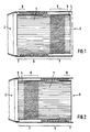
- Fig. 2 shows, partly in longitudinal axial section, a second embodiment of a Honeycomb body arrangement with a cylindrical or oval honeycomb body 1.
- An the fluid inlet side 2 is first arranged a smooth portion 7, the corrugated Subarea 6 and another smooth subarea 7 follow.
- the first smooth In contrast to the honeycomb body arrangement according to FIG. 1, partial area 7 is clear longer than the second one, which is only about 5 mm long.
- the Corrugated partial area 6, which is predominantly arranged on the fluid outlet side 3, is on the fluid outlet side axially-partially 8 over a length of 3 hose corrugations with the outer jacket tube 5 soldered; the honeycomb body 1 is axially partial on the fluid inlet side 2 9 over a length of z.
- honeycomb body arrangement with a honeycomb body 1 usual length of about 100 to 150 mm supports due to the fluid inlet side longer first, thermally insulated from the outer jacket tube 5, smooth Partial area 7 particularly well a quick response of the catalyst carrier body when applying exhaust gas from an engine in the cold start phase.
- Fig. 3 shows, partly in section, a third embodiment of a honeycomb body arrangement with a honeycomb body 1.
- a smooth section 7 is arranged, which is a corrugated section 6 second smooth section 7, a second corrugated section 6 and finally a follow third smooth section 6.
- the fluid inlet and outlet sides are smooth Subregions 7 each have a length of approximately 5 mm and are therefore significantly shorter than the middle, axially-centrally arranged smooth section 7.
- the Honeycomb body 1 is partially axial 9 over a length of 25 mm with the long, axially central arranged sparse portion 7 soldered; the fluid inlet and fluid outlet side arranged corrugated sections 6 are axially partially 8 each over a length of z. B.
- the corrugated partial areas 6 are particularly good mechanical loads, in particular for honeycomb body 1 with a higher Overall length of more than 150 mm.
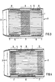
- Fig. 4 shows, partly in longitudinal axial section, a fourth embodiment of a Honeycomb body arrangement with a cylindrical honeycomb body 1.
- a smooth partial area 7 is arranged, which has a corrugated partial area 6 and another smooth section 7 follow.
- the fluid entry and Fluid outlet side smooth partial areas 7 are significantly longer than the corresponding ones smooth partial areas 7 according to FIG. 3.
- the honeycomb body 1 is fluid entry and fluid outlet side axially partially 9 each over a length of z. B. 15 mm with the sponges 7 soldered; the axially-centrally arranged corrugated section 6 is axially-partially 8 over a length of z. B. three hose corrugations with the outer jacket tube 5 soldered.
- Such a honeycomb body arrangement with a Honeycomb body 1 also has a greater overall length of over 150 mm, on the one hand because of of the axially-centrally arranged corrugated section 6 is particularly good mechanical Loads and supports on the other hand due to the fluid inlet side longer first, thermally insulated, smooth partial area 7 an immediate restart of the catalyst carrier body.
- FIG. 5 shows, partly in section, an embodiment of a honeycomb body arrangement as in Fig. 4, but for a conical honeycomb body.
- conical honeycomb body 1 allows under Maintaining the advantages of the invention shown construction relatively compact emission control systems with very good flow distributions and particularly good cold start behavior.
- the hose corrugations have of the corrugated sections 6 viewed over their longitudinal axial section flank areas great steepness, in particular even an omega shape.
- Figures 6 and 7 show sections of alternative hose corrugations with flattened, in particular trapezoidal, flank areas which are in the axially partial 8th Area of soldering to the outer jacket tube 5 the advantage of a more permanent connection than with omega-shaped Have hose corrugations.
- the present invention enables safe manufacturing of honeycomb structures that can withstand particularly high loads can and a good cold start behavior in the exhaust gas purification system Show motor vehicle.
Abstract
Description
Die Erfindung betrifft eine Wabenkörperanordnung umfassend einen Wabenkörper mit einer Fluideintrittsseite und einer Fluidaustrittsseite, insbesondere Katalysator-Trägerkörper für Kraftfahrzeuge, aus zumindest teilweise strukturierten Blechlagen, die nach Ihrer Schichtung und/oder Wicklung für ein Fluid durchströmbare Kanäle bilden, wobei der Wabenkörper von einem inneren Mantelrohr und einem konzentrisch dazu angeordneten äußeren Mantelrohr umgeben ist und wobei das innere Mantelrohr zumindest in einem axialen Teilbereich als Wellschlauch ausgebildet ist.The invention relates to a honeycomb body arrangement comprising a honeycomb body with a fluid inlet side and a fluid outlet side, in particular catalyst carrier body for motor vehicles, from at least partially structured sheet metal layers, the channels through which a fluid can flow after their layering and / or winding form, the honeycomb body of an inner jacket tube and a concentrically arranged outer jacket tube is surrounded and wherein inner jacket tube at least in an axial section as a corrugated hose is trained.
Solche Wabenkörperanordnungen sind an sich bekannt. In der DE 2 300 704 sind z. B. keramische Wabenkörper beschrieben, die auf ihrer Oberfläche eine metallische Schicht aufweisen. Mit dieser Schicht sind elastische Elemente verbunden, die ihrerseits wiederum in dem äußeren Mantelrohr gelagert sind. Als elastische Haltelemente sind insbesondere Wellrohrabschnitte angeordnet, welche die thermisch bedingten Relativbewegungen zwischen dem Wabenkörper und dem äußeren Mantelrohr aufnehmen sollen. Die elastischen Elemente sind entweder zweiteilig, jeweils an der Fluidseintritts- und Fluidaustrittsseite, oder einteilig, über die Gesamtlänge des Wabenkörpers, angeordnet und weisen jeweils einen Flansch zum Anschluß an eine Rohrleitung auf.Such honeycomb body arrangements are known per se. DE 2 300 704 z. B. ceramic honeycomb body described, which has a metallic on its surface Have layer. With this layer elastic elements are connected, which are in turn stored in the outer jacket tube. As elastic Holding elements are arranged in particular corrugated tube sections, which thermally induced relative movements between the honeycomb body and the should accommodate the outer jacket tube. The elastic elements are either in two parts, each on the fluid inlet and fluid outlet side, or in one part, via the total length of the honeycomb body, arranged and each have a flange for connection to a pipeline.
Auch für metallische, aus Blechlagen aufgebaute Wabenkörper, ist beispielsweise aus der DE 39 41 642 A1 zur Verhinderung von Spannungen aufgrund von thermischen Dehnungen bekannt, Blechlagen mit einem auBeren Mantelrohr aus Metall zu umgeben, welches kurze Wellen in geringem Abstand besitzt, so daß ein Wabenkörper mit einem solchen äußeren Mantelrohr expandieren und schrumpfen kann. Also for metallic honeycomb bodies made of sheet metal layers, for example from DE 39 41 642 A1 for preventing tensions due to thermal expansions known, sheet metal layers with an outer jacket tube Surround metal, which has short waves at a short distance, so that a Expand and shrink the honeycomb body with such an outer jacket tube can.
Bei Wabenkörperanardnungen mit einem inneren und einem äußeren Mantelrohr, die zumindest in Teilbereichen gegeneinander verschiebbar sein sollen, gibt es auch viele fertigungstechnische Probleme, weil insbesondere beim Löten oder Schweißen von Verbindungen jeweils sichergestellt werden muß, daß nicht unerwünschte zusätzliche Verbindungen zwischen den beiden Mantelrohren die gegenseitige Verschiebbarkeit behindern, siehe z.B. DE-A-2 300 704.In the case of honeycomb body requirements with an inner and an outer jacket tube, there are also at least parts that can be moved against each other many manufacturing problems, especially when soldering or welding of connections in each case must be ensured that not undesirable additional connections between the two jacket pipes the mutual Hinder mobility, see e.g. DE-A-2 300 704.
Der Erfindung liegt die Aufgabe zugrunde, eine reproduzierbar mit gleichbleibender Qualität herstellbare Wabenkörperanordnung anzugeben, die durch einen guten Ausgleich mechanischer und thermischer Belastungen eine dauerhafte und sichere Lagerung eines aus Blechlagen aufgebauten Wabenkörpers in einem metallischen Gehäuse auch unter besonderen Betriebsbelastungen gewährleistet. Eine zusätzliche Aufgabe ist darüber hinaus, ein gutes Kaltstartverhalten der katalytischen Abgasreinigungsvorrichtung zu errreichen.The invention is based, a reproducible with constant the task Specify quality manufacturable honeycomb body arrangement by a good Balancing mechanical and thermal loads a permanent and safe Storage of a honeycomb body made of sheet metal layers in a metallic Housing guaranteed even under special operating loads. An additional The task is also a good cold start behavior of the catalytic exhaust gas purification device to achieve.
Diese Aufgabe wird erfindungsgemäß durch eine Wabenkörperanordnung gemäß
Anspruch 1 gelöst. Vorteilhafte Ausgestaltungen und Weiterbildungen sind in den
abhängigen Ansprüchen beschrieben.According to the invention, this object is achieved by a
Indem das innere Mantelrohr des Wabenkörpers neben einem als Wellschlauch mit schlauchwellungen ausgebildeten axialen Teilbereich mindestens einen weiteren axialen Teilbereich aufweist, welcher glatt am Wabenkörper anliegt, und indem mehrere nebeneinander angeordnete Schlauwellungen des gewellten Teilbereichs und das äußere Mantelrohr axial-partiell fügetechnisch miteinander verbunden sind, und indem der glatte Teilbereich und der Wabenkörper zumindest axial-partiell fügetechnisch miteinander verbunden sind, können in vorteilhafter Weise mechanische und thermische Belastungen gleichermaßen gut ausgeglichen sowie eine dauerhafte und sichere Lagerung des Wabenkörpers im Gehäuse gewährleistet werden. ErfindungsgemäB ist jeder für eine fügetechnische Verbindung mit dem äußeren Mantelrohr vorgesehene gewellte Teilbereich in seiner partiellen Länge so bemessen, daß bekannte Verbindungsmethoden, insbesondere Lötund/oder SchweiBverfahren, leicht anwendbar sind.By placing the inner jacket tube of the honeycomb body next to a corrugated tube with tube corrugations trained axial section at least one additional axial section has, which rests smoothly on the honeycomb body, and by several sly waves arranged side by side of the corrugated section and the outer jacket tube are connected to one another in an axially partial joining technique, and by the smooth partial area and the honeycomb body at least partially axially are technically connected to each other, can advantageously mechanical and thermal loads equally balanced as well as a permanent and safe storage of the honeycomb body in the housing is guaranteed become. According to the invention, everyone is for a technical connection with its outer corrugated section provided in its partial The length is such that known connection methods, in particular soldering and / or Welding processes, are easily applicable.
Erfindungsgemäß bevorzugt zeichnet sich die Wabenkörperanordnung dadurch aus, daß an der Fluideintrittsseite zuerst ein glatter Teilbereich angeordnet ist, dem mindestens ein gewellter Teilbereich und mindestens ein weiterer glatter Teilbereich folgen, so daß insgesamt n gewellte Teilbereiche und n+1 glatte Teilbereiche angeordnet sind, wobei n ganzzahlig und größer oder gleich 1 ist. Mit der fluideintrittsseitigen Anordnung eines als Luftspaltisolierung wirkenden, glatten Teilbereichs wird in vorteilhafter Weise ein schnelles Anspringen der katalytischen Reaktion bei Beginn der Beaufschlagung mit zu reinigendem Abgas gewährleistet. Alternativ zur Luftspaltisolierung kann die thermische Isolierung auch durch eine Isoliermatte, beispielsweise aus keramischen Werkstoff, welcher sehr geringe Wärmeleit- und Wärmekonvektionseigenschaften aufweist, verbessert werden.According to the invention, the honeycomb body arrangement is preferably characterized in that that a smooth portion is first arranged on the fluid inlet side, the at least one corrugated section and at least one further smooth section follow, so that a total of n corrugated sections and n + 1 smooth sections are arranged, where n is an integer and greater than or equal to 1. With the Fluid inlet side arrangement of a smooth, acting as air gap insulation Partial area is advantageously a quick start of the catalytic Reaction guaranteed at the beginning of the exposure to the exhaust gas to be cleaned. As an alternative to the air gap insulation, the thermal insulation can also be provided by a Insulating mat, for example made of ceramic material, which is very low Has heat conduction and heat convection properties can be improved.
In einer besonderen Ausführungsform ist bei n = 1 ist der eine gewellte Teilbereich überwiegend fluideintrittsseitig angeordnet. Dadurch ist der eintrittsseitige glatte Abschnitt des inneren Mantelrohres nur kurz, z.B. 5 bis 25 mm, und es werden insbesondere die fluideintrittsseitig, durch mitunter stark pulsierendes Abgas verursachten mechanischen Belastungen in vorteilhafter Weise aufgenommen.In a special embodiment, when n = 1, the one corrugated partial area mainly arranged on the fluid inlet side. This makes the inlet side smooth Section of the inner casing tube only briefly, e.g. 5 to 25 mm, and there will be in particular on the fluid inlet side, due to the sometimes strongly pulsating exhaust gas caused mechanical loads added in an advantageous manner.
Alternativ kann in einer anderen Ausführungsform für n = 1 der eine gewellte Teilbereich axial-zentral, also in axialer Richtung gesehen im wesentlichen in der Mitte des Wabenkörpers, angeordnet sein. Dies hat den Vorteil, daß bei der Montage nicht auf die Einbaurichtung geachtet werden muß.Alternatively, in another embodiment for n = 1, the one corrugated Sub-area axially-central, that is essentially seen in the axial direction Middle of the honeycomb body. This has the advantage that the Installation does not have to take the installation direction into account.
Alternativ kann für n = 1 der eine gewellte Teilbereich auch überwiegend fluidaustrittsseitig angeordnet sein, insbesondere dann, wenn ein langer glatter erster Teilbereich zur Erzielung eines großen, vom äußeren Mantelrohr isolierten Volumens im Wabenkörper gewünscht wird.Alternatively, for n = 1, the one corrugated section can also predominate be arranged on the fluid outlet side, in particular when a long, smooth first Partial area to achieve a large, insulated from the outer jacket tube Volume in the honeycomb body is desired.
Für n = 2 sind ist gewellter Teilbereich fluideintrittsseitig hinter einem glatten Teilbereich und ein anderer gewellter Teilbereich fluidaustrittsseitig vor einem glatten Teilbereich angeordnet. Eine solche, beidseitige, also fluideintrittsseitige und fluidaustrittsseitige Lagerung des Wabenkörpers im äußeren Mantelrohr, wirkt sich besonders vorteilhaft auf den Ausgleich mechanischer Belastungen aus und bewirkt eine sehr schwingungsunempfindliche Halterung des Wabenkörpers.For n = 2, the corrugated section is on the fluid inlet side behind a smooth one Partial area and another corrugated partial area on the fluid outlet side in front of one smooth portion arranged. Such, on both sides, ie on the fluid inlet side and Storage of the honeycomb body in the outer jacket tube on the fluid outlet side has an effect particularly advantageous to balance mechanical loads and causes a very vibration-resistant bracket of the honeycomb body.
Für n = 3 sind der erste gewellte Teilbereich fluideintrittsseitig, der zweite gewellte Teilbereich axial-zentral und der dritte gewellte Teilbereich fluidaustrittsseitig angeordnet, jeweils im Wechsel mit glatten Teilbereichen. Eine solche Anordnung kombiniert die schon aufgezeigten Vorteile auch in extrem belasteten, beispielsweise motornah eingebauten Wabenkörperanordnungen. Für n größer 3 sind die gewellten und glatten Teilbereiche analog den bisherigen Ausführungen angeordnet.For n = 3, the first corrugated section is on the fluid inlet side, the second corrugated Axial-central section and the third corrugated section on the fluid outlet side arranged, alternating with smooth sections. Such an arrangement combines the advantages already shown in extremely stressed areas, for example Honeycomb structures installed close to the motor. For n greater than 3, the corrugated and smooth sub-areas arranged analogous to the previous versions.
Für eine haltbare Verbindung muß das innere Mantelrohr mindestens in einem Bereich mit dem Wabenkörper verbunden sein und in einem Bereich mit dem äußeren Mantelrohr. Bevorzugt werden alle glatten Teilbereiche zumindest partiell mit dem Wabenkörper verbunden, insbesondere hartgelötet. Außerdem werden bevorzugt alle gewellten Teilbereiche mit dem äußeren Mantelrohr verbunden, bevorzugt ebenfalls hartgelötet oder geschweißt. Dabei ist aber wichtig, nicht alle Wellenberge mit dem äußeren Mantelrohr zu verbinden, da ansonsten die Wirkung der Wellungen als Kompensator für Dehnungen behindert würde. Zumindest ein Teil der Wellenberge sollte ohne Verbindungen bleiben, insbesondere sollten nicht zwei auf beiden Seiten an einen glatten Teilbereich des inneren Mantelrohres angrenzende Wellenberge mit dem äuBeren Mantelrohr verbunden sein.For a durable connection, the inner jacket tube must be at least in one Area connected to the honeycomb body and in one area with the outer jacket tube. All smooth partial areas are preferred, at least partially connected to the honeycomb body, in particular brazed. Also be preferably all corrugated sections are connected to the outer casing tube, preferably also brazed or welded. But it is important, not all To connect wave crests with the outer casing tube, otherwise the effect the corrugations would be hindered as a compensator for stretching. At least one Part of the wave crests should remain without connections, especially should not two on both sides to a smooth section of the inner jacket tube adjacent wave crests must be connected to the outer casing tube.
In einer bevorzugten Ausführungsform beträgt Summe der Axiallängen der gewellten Teilbereiche mehr als die Hälfte, vorzugsweise mehr als zwei Drittel, der Gesamtlänge des Wabenkörpers. Dadurch wird in vorteilhafter Weise insbesondere der Ausgleich mechanischer Belastungen erleichtert.In a preferred embodiment, the sum of the axial lengths is corrugated sections more than half, preferably more than two thirds of the Total length of the honeycomb body. This is advantageous in particular balancing mechanical loads is easier.
In einer besonderen Ausführungsform weisen die Schlauchwellungen der gewellten Teilbereiche über ihren Längsaxialschnitt betrachtet Flankenbereiche großer Steilheit, insbesondere sogar eine Omegaform, auf. Eine solche Ausgestaltung der Schlauchwellungen sichert je nach thermischer Belastung ein belastungsangepaßtes Expandieren und Schrumpfen des inneren Mantelrohres. In a special embodiment, the hose corrugations have the corrugated Partial areas across their longitudinal axial section consider larger flank areas Steepness, in particular even an omega shape. Such an embodiment of the Depending on the thermal load, hose corrugations ensure a load-adjusted one Expand and shrink the inner jacket tube.
Vorzugsweise sind die Schlauchwellungen unabhängig von ihrer übrigen Form im Bereich ihrer fügetechnischen Verbindung mit dem äußeren Mantelrohr abgeflacht ausgebildet. Solche abgeflachten Bereiche ermöglichen eine flächige, hohe mechanische und thermische Belastungen aushaltende Verbindung.The hose corrugations are preferably independent of their remaining shape in the Flattened area of their technical connection with the outer jacket tube educated. Such flattened areas allow a flat, high Connection that withstands mechanical and thermal loads.
Die partielle fügetechnische Verbindung zwischen einem gewellten Teilbereich und dem äußeren Mantelrohr erstreckt sich daher jeweils über 1 bis 5, vorzugsweise über 2 bis 4, insbesondere über 3, Wellenberge der Schlauchwellung des gewellten Teilbereichs, so daß die Verbindungen ihrer Verwendung gemäß dauerhaft und fertigungstechnisch sicher herstellbar sind.The partial connection between a corrugated section and the outer jacket tube therefore extends over 1 to 5, preferably over 2 to 4, in particular over 3, wave crests of the hose corrugation of the corrugated Subarea so that the connections are permanent and according to their use are technically safe to manufacture.
ErfindungsgemäB bevorzugt beträgt das Verhältnis fügetechnisch verbundener Schlauchwellungen zu nicht fügetechnisch verbundenen Schlauchwellungen höchstens 1 : 1,5 , vorzugsweise 1 : 4, so daß ein Ausgleich insbesondere mechanischer Belastungen gewährleistet ist.According to the invention, the ratio is preferably more technically connected Hose corrugations for hose corrugations that are not technically connected at most 1: 1.5, preferably 1: 4, so that a compensation in particular mechanical loads is guaranteed.
Der an der Fluideintrittsseite angeordnete erste glatte Teilbereich ist wenigstens 5 mm lang, vorzugsweise wenigstens 7,5 mm, insbesondere etwa 10 mm, die anderen glatten Teilbereiche sind wenigstens 15 mm lang, vorzugsweise wenigstens 20 mm, insbesondere etwa 25 mm.The first smooth partial area arranged on the fluid inlet side is at least 5 mm long, preferably at least 7.5 mm, in particular about 10 mm, the others smooth sections are at least 15 mm long, preferably at least 20 mm, especially about 25 mm.
Der Wabenkörper, welcher insbesondere ein axial-durchströmbarer Katalysator-Trägerkörper ist, kann eine beliebige geometrische, vorzugsweise eine zylindrische oder konische, Form aufweisen.The honeycomb body, which in particular is an axially flowable catalyst carrier body is any geometric, preferably a cylindrical or conical, shape.
Zusätzliche Einzelheiten und weitere Vorteile werden nachfolgend anhand einiger bevorzugter Ausführungsbeispiele in Verbindung mit den beigefügten Zeichnungen beschrieben.Additional details and advantages are outlined below with some preferred embodiments in conjunction with the accompanying drawings described.
Darin zeigen:
- Fig. 1 bis 4
- erfmdungsgemäß bevorzugte Ausführungsbeispiele einer Wabenkörperanordnung mit einem zylindrischen Wabenkörper teilweise im Längsaxialschnitt;
Figur 5- ein weiteres Ausführungsbeispiel einer Wabenkörperanordnung mit einem konischen Wabenkörper teilweise im Längsaxialschnitt; und
- Fig. 6 und 7
- vergrößerte Ausschnitte alternativer Schlauchwellungsformen eines gewellten Teilbereiches nach Fig. 1 bis 5.
- 1 to 4
- Preferred embodiments of a honeycomb body arrangement according to the invention with a cylindrical honeycomb body, partly in a longitudinal axial section;
- Figure 5
- a further embodiment of a honeycomb body arrangement with a conical honeycomb body partially in the longitudinal axial section; and
- 6 and 7
- enlarged sections of alternative hose corrugation forms of a corrugated partial area according to FIGS. 1 to 5.
Fig. 1 zeigt teilweise im Längsaxialschnitt, ein erstes Ausführungsbeispiel einer Wabenkörperanordnung,
umfassend einen zylindrischen oder ovalen Wabenkörper 1,
insbesondere als Katalysator-Trägerkörper für Kraftfahrzeuge mit einer katalytisch
aktiven Beschichtung ausgebildet, mit einer Fluideintrittsseite 2 und einer
Fluidaustrittsseite 3, aufgebaut aus zumindest teilweise strukturierten Blechlagen, die
nach ihrer Schichtung und/oder Wicklung für ein Fluid durchströmbare Kanäle
bilden, wobei der Wabenkörper 1 von einem inneren Mantelrohr 4 und einem
konzentrisch dazu angeordneten äußeren Mantelrohr 5 umgeben ist. An der
Fluideintrittsseite 2 ist zuerst ein glatter Teilbereich 7 angeordnet, dem ein gewellter
Teilbereich 6 und ein weiterer glatter Teilbereich 7 folgen. Der erste glatte
Teilbereich 7 weist eine Länge von etwa 5 mm auf und ist damit deutlich kürzer als
der nächste Teilbereich. Der überwiegend fluideintrittsseitig angeordnete gewellte
Teilbereich 6 ist fluideintrittsseitig 2 axial-partiell 8 über eine Länge von z. B. drei
Schlauchwellungen mit dem äußeren Mantelrohr 5 verlötet; der Wabenkörper 1 ist
fluidaustrittsseitig 3 axial-partiell 9 über eine Länge von etwa 25 mm mit dem
längerem zweiten glatten Teilbereich 7 verlötet. Eine solche Wabenkörperanordnung
mit einem Wabenkörper 1 üblicher Baulänge von etwa 100 bis 150 mm gleicht
aufgrund des überwiegend fluideintrittsseitig 2 angeordneten gewellten Teilbereichs
6 besonders gut mechanische Belastungen aus.1 shows, partly in longitudinal axial section, a first exemplary embodiment of a honeycomb body arrangement,
comprising a cylindrical or
Fig. 2 zeigt, teilweise im Längsaxialschnitt, ein zweites Ausführungsbeispiel einer
Wabenkörperanordnung mit einem zylindrischen oder ovalen Wabenkörper 1. An
der Fluideintrittsseite 2 ist zuerst ein glatter Teilbereich 7 angeordnet, dem ein gewellter
Teilbereich 6 und ein weiterer glatter Teilbereich 7 folgen. Der erste glatte
Teilbereich 7 ist, im Gegensatz zu der Wabenkörperanordnung nach Fig. 1, deutlich
länger als der zweite, der nur eine Länge von etwa 5 mm aufweist. Der
überwiegend fluidaustrittsseitig 3 angeordnete gewellte Teilbereich 6 ist fluidaustrittsseitig
axial-partiell 8 über eine Länge von 3 Schlauchwellungen mit dem
äußeren Mantelrohr 5 verlötet; der Wabenkörper 1 ist fluideintrittsseitig 2 axial-partiell
9 über eine Länge von z. B. etwa 25 mm mit dem längeren ersten glatten
Teilbereich 7 verlötet. Eine solche Wabenkörperanordnung mit einem Wabenkörper
1 üblicher Baulänge von etwa 100 bis 150 mm unterstützt aufgrund des fluideintrittsseitigen
längeren ersten, thermisch vom äußeren Mantelrohr 5 isolierten, glatten
Teilbereichs 7 besonders gut ein schnelles Ansprechen des Katalysator-Trägerkörpers
beim Beaufschlagen mit Abgas eines Motors in der Kaltstartphase.Fig. 2 shows, partly in longitudinal axial section, a second embodiment of a
Honeycomb body arrangement with a cylindrical or
Fig. 3 zeigt, teilweise im Schnitt, ein drittes Ausführungsbeispiel einer Wabenkörperanordnung
mit einem Wabenkörper 1. An der Fluideintrittsseite 2 ist
zuerst ein glatter Teilbereich 7 angeordnet, dem ein gewellter Teilbereich 6, ein
zweiter glatter Teilbereich 7, ein zweiter gewellter Teilbereich 6 und schließlich ein
dritter glatter Teilbereich 6 folgen. Die fluideintritts- und fluidaustrittsseitgen glatten
Teilbereiche 7 weisen jeweils eine Länge von etwa 5 mm auf und sind damit
deutlich kürzer als der mittlere, axial-zentral angeordnete glatte Teilbereich 7. Der
Wabenkörper 1 ist axial-partiell 9 über ein Länge von 25 mm mit dem langen, axial-zentral
angeordneten gatten Teilbereich 7 verlötet; die fluideintritts- und fluidaustrittsseitig
angeordneten gewellten Teilbereiche 6 sind axial-partiell 8 jeweils über
eine Länge von z. B. drei Schlauchwellungen mit dem äußeren Mantelrohr 5
verlötet. Eine solche Wabenkörperanordnung mit zweien, fluideintrittsseitig 2 und
fluidaustrittsseitig 3, angeordneten gewellten Teilbereichen 6 gleichen besonders gut
mechanische Belastungen aus, insbesondere für Wabenkörper 1 mit einer höheren
Baulänge von mehr als 150 mm.Fig. 3 shows, partly in section, a third embodiment of a honeycomb body arrangement
with a
Fig. 4 zeigt, teilweise im Längsaxialschnitt, ein viertes Ausführungsbeispiel einer
Wabenkörperanordnung mit einem zylindrischen Wabenkörper 1. An der Fluideintrittsseite
2 ist zuerst ein glatter Teilbereich 7 angeordnet, dem ein gewellter Teilbereich
6 und ein weiterer glatter Teilbereich 7 folgen. Die fluideintritts- und
fluidaustrittsseitgen glatten Teilbereiche 7 sind deutlich länger als die entsprechenden
glatten Teilbereiche 7 nach Fig. 3. Der Wabenkörper 1 ist fluideintritts- und
fluidaustrittsseitig axial-partiell 9 jeweils über eine Länge von z. B. 15 mm mit den
gatten Teilbereichen 7 verlötet; der axial-zentral angeordnete gewellte Teilbereich 6
ist axial-partiell 8 über eine Länge von z. B. drei Schlauchwellungen mit dem
äußeren Mantelrohr 5 verlötet. Eine solche Wabenkörperanordnung mit einem
Wabenkörper 1 auch höherer Baulänge von über 150 mm gleicht einerseits aufgrund
des axial-zentral angeordneten gewellten Teilbereichs 6 besonders gut mechanische
Belastungen aus und unterstützt andererseits aufgrund des fluideintrittsseitigen
längeren ersten, thermisch isolierten, glatten Teilbereichs 7 ein alsbaldiges Wiederstarten
des Katalysator-Trägerkörpers.Fig. 4 shows, partly in longitudinal axial section, a fourth embodiment of a
Honeycomb body arrangement with a
Fig. 5 zeigt, teilweise im Schnitt, ein Ausführungsbeispiel einer Wabenkörperanordnung
wie in Fig. 4, jedoch fiir einen konischen Wabenkörper. Die
zusätzliche Verwendung von konischen Wabenkörpem 1 ermöglicht unter
Beibehaltung der aufgezeigten Vorzüge der Erfindung den Bau verhältnismäßig
kompakter Abgasreinigungsanlagen mit sehr guten Strömungsverteilungen und
besonders gutem Kaltstartverhalten. 5 shows, partly in section, an embodiment of a honeycomb body arrangement
as in Fig. 4, but for a conical honeycomb body. The
additional use of
Bei bevorzugten Ausführungsformen der Erfindung weisen die Schlauchwellungen
der gewellten Teilbereiche 6 über ihren Längsaxialschnitt betrachtet Flankenbereiche
großer Steilheit, insbesondere sogar eine Omegaform, auf. Figuren 6 und 7 zeigen
ausschnittsweise hierzu alternative Schlauchwellungen mit abgeflachten,
insbesondere trapezoidförmigen, Flankenbereichen, welche im axial-partiellen 8
Bereich der Verlötung mit dem äußeren Mantelrohr 5 den Vorteil einer
dauerhafteren fügetechnischen Verbindung als bei omegaförmigen
Schlauchwellungen aufweisen.In preferred embodiments of the invention, the hose corrugations have
of the
Die vorliegende Erfindung ermöglicht die fertigungstechnisch sichere Herstellung von Wabenkörperanordnungen, die besonders hohen Belastungen standhalten können und ein gutes Kaltstartverhalten im Abgasreinigungssystem eines Kraftfahrzeuges zeigen. The present invention enables safe manufacturing of honeycomb structures that can withstand particularly high loads can and a good cold start behavior in the exhaust gas purification system Show motor vehicle.
- 11
- Wabenkörperhoneycombs
- 22
- FluideintrittsseiteFluid inlet side
- 33
- FluidaustrittsseiteFluid outlet side
- 44
- inneres Mantelrohrinner casing tube
- 55
- äußeres Mantelrohrouter jacket tube
- 66
- gewellter Teilbereichcorrugated section
- 77
- glatter Teilbereichsmooth section
- 88th
-
axial-partieller Verbindungsbereich, zwischen gewelltem Teilbereich 6
und äußerem Mantelrohr 5 angeordnetaxially partial connection area, between
corrugated section 6 andouter jacket tube 5 arranged - 99
-
axial-partieller Verbindungsbereich, zwischen glattem Teilbereich 7 und
Wabenkörper 1 angeordnetaxially partial connection area, between smooth
partial area 7 andHoneycomb body 1 arranged
Claims (21)
- A honeycomb body arrangement including a honeycomb body (1) comprising a fluid intake end (2) and a fluid outlet end (3), in particular a catalyst carrier body for motor vehicles, comprising at least partially structured sheet metal layers which after layering and/or winding thereof form passages through which a fluid can flow, wherein the honeycomb body (1) is surrounded by an inner tubular casing (4) and an outer tubular casing (5) arranged concentrically with respect thereto and wherein the inner tubular casing (4) is in the form of a corrugated tube with tube corrugations at least in an axial portion (6), wherein the inner tubular casing (4) has at least one further axial portion (7) which bears smoothly against the honeycomb body (1) and the smooth portion (7) and the honeycomb body (1) are connected together in at least axially partial fashion (9) by intimate joining of the materials, characterised in that a plurality of tube corrugations which are arranged in mutually juxtaposed relationship of the corrugated portion (6) and the outer tubular casing (5) are connected together in axially partial fashion (8) by intimate joining of the materials, wherein each corrugated portion (6) provided for connection by intimate joining of the materials involved to the outer tubular casing (5) is of such a dimension in respect of its partial (8) length that known connecting methods, in particular brazing and/or welding methods, can be applied.
- A honeycomb body arrangement according to claim 1 characterised in that arranged firstly at the fluid intake end (2) is a smooth portion (7) which is followed by at least one corrugated portion (6) and at least one further smooth portion (7) so that there are a total of n corrugated portions (6) and n+1 smooth portions (7), wherein n is a whole number and is greater than or equal to 1.
- A honeycomb body arrangement according to claim 1 or claim 2 characterised in that for n = 1 the one corrugated portion (6) is arranged predominantly at the fluid intake end (2).
- A honeycomb body arrangement according to claim 1 or claim 2 characterised in that for n = 1 the one corrugated portion (6) is arranged in axially central relationship.
- A honeycomb body arrangement according to claim 1 or claim 2 characterised in that for n = 1 the one corrugated portion (6) is arranged predominantly at the fluid outlet end (3).
- A honeycomb body arrangement according to claim 1 or claim 2 characterised in that for n = 2 a corrugated portion (6) is arranged at the fluid intake end (2) and the other corrugated portion (6) is arranged at the fluid outlet end (3).
- A honeycomb body arrangement according to claim 1 or claim 2 characterised in that for n= 3 the first corrugated portion (6) is arranged at the fluid intake end (2), the second corrugated portion (6) is arranged in axially central relationship and the third corrugated portion (6) is arranged at the fluid outlet end (3).
- A honeycomb body arrangement according to one of the preceding claims characterised in that for n greater than 3 the corrugated and smooth portions (6, 7) are arranged similarly to claims 1 to 7.
- A honeycomb body arrangement according to one of claims 1 to 8 characterised in that with an axially central arrangement of a corrugated portion (6) only that corrugated portion (6) is axially partially (8) connected to the outer tubular casing (5) by intimate joining of the materials involved.
- A honeycomb body arrangement according to claim 9 characterised in that with an axially central arrangement of a corrugated portion (6) the respectively adjacently arranged smooth portions (7) or the respective smooth portions (7) arranged at the fluid intake end (2) and the fluid outlet end (3) are at least axially partially (9) connected to the honeycomb body (1) by intimate joining of the materials involved.
- A honeycomb body arrangement according to one of claims 1 to 8 characterised in that with a predominantly or exclusively axially decentral arrangement of the corrugated portion or portions (6) same is or are axially partially (8) connected by intimate joining of the materials to the outer tubular casing (5) only at the fluid intake end (2) and/or the fluid outlet end (3).
- A honeycomb body arrangement according to claim 11 characterised in that with a predominantly or exclusively axially decentral arrangement of the corrugated portion or portions (6) the smooth portion (7) arranged in axially central relationship at the fluid intake end (2) or the fluid outlet end (3) is or are at least axially partially (9) connected to the honeycomb body (1) by intimate joining of the materials involved.
- A honeycomb body arrangement according to one of the preceding claims characterised in that the sum of the axial lengths of the corrugated portions (6) is more than half and preferably over more than two thirds of the total length (L) of the honeycomb body (1).
- A honeycomb body arrangement according to one of the preceding claims characterised in that the tube corrugations of the corrugated portion or portions (6) as viewed over their axial section have flank regions of steeper gradient and in particular are even of an omega shape.
- A honeycomb body arrangement according to one of the preceding claims characterised in that the hose corrugations are of a flattened configuration irrespective of the rest of their shape in the region (8) of their connection to the outer tubular casing (5) by intimate joining of the materials involved.
- A honeycomb body arrangement according to one of the preceding claims characterised in that the partial (8) connection between the corrugated portion (6) and the outer tubular casing (5) by intimate joining of the materials involved each respectively extend over 1 to 5 and preferably over 2 to 4 and in particular over 3 tube corrugations of the corrugated portion (6).
- A honeycomb body arrangement according to one of the preceding claims characterised in that the ratio of tube corrugations which are connected by intimate joining of the materials involved to tube corrugations which are not connected by intimate joining of the materials is at most 1:1.5, preferably 1:4.
- A honeycomb body arrangement according to one of the preceding claims characterised in that each smooth portion (7) provided for connection by intimate joining of the materials involved to the honeycomb body (1) is of such a dimension in respect of its partial (9) length that known connecting methods, in particular brazing and/or welding methods, can be applied.
- A honeycomb body arrangement according to claim 18 characterised in that each smooth portion (7) provided for connection to the honeycomb body (1) by intimate joining is at least 15 mm in length, preferably at least 20 mm, in particular about 25 mm.
- A honeycomb body arrangement according to one of the preceding claims characterised in that the first smooth portion (7) arranged at the fluid intake end (2) is at least 5 mm long, preferably at least 7.5 mm, in particular about 10 mm.
- A honeycomb body arrangement according to one of the preceding claims characterised in that the honeycomb body is a catalyst carrier body through which fluid can flow axially and which is of a geometrical, preferably cylindrical or conical, shape.
Applications Claiming Priority (3)
| Application Number | Priority Date | Filing Date | Title |
|---|---|---|---|
| DE19825230 | 1998-06-05 | ||
| DE19825230A DE19825230A1 (en) | 1998-06-05 | 1998-06-05 | Honeycomb structure |
| PCT/EP1999/003711 WO1999064731A1 (en) | 1998-06-05 | 1999-05-28 | Honeycomb arrangement |
Publications (2)
| Publication Number | Publication Date |
|---|---|
| EP1084333A1 EP1084333A1 (en) | 2001-03-21 |
| EP1084333B1 true EP1084333B1 (en) | 2002-04-24 |
Family
ID=7870063
Family Applications (1)
| Application Number | Title | Priority Date | Filing Date |
|---|---|---|---|
| EP99927789A Expired - Lifetime EP1084333B1 (en) | 1998-06-05 | 1999-05-28 | Honeycomb arrangement |
Country Status (7)
| Country | Link |
|---|---|
| US (1) | US6368726B1 (en) |
| EP (1) | EP1084333B1 (en) |
| JP (1) | JP2002517670A (en) |
| CN (1) | CN1122753C (en) |
| DE (2) | DE19825230A1 (en) |
| ES (1) | ES2177287T3 (en) |
| WO (1) | WO1999064731A1 (en) |
Families Citing this family (25)
| Publication number | Priority date | Publication date | Assignee | Title |
|---|---|---|---|---|
| DE19819202A1 (en) * | 1998-04-29 | 1999-11-04 | Emitec Emissionstechnologie | Conical honeycomb body and process for its manufacture |
| US6938339B2 (en) * | 2000-12-19 | 2005-09-06 | Corning Incorporated | Method and apparatus for forming an inlet and outlet face of a catalyst support |
| DE10137878A1 (en) * | 2001-08-02 | 2003-02-27 | Emitec Emissionstechnologie | Exhaust gas catalytic converter with expansion-compensating bearing |
| US6660401B2 (en) * | 2001-12-20 | 2003-12-09 | Charles Hsu | Disposition of solder for heat resistant structure |
| JP2003200060A (en) * | 2002-01-10 | 2003-07-15 | Calsonic Kansei Corp | Metal-made catalyst carrier and manufacturing method therefor |
| DE10217259A1 (en) * | 2002-04-18 | 2003-11-13 | Emitec Emissionstechnologie | Catalyst carrier body with corrugated jacket and process for its production |
| US7404254B2 (en) * | 2002-04-18 | 2008-07-29 | Emitec Gesellschaft Fuer Emissions Technologie Mbh | Calibrated catalyst carrier body with corrugated casing and method for manufacturing the same |
| DE102005045015A1 (en) * | 2005-09-21 | 2007-03-29 | Robert Bosch Gmbh | Filter element and soot filter with improved thermal shock resistance |
| DE102005045492A1 (en) * | 2005-09-23 | 2007-03-29 | Emitec Gesellschaft Für Emissionstechnologie Mbh | Honeycomb body for exhaust gas treatment of internal combustion engines of truck or bus, comprises two opposite faces comprising a housing and channels forming metallic layer |
| US20110039461A1 (en) * | 2005-12-12 | 2011-02-17 | Brunswick Corporation | Exhaust plenum for distributing exhaust gas uniformly through a catalyst module |
| US20100087109A1 (en) * | 2005-12-12 | 2010-04-08 | Brunswick Corporation | Marine engine with thermally insulated catalyst structures |
| US7698889B1 (en) | 2005-12-12 | 2010-04-20 | Brunswick Corporation | Porous insert for an exhaust system of a marine engine |
| US20100130079A1 (en) * | 2005-12-12 | 2010-05-27 | Brunswick Corporation | Marine engine exhaust system having a plurality of catalyst devices disposed in parallel with each other |
| US20100112878A1 (en) * | 2005-12-12 | 2010-05-06 | Brunswick Corporation | Catalyst device for a marine engine which is generally tubular with a rim portion |
| US20100087108A1 (en) * | 2005-12-12 | 2010-04-08 | Brunswick Corporation | Concentricity spacer for a catalyst device of a marine engine |
| US7552586B1 (en) | 2005-12-12 | 2009-06-30 | Brunswick Corporation | Marine exhaust system with a downstream oxygen sensor located away from a water reversion liquid trajectory path |
| US20070243116A1 (en) * | 2006-04-13 | 2007-10-18 | Klaus Mueller-Haas | Metallic substrate system |
| US7611561B2 (en) * | 2006-07-20 | 2009-11-03 | Benteler Automotive Corporation | Diesel exhaust filter construction |
| JP5028298B2 (en) * | 2008-02-25 | 2012-09-19 | ヤマハ発動機株式会社 | Outboard motor |
| US8598073B2 (en) | 2009-04-20 | 2013-12-03 | Corning Incorporated | Methods of making and using activated carbon-containing coated substrates and the products made therefrom |
| JP2013160202A (en) * | 2012-02-08 | 2013-08-19 | Yamaha Motor Co Ltd | Vessel propulsion apparatus |
| GB2525796B (en) | 2013-02-27 | 2020-11-04 | Cummins Emission Solutions Inc | Article of manufacture for securing a catalyst substrate |
| DE102017207151A1 (en) * | 2017-04-27 | 2018-10-31 | Continental Automotive Gmbh | Metallic honeycomb body with adhesion-enhancing microstructures |
| CN111380213A (en) * | 2020-03-19 | 2020-07-07 | 舒贤南 | Conduction oil circulation heating device and refined brewing beer brewing equipment adopting same |
| DE102021211212A1 (en) | 2021-10-05 | 2023-04-06 | Vitesco Technologies GmbH | Device for exhaust aftertreatment with a welded connection between the support tube and the corrugated jacket |
Family Cites Families (22)
| Publication number | Priority date | Publication date | Assignee | Title |
|---|---|---|---|---|
| DE292784C (en) * | ||||
| DE2257968C3 (en) * | 1972-11-27 | 1980-11-13 | Degussa Ag, 6000 Frankfurt | Device for cleaning exhaust gases from diesel engines |
| DE2300704A1 (en) * | 1973-01-08 | 1974-07-11 | Eberspaecher J | Catalytic exhaust gas purifier - has ceramics element with fired molybdenum coating supported by corrugated tube |
| DE3664361D1 (en) * | 1985-07-25 | 1989-08-17 | Interatom | Mounting device for a metallic flue gas catalyst support body, and method of manufacturing it |
| JPH0621558B2 (en) * | 1986-08-25 | 1994-03-23 | カルソニック株式会社 | Metal honeycomb carrier |
| DE3634235C1 (en) * | 1986-10-08 | 1988-03-31 | Sueddeutsche Kuehler Behr | Matrix for a catalytic reactor for exhaust gas cleaning |
| JPH0192238U (en) * | 1987-12-07 | 1989-06-16 | ||
| KR920005089B1 (en) * | 1988-07-06 | 1992-06-26 | 우스이 고꾸사이 산교 가부시끼가이샤 | Metal-made carrier body for exhaust gas cleaning catalyst and production of the carrier body |
| KR920009120B1 (en) * | 1988-07-06 | 1992-10-13 | 우스이 고꾸사이 산교 가부시끼가이샤 | Matallic carrier base for carrying exhaust gas purifying catalyst |
| JPH0616855B2 (en) * | 1988-07-22 | 1994-03-09 | 日本冶金工業株式会社 | Supported matrix for catalytic reactors |
| DE3837503A1 (en) * | 1988-11-04 | 1990-05-10 | Gillet Heinrich Gmbh | EXHAUST CATALYST FOR MOTOR VEHICLES |
| JPH0619794Y2 (en) * | 1988-12-16 | 1994-05-25 | 臼井国際産業株式会社 | Exhaust gas purification device |
| US5346675A (en) | 1988-12-16 | 1994-09-13 | Usui Kokusai Sangyo Kabushiki Kaisha | Exhaust gas cleaning apparatus |
| DE3926072C2 (en) * | 1989-08-07 | 1994-01-13 | Emitec Emissionstechnologie | Exhaust gas purification catalyst with elastic elements to compensate for longitudinal expansion |
| JP2553733B2 (en) * | 1990-04-17 | 1996-11-13 | 昭和飛行機工業株式会社 | Heat resistant structure |
| JP2832397B2 (en) * | 1990-12-26 | 1998-12-09 | トヨタ自動車株式会社 | Metal carrier for exhaust gas purification catalyst |
| JPH04235717A (en) * | 1991-01-16 | 1992-08-24 | Toyota Motor Corp | Metal carrier for exhaust gas purification catalyst |
| JP2819864B2 (en) * | 1991-06-26 | 1998-11-05 | トヨタ自動車株式会社 | Metal carrier for exhaust gas purification catalyst |
| DE4303950C1 (en) * | 1993-02-10 | 1994-10-06 | Emitec Emissionstechnologie | Metallic honeycomb body held in an inner and an outer jacket tube, in particular a catalyst carrier body |
| JPH07174019A (en) * | 1993-12-20 | 1995-07-11 | Calsonic Corp | Metallic catalyst converter |
| US5916530A (en) * | 1994-08-29 | 1999-06-29 | Emitec Gesellschaft Fuer Emissionstechnologie Mbh | Catalytic reactor |
| JPH10235205A (en) * | 1997-02-26 | 1998-09-08 | Nippon Steel Corp | Metallic catalyst converter and its production |
-
1998
- 1998-06-05 DE DE19825230A patent/DE19825230A1/en not_active Withdrawn
-
1999
- 1999-05-28 DE DE59901307T patent/DE59901307D1/en not_active Expired - Fee Related
- 1999-05-28 EP EP99927789A patent/EP1084333B1/en not_active Expired - Lifetime
- 1999-05-28 WO PCT/EP1999/003711 patent/WO1999064731A1/en active IP Right Grant
- 1999-05-28 CN CN99807055A patent/CN1122753C/en not_active Expired - Fee Related
- 1999-05-28 ES ES99927789T patent/ES2177287T3/en not_active Expired - Lifetime
- 1999-05-28 JP JP2000553709A patent/JP2002517670A/en active Pending
-
2000
- 2000-12-05 US US09/730,267 patent/US6368726B1/en not_active Expired - Fee Related
Also Published As
| Publication number | Publication date |
|---|---|
| WO1999064731A1 (en) | 1999-12-16 |
| DE59901307D1 (en) | 2002-05-29 |
| CN1304477A (en) | 2001-07-18 |
| ES2177287T3 (en) | 2002-12-01 |
| DE19825230A1 (en) | 1999-12-09 |
| CN1122753C (en) | 2003-10-01 |
| JP2002517670A (en) | 2002-06-18 |
| EP1084333A1 (en) | 2001-03-21 |
| US6368726B1 (en) | 2002-04-09 |
Similar Documents
| Publication | Publication Date | Title |
|---|---|---|
| EP1084333B1 (en) | Honeycomb arrangement | |
| EP0683851B1 (en) | Metallic honeycomb structure supported in an inner and an outer casing tube, especially a catalyst support | |
| EP0673473B1 (en) | Catalytic converter with two or more honeycomb elements inside a tubular shealth, and a method of manufacturing it | |
| EP0881422A1 (en) | Conduit element with at least two bellows and an intermediate pipe connecting them | |
| EP1009924B1 (en) | Catalyst support assembly to be mounted in an engine compartment | |
| EP1830042A2 (en) | Static mixer and exhaust after treatment system | |
| EP0929738B1 (en) | Honeycombed body with heat insulation, preferably for an exhaust gas catalyzer | |
| WO2001011209A1 (en) | Exhaust gas manifold | |
| EP0220468A1 (en) | Catalyst support body made of wound or layered sheet metal having a structure with two or more corrugations | |
| WO2011036245A1 (en) | Extendible coiled tube | |
| WO1996027735A1 (en) | Metal honeycomb element | |
| DE3326260A1 (en) | Exhaust pipe | |
| DE2400443A1 (en) | Catalytic exhaust gas cleaner - has catalytic material spaced from cylindrical housing by corrugated steel packing | |
| EP0983425A1 (en) | Honeycomb body with a system for avoiding mechanical vibrations | |
| WO1996026805A1 (en) | Honeycombed body with only partial attachment to a protective tube | |
| WO2001079670A1 (en) | Catalyst carrier with a sleeve and shortened outer jacket | |
| EP1859132A1 (en) | Housing for a waste gas treatment component comprising a reinforced covering | |
| EP1495215A1 (en) | Calibrated catalyst carrier element comprising a corrugated sheath and method for the production thereof | |
| EP0969929B1 (en) | Honeycomb body, in particular catalyst support body, with a reinforced wall structure | |
| DE102010037772A1 (en) | Winding hose for insulating exhaust gas pipe element for exhaust system of e.g. passenger car, has different preprofiled metal bands including band windings circularly connected by solder material in parts around specific degrees | |
| WO2001053668A1 (en) | Catalyst support comprising an expandable collar provided with microstructures | |
| EP3591183B1 (en) | Flexible pipe element for the exhaust system of a combustion engine | |
| DE19755703A1 (en) | Catalytic converter support assembly | |
| DE4427459A1 (en) | IC engine exhaust layout with silencer | |
| DE19731987A1 (en) | Support of a carrier body in a tubular casing |
Legal Events
| Date | Code | Title | Description |
|---|---|---|---|
| PUAI | Public reference made under article 153(3) epc to a published international application that has entered the european phase |
Free format text: ORIGINAL CODE: 0009012 |
|
| 17P | Request for examination filed |
Effective date: 20001114 |
|
| AK | Designated contracting states |
Kind code of ref document: A1 Designated state(s): DE ES FR GB IT |
|
| GRAG | Despatch of communication of intention to grant |
Free format text: ORIGINAL CODE: EPIDOS AGRA |
|
| 17Q | First examination report despatched |
Effective date: 20010615 |
|
| GRAG | Despatch of communication of intention to grant |
Free format text: ORIGINAL CODE: EPIDOS AGRA |
|
| GRAH | Despatch of communication of intention to grant a patent |
Free format text: ORIGINAL CODE: EPIDOS IGRA |
|
| REG | Reference to a national code |
Ref country code: GB Ref legal event code: IF02 |
|
| GRAH | Despatch of communication of intention to grant a patent |
Free format text: ORIGINAL CODE: EPIDOS IGRA |
|
| GRAA | (expected) grant |
Free format text: ORIGINAL CODE: 0009210 |
|
| AK | Designated contracting states |
Kind code of ref document: B1 Designated state(s): DE ES FR GB IT |
|
| REG | Reference to a national code |
Ref country code: GB Ref legal event code: FG4D Free format text: NOT ENGLISH |
|
| REF | Corresponds to: |
Ref document number: 59901307 Country of ref document: DE Date of ref document: 20020529 |
|
| GBT | Gb: translation of ep patent filed (gb section 77(6)(a)/1977) |
Effective date: 20020724 |
|
| ET | Fr: translation filed | ||
| REG | Reference to a national code |
Ref country code: ES Ref legal event code: FG2A Ref document number: 2177287 Country of ref document: ES Kind code of ref document: T3 |
|
| PLBE | No opposition filed within time limit |
Free format text: ORIGINAL CODE: 0009261 |
|
| STAA | Information on the status of an ep patent application or granted ep patent |
Free format text: STATUS: NO OPPOSITION FILED WITHIN TIME LIMIT |
|
| 26N | No opposition filed |
Effective date: 20030127 |
|
| PGFP | Annual fee paid to national office [announced via postgrant information from national office to epo] |
Ref country code: ES Payment date: 20080522 Year of fee payment: 10 Ref country code: DE Payment date: 20080523 Year of fee payment: 10 |
|
| PGFP | Annual fee paid to national office [announced via postgrant information from national office to epo] |
Ref country code: IT Payment date: 20080520 Year of fee payment: 10 |
|
| PGFP | Annual fee paid to national office [announced via postgrant information from national office to epo] |
Ref country code: FR Payment date: 20080521 Year of fee payment: 10 |
|
| PGFP | Annual fee paid to national office [announced via postgrant information from national office to epo] |
Ref country code: GB Payment date: 20080520 Year of fee payment: 10 |
|
| GBPC | Gb: european patent ceased through non-payment of renewal fee |
Effective date: 20090528 |
|
| REG | Reference to a national code |
Ref country code: FR Ref legal event code: ST Effective date: 20100129 |
|
| PG25 | Lapsed in a contracting state [announced via postgrant information from national office to epo] |
Ref country code: FR Free format text: LAPSE BECAUSE OF NON-PAYMENT OF DUE FEES Effective date: 20090602 |
|
| PG25 | Lapsed in a contracting state [announced via postgrant information from national office to epo] |
Ref country code: GB Free format text: LAPSE BECAUSE OF NON-PAYMENT OF DUE FEES Effective date: 20090528 |
|
| PG25 | Lapsed in a contracting state [announced via postgrant information from national office to epo] |
Ref country code: DE Free format text: LAPSE BECAUSE OF NON-PAYMENT OF DUE FEES Effective date: 20091201 |
|
| REG | Reference to a national code |
Ref country code: ES Ref legal event code: FD2A Effective date: 20090529 |
|
| PG25 | Lapsed in a contracting state [announced via postgrant information from national office to epo] |
Ref country code: ES Free format text: LAPSE BECAUSE OF NON-PAYMENT OF DUE FEES Effective date: 20090529 |
|
| PG25 | Lapsed in a contracting state [announced via postgrant information from national office to epo] |
Ref country code: IT Free format text: LAPSE BECAUSE OF NON-PAYMENT OF DUE FEES Effective date: 20090528 |