EP1083051B1 - Getrennter, von der Druckkopfrichtung abhängiger Druckkopfwischvorgang zur Reduzierung der Tintenstrahldruckergrösse - Google Patents
Getrennter, von der Druckkopfrichtung abhängiger Druckkopfwischvorgang zur Reduzierung der TintenstrahldruckergrösseInfo
- Publication number
- EP1083051B1 EP1083051B1 EP00109626A EP00109626A EP1083051B1 EP 1083051 B1 EP1083051 B1 EP 1083051B1 EP 00109626 A EP00109626 A EP 00109626A EP 00109626 A EP00109626 A EP 00109626A EP 1083051 B1 EP1083051 B1 EP 1083051B1
- Authority
- EP
- European Patent Office
- Prior art keywords
- printhead
- carriage
- printheads
- printer
- zone
- Prior art date
- Legal status (The legal status is an assumption and is not a legal conclusion. Google has not performed a legal analysis and makes no representation as to the accuracy of the status listed.)
- Expired - Lifetime
Links
- 230000001419 dependent effect Effects 0.000 title 1
- 238000007639 printing Methods 0.000 claims description 30
- 230000001133 acceleration Effects 0.000 claims description 11
- 238000000034 method Methods 0.000 claims description 11
- 230000037452 priming Effects 0.000 claims description 9
- 238000004140 cleaning Methods 0.000 description 7
- 230000009467 reduction Effects 0.000 description 6
- 230000007246 mechanism Effects 0.000 description 2
- 230000008859 change Effects 0.000 description 1
- 239000003086 colorant Substances 0.000 description 1
- 238000001035 drying Methods 0.000 description 1
- 230000008030 elimination Effects 0.000 description 1
- 238000003379 elimination reaction Methods 0.000 description 1
- 238000001704 evaporation Methods 0.000 description 1
- 230000008020 evaporation Effects 0.000 description 1
- 238000010304 firing Methods 0.000 description 1
- 238000011010 flushing procedure Methods 0.000 description 1
- 238000007641 inkjet printing Methods 0.000 description 1
- 230000004048 modification Effects 0.000 description 1
- 238000012986 modification Methods 0.000 description 1
- 238000011084 recovery Methods 0.000 description 1
Images


Classifications
-
- B—PERFORMING OPERATIONS; TRANSPORTING
- B41—PRINTING; LINING MACHINES; TYPEWRITERS; STAMPS
- B41J—TYPEWRITERS; SELECTIVE PRINTING MECHANISMS, i.e. MECHANISMS PRINTING OTHERWISE THAN FROM A FORME; CORRECTION OF TYPOGRAPHICAL ERRORS
- B41J2/00—Typewriters or selective printing mechanisms characterised by the printing or marking process for which they are designed
- B41J2/22—Typewriters or selective printing mechanisms characterised by the printing or marking process for which they are designed characterised by selective application of impact or pressure on a printing material or impression-transfer material
- B41J2/23—Typewriters or selective printing mechanisms characterised by the printing or marking process for which they are designed characterised by selective application of impact or pressure on a printing material or impression-transfer material using print wires
- B41J2/235—Print head assemblies
-
- B—PERFORMING OPERATIONS; TRANSPORTING
- B41—PRINTING; LINING MACHINES; TYPEWRITERS; STAMPS
- B41J—TYPEWRITERS; SELECTIVE PRINTING MECHANISMS, i.e. MECHANISMS PRINTING OTHERWISE THAN FROM A FORME; CORRECTION OF TYPOGRAPHICAL ERRORS
- B41J2/00—Typewriters or selective printing mechanisms characterised by the printing or marking process for which they are designed
- B41J2/005—Typewriters or selective printing mechanisms characterised by the printing or marking process for which they are designed characterised by bringing liquid or particles selectively into contact with a printing material
- B41J2/01—Ink jet
- B41J2/135—Nozzles
- B41J2/165—Prevention or detection of nozzle clogging, e.g. cleaning, capping or moistening for nozzles
- B41J2/16517—Cleaning of print head nozzles
- B41J2/16535—Cleaning of print head nozzles using wiping constructions
- B41J2/16538—Cleaning of print head nozzles using wiping constructions with brushes or wiper blades perpendicular to the nozzle plate
Definitions
- the present invention relates to the art of computer driven printers, particularly color inkjet printers of desktop size in which reduction of the footprint of the printer enables more efficient utilization of available space.
- Printers of this type have a printhead carriage which is mounted for reciprocal movement on the printer chassis in a direction orthogonal to the direction of movement of the paper or other medium on which printing is to take place through the printer.
- the printer carriage of a color printer typically has a black ink and one or more color thermal inkjet printheads removably mounted thereon and a printhead servicing station at one end of the path of carriage travel at which the printheads may be wiped, primed and capped during periods of non-use.
- Printhead servicing stations have a finite width which is dictated primarily by the number of printheads to be serviced and the number of printhead servicing functions to be performed.
- the printhead servicing station may be designed with printhead wipers, caps and spittoons into which ink is ejected during printhead priming.
- the servicing elements may be mounted in stationary position on printer or, as is preferred, the servicing elements may be moveable on a sled or other support to the servicing position and moveable away from the servicing position to an access position where the servicing elements may be repaired or replaced. It will thus be appreciated by persons skilled in the art that elimination of one or more of these servicing functions at the service station enables the width of the service station to be reduced thus resulting in a printer of smaller size and footprint.
- JP-A-07125223 discloses an inkjet printer having a cap mechanism for preventing the evaporation of ink from two printheads and cleaning plates for cleaning the printheads.
- the capping device and the cleaning plates are arranged within the printing area of the inkjet printer in a retractable manner.
- EP 0 822 086 A2 discloses an inkjet printer having two printheads supported by a printhead carriage. A single wiper for cleaning both printheads is arranged in the recording region of both printheads. The wiper can be protruded in the scanning path of the corresponding head in order to perform the wiping operation.
- Discharge receptacles for performing a section recovery operation of both printheads are arranged outside of the respective recording regions of the respective printheads.
- JP-A-06198897 discloses an inkjet printer having four printheads held by a printhead carriage. Two cleaning blades, each for cleaning all of the printheads, are respectively arranged to either side of the print region.
- EP-A-0 968 826 A2 discloses an inkjet printing apparatus having separate flushing areas arranged outwardly of the printing area.
- the present invention is based on the object of providing a method of printing and servicing the printheads in an inkjet printer and an inkjet printer enabling a more efficient utilization of available space.
- FIG. 1 shows a desk top inkjet printer 10 having a chassis 12 on which a transversely extending carriage support or supports 20, 22 are mounted and a carriage 30 is slidably mounted on the support or supports for linear back and forth movement transversely of the printer 10.
- Two or more removable printheads 32, 34 are mounted on the carriage 30 and eject ink downwardly onto the media on which printing is to take place.
- the printer also may have an upper single sheet paper tray 16, a lower paper supply tray 18 for holding a stack of paper or other media on which printing is to take place, a control center 40, a print zone cover 50 and, pursuant to the invention, inkjet printhead servicing stations 60, 62 (only one of which is seen in Fig. 1) at each end of the print zone.
- the total operational width W T of a printer is comprised of the sum of the width of the print zone (W PZ ) plus twice the width of the printer carriage (2W C ) plus the width of two printhead carriage acceleration zones (2W AZ ).
- the full width of the print zone W PZ is ordinarily not used during printing.
- the paper or other media on which printing is to take place has a width W MD and, at each edge of the media, is usually left a margin W MG in which no printing occurs.
- the print zone has a width W PZ which is suitable for printing on media of different widths and accommodates margins of different widths which remain un-printed.
- the printer carriage 30 having two or more separate printheads 32, 34 thereon must first accelerate from a terminal position at either end of the path of carriage travel to a substantially constant printing velocity before accurate printing without undue compensation for acceleration and deceleration of the printheads can take place. Accordingly, acceleration zones W AZ are depicted at each end of the print zone.
- the schematic drawings shown herein show only two printheads 32, 34 on the carriage 30 (typically the left hand printhead is black ink and the right hand printhead is color ink), the teachings of the invention are not limited to the embodiment shown for illustrative purposes since it is not unusual to mount four or more printheads containing ink of different colors side by side on the printhead carriage 30.
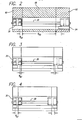
- FIG. 2 schematically shows a conventional prior art printer in which all printhead servicing takes place at a printhead servicing station 62 located at the right side of the printer. Accordingly, since each printhead must be serviced in a single service station 62 containing multiple printhead servicing functions (schematically shown as 64) including wiping and priming functions through which the printheads must be moved, the right hand printhead overtravel zone (also depicted by 62) is somewhat longer than the left hand overtravel zone 60. The print zone is depicted by 66.
- the carriage overtravel zones 60, 62 are the zones occupied by the carriage at each side of the print zone and, if used for printhead servicing, are also referred to herein as servicing zones 60, 62.
- the width of the carriage overtravel zones is a critical part of proper functionality for an inkjet printer mechanism.
- Carriage overtravel permits the carriage 30 to decelerate, change direction and accelerate to the desired carriage velocity before ink drops are ejected onto the media. Ejection of ink drops while the carriage 30 and printheads 32, 34 accelerate or decelerate is undesirable due to the difficulty in accurately timing the exact moment when ejection or firing must occur to insure accurate dot placement during printing.
- the width of the carriage printhead service zone 62 as seen in the prior art arrangement illustrated in Fig. 2 is necessarily greater than the width of the carriage overtravel zone 60 at the left end of the path of carriage movement where no servicing takes place.
- the total operational width W T of the printer 10 is reduced according to the present invention by the servicing selected printheads at separate printhead service stations 60, 62 at each end of the path of carriage travel.
- one or more wipers 70, 72 for servicing a single printhead are provided in position to wipe the leading printhead or printheads on the carriage and printheads after printing has taken place.
- the right hand wiper 72 ( Figure 6) wipes the leading or right hand (for example color) printhead 34 mounted on the right side of the printhead carriage 30 after printing in the left to right direction but does not wipe the other 32 (e.g., black) printhead.
- the left hand wiper 70 wipes the leading (black) printhead 32 mounted on the left side of the printhead carriage after printing in the right to left direction has taken place.
- the width of the right side overtravel or servicing zone 62 is reduced as compared to the prior art zone 62 shown in Fig. 2 resulting in a reduction in total operational width W T of the printer since wiping of only the leading printhead (or printheads) takes place therein.
- the width of the left overtravel zone 60 is not increased by adding the servicing functions therein since only the leading printhead or printheads are service.
- Each service station 60, 62 may also include a printhead capping and priming function 80 in addition to the wiping function.
- the capping function 80 may include a number of caps and spittoons equal in number to half of the number of printheads to be primed so that the individual printheads can be positioned over individual caps and spittoons whereby ink may be ejected or sucked from the printheads to enter the spittoons when priming the printheads.
- the details of the caps and spittoons and inkjet priming methods are not necessary to a full understanding of the invention described and claimed herein.
- a further reduction in the total operational width W T of the printer 10 can be accomplished by using the teachings set forth above with respect to the invention illustrated in Figures 3-6 together with the technique of printing with only the trailing one of the two printheads shown.
- the left printhead 32 e.g., black
- the right (color) printhead 34 is controlled to print only when the carriage and printheads travel to the left.
- the method of printing described with reference to Fig. 4 is not limited to printers having only two printheads.
- the leading one or two printheads need to be deactivated when, for example, a carriage having four separate printheads mounted thereon is used, i.e., the trailing one or two printheads always accomplish the printing function while the leading one or two printheads are de-actuated, the reverse mode of operation being used when printing in the opposite direction takes place.
- Figure 6 also shows an optional centrally located printhead priming and capping station 90 in schematic form which is positioned in the print zone.
- the carriage 30 and associated printheads 32, 34 may be positioned over the central capping station 90 during period of non-operation of the printer so that the printheads can be primed, capped and protected from drying out, ingress of dirt and the like.
- the central capping station 90 may include a number of caps and spittoons equal in number to the number of printheads on the carriage 30 so that all printheads can be positioned over individual caps and spittoons.
Landscapes
- Ink Jet (AREA)
Claims (14)
- Ein Verfahren zum Drucken und Warten von zumindest zwei Tintenstrahldruckköpfen (32, 34) bei einem Tintenstrahldrucker (10), das folgende Schritte aufweist:a) Positionieren eines Druckkopfwagens (30), der zumindest zwei Tintenstrahldruckköpfe darauf aufweist, an einem ersten Ende eines Wegs einer Wagenbewegung;b) Beschleunigen des Wagens und der Druckköpfe von einer ersten Ruheposition in einer ersten Richtung durch eine erste Beschleunigungszone zu einer Druckzone;c) Ausstoßen von Tinte von zumindest einem der Druckköpfe, um zu drucken, wenn der Wagen und die Druckköpfe sich in der ersten Richtung durch die Druckzone bewegen;d) Warten zumindest eines der Druckköpfe, jedoch weniger als aller Druckköpfe an einer ersten Wartungsstation (62), die einen Druckkopfwischer aufweist, der an einem zweiten Ende des Wegs einer Wagenbewegung positioniert ist;e) Beschleunigen des Wagens und der Druckköpfe von einer zweiten Ruheposition in einer zweiten Richtung durch eine zweite Beschleunigungszone zu der Druckzone;f) Ausstoßen von Tinte von zumindest einem der Druckköpfe, um zu drucken, wenn der Wagen und die Druckköpfe sich in der zweiten Richtung durch die Druckzone bewegen; undg) Warten zumindest eines anderen der Druckköpfe an einer zweiten Wartungsstation (60), die einen Druckkopfwischer aufweist, der an dem ersten Ende des Wegs einer Wagenbewegung positioniert ist.
- Das Verfahren gemäß Anspruch 1, bei dem der Weg einer Bewegung des Wagens (30) linear ist.
- Das Verfahren gemäß Anspruch 2, bei dem der vordere Druckkopf durch ein Wischen während einer Bewegung des Wagens (30) und der Druckköpfe (32, 34) in der ersten und der zweiten Richtung nach einem Drucken gewartet wird.
- Das Verfahren gemäß Anspruch 3, das die Schritte eines Deaktivierens eines vorderen Druckkopfs und eines Druckens mit einem hinteren Druckkopf während einer Druckkopfbewegung über die Druckzone aufweist.
- Das Verfahren gemäß Anspruch 3, bei dem der vordere Druckkopf an der zugeordneten Wartungsstation (60, 62) durch ein Abwischen und Abdecken (80) des Druckkopfs gewartet wird.
- Das Verfahren gemäß Anspruch 5, das ferner die Schritte eines Bewirkens eines Tintenflusses von dem Druckkopf aufweist, um den Druckkopf an der zugeordneten Wartungsstation (60) (62) vorzubereiten.
- Ein Tintenstrahldrucker (10), der ein Chassis (12), einen Druckkopfwagen (30), der während eines Druckens quer zu dem Chassis über eine Druckzone bewegbar ist, Tintenstrahldruckköpfe, die an dem Wagen befestigt sind, und eine Druckkopfwartungseinrichtung an dem Chassis zum Warten der Druckköpfe (32, 34) aufweist, wobei die Druckkopfwartungseinrichtung getrennte Wartungsstationen (60, 62) aufweist, die jeweils aus einem ersten Druckkopfwischer, der außerhalb der Druckzone lateral von einer ersten Seite der Druckzone beabstandet positioniert ist, zum Abwischen zumindest eines der Druckköpfe, jedoch weniger als aller Druckköpfe, und einem zweiten Druckkopfwischer, der außerhalb der Druckzone lateral von einer zweiten Seite der Druckzone beabstandet positioniert ist, zum Abwischen zumindest eines anderen der Druckköpfe gebildet sind.
- Der Drucker (10) gemäß Anspruch 7, bei dem eine Druckkopfbeschleunigungszone als die Entfernung zwischen der vorderen Kante des Druckkopfs, die der Druckzone am nächsten ist, wenn sich der Wagen (30) an dem Ende seines Bewegungswegs befindet, und der am nächsten gelegenen Kante der Druckzone definiert ist, wobei der Drucker Druckkopfbeschleunigungszonen an jedem Ende des Wegs einer Wagenbewegung von im Wesentlichen gleicher Länge aufweist.
- Der Drucker (10) gemäß Anspruch 8, bei dem die Druckkopfwischer (70, 72) lateral von den Beschleunigungszonen beabstandet sind und an dem Chassis (12) positioniert sind, um die Betriebsbreite des zugeordneten Druckkopfs abzuwischen, wenn sich derselbe zu dem Ende seines Bewegungswegs bewegt.
- Der Drucker (10) gemäß Anspruch 9, der ferner eine Vorrichtung zur Druckkopfvorbereitung und -abdeckung (80) bei den Wartungsstationen (60, 62) aufweist.
- Der Drucker (10) gemäß Anspruch 7, der ferner eine Druckkopfsteuereinrichtung zum Deaktivieren eines vorderen Druckkopfs und zum Drucken mit einem hinteren Druckkopf, wenn sich der Wagen (30) in der ersten Richtung bewegt, und zum Deaktivieren eines anderen vorderen Druckkopfs und zum Drucken mit einem anderen hinteren Druckkopf, wenn sich der Wagen in einer zweiten Richtung bewegt, aufweist.
- Der Drucker (10) gemäß Anspruch 11, bei dem eine Druckkopfbeschleunigungszone als die Entfernung zwischen der vorderen Kante des Druckkopfs, die am weitesten von der Druckzone entfernt ist, wenn sich der Wagen (30) an dem Ende seines Bewegungswegs befindet, und der am nächsten gelegenen Kante der Druckzone definiert ist, wobei der Drucker Druckkopfbeschleunigungszonen an jedem Ende des Wegs einer Wagenbewegung von im Wesentlichen gleicher Länge aufweist.
- Der Drucker (10) gemäß Anspruch 12, bei dem die Wischer (70, 72) in den Beschleunigungszonen positioniert sind.
- Der Drucker (10) gemäß Anspruch 13, der ferner eine Vorrichtung zur Druckkopfvorbereitung und -abdeckung (80) bei jeder der Wartungsstationen (60, 62) aufweist.
Applications Claiming Priority (2)
| Application Number | Priority Date | Filing Date | Title |
|---|---|---|---|
| US392346 | 1999-09-07 | ||
| US09/392,346 US6139128A (en) | 1999-09-07 | 1999-09-07 | Discrete pen wiping and pen specific print direction to reduce size of inkjet printer |
Publications (3)
| Publication Number | Publication Date |
|---|---|
| EP1083051A2 EP1083051A2 (de) | 2001-03-14 |
| EP1083051A3 EP1083051A3 (de) | 2001-06-13 |
| EP1083051B1 true EP1083051B1 (de) | 2006-08-16 |
Family
ID=23550224
Family Applications (1)
| Application Number | Title | Priority Date | Filing Date |
|---|---|---|---|
| EP00109626A Expired - Lifetime EP1083051B1 (de) | 1999-09-07 | 2000-05-05 | Getrennter, von der Druckkopfrichtung abhängiger Druckkopfwischvorgang zur Reduzierung der Tintenstrahldruckergrösse |
Country Status (5)
| Country | Link |
|---|---|
| US (1) | US6139128A (de) |
| EP (1) | EP1083051B1 (de) |
| JP (1) | JP2001088314A (de) |
| KR (1) | KR100659813B1 (de) |
| DE (1) | DE60030054D1 (de) |
Families Citing this family (12)
| Publication number | Priority date | Publication date | Assignee | Title |
|---|---|---|---|---|
| TW492414U (en) * | 2001-07-25 | 2002-06-21 | Acer Comm & Amp Multimedia Inc | Ink-jet printing module with cleaning device and shielding device located at both sides of the printing stage |
| JP3868781B2 (ja) * | 2001-09-28 | 2007-01-17 | シャープ株式会社 | 印字装置 |
| JP2004001464A (ja) * | 2002-04-12 | 2004-01-08 | Sharp Corp | 印字装置 |
| US6755504B2 (en) * | 2002-04-26 | 2004-06-29 | Hewlett-Packard Development Company. Lp. | Independent wiping of printhead |
| US6761428B2 (en) * | 2002-07-22 | 2004-07-13 | Hewlett-Packard Development Company, L.P. | Independent wiping of printhead |
| GB0308203D0 (en) * | 2003-04-09 | 2003-05-14 | Hewlett Packard Co | Servicing printheads |
| US7410317B2 (en) * | 2003-08-26 | 2008-08-12 | Oki Data Corporation | Method for processing medium, image processing apparatus, and printer apparatus |
| US7222934B2 (en) * | 2004-11-22 | 2007-05-29 | Xerox Corporation | Method and apparatus for mounting an inkjet printhead |
| KR101484272B1 (ko) * | 2008-11-28 | 2015-01-20 | 주식회사 디엠에스 | 약액 예비토출장치 |
| GB0907362D0 (en) | 2009-04-29 | 2009-06-10 | Ten Cate Itex B V | Print carriage |
| JP5534349B2 (ja) * | 2011-02-09 | 2014-06-25 | 横河電機株式会社 | pHセンサおよびpH測定方法 |
| JP6331759B2 (ja) * | 2014-06-26 | 2018-05-30 | セイコーエプソン株式会社 | インクジェットプリンタ |
Family Cites Families (9)
| Publication number | Priority date | Publication date | Assignee | Title |
|---|---|---|---|---|
| WO1991010570A1 (de) * | 1990-01-09 | 1991-07-25 | Siemens Aktiengesellschaft | Saug- und abdeckeinrichtung zum absaugen von tinte aus tintendruckköpfen eines tintendruckwerkes und zum abdecken der tintendruckköpfe |
| JPH04197757A (ja) * | 1990-11-29 | 1992-07-17 | Canon Inc | 画像出力装置 |
| JPH06198897A (ja) * | 1992-12-28 | 1994-07-19 | Canon Inc | インクジェット記録装置 |
| JPH07125223A (ja) * | 1993-06-23 | 1995-05-16 | Nec Corp | インクジェットプリンタ回復装置 |
| US5793388A (en) * | 1995-03-06 | 1998-08-11 | Hewlett-Packard Company | Customized printhead servicing for different printer conditions |
| US5749662A (en) * | 1995-12-15 | 1998-05-12 | Fuji Photo Film Co., Ltd. | Printing method for recording apparatus with multiple print heads |
| EP0822086B1 (de) * | 1996-07-30 | 2002-11-20 | Canon Kabushiki Kaisha | Aufzeichnungsgerät und Gradationsaufzeichnungsverfahren in geteilten oder überlappenden Gebieten des Aufzeichnungsmediums |
| JP2000015843A (ja) * | 1998-06-30 | 2000-01-18 | Brother Ind Ltd | 印刷装置 |
| JP3161534B2 (ja) * | 1998-11-27 | 2001-04-25 | セイコーエプソン株式会社 | インクジェット式記録装置 |
-
1999
- 1999-09-07 US US09/392,346 patent/US6139128A/en not_active Expired - Lifetime
-
2000
- 2000-05-05 DE DE60030054T patent/DE60030054D1/de not_active Expired - Lifetime
- 2000-05-05 EP EP00109626A patent/EP1083051B1/de not_active Expired - Lifetime
- 2000-09-04 KR KR1020000052145A patent/KR100659813B1/ko not_active IP Right Cessation
- 2000-09-07 JP JP2000270865A patent/JP2001088314A/ja not_active Withdrawn
Also Published As
| Publication number | Publication date |
|---|---|
| KR20010030258A (ko) | 2001-04-16 |
| KR100659813B1 (ko) | 2006-12-19 |
| US6139128A (en) | 2000-10-31 |
| JP2001088314A (ja) | 2001-04-03 |
| EP1083051A3 (de) | 2001-06-13 |
| DE60030054D1 (de) | 2006-09-28 |
| EP1083051A2 (de) | 2001-03-14 |
Similar Documents
| Publication | Publication Date | Title |
|---|---|---|
| EP0995603B1 (de) | Apparat und Verfahren zum Drucken eines randloses Bildes | |
| JP3969933B2 (ja) | 液体インクプリントされたシートを支持及びスタックする方法及び機構、及びプリンティングシステム | |
| EP1882591B1 (de) | Bilderzeugungsvorrichtung und Betriebssteuerungsverfahren dafür | |
| EP1083051B1 (de) | Getrennter, von der Druckkopfrichtung abhängiger Druckkopfwischvorgang zur Reduzierung der Tintenstrahldruckergrösse | |
| JP3391924B2 (ja) | 画像記録装置 | |
| JP6921662B2 (ja) | インクジェット記録装置 | |
| EP1393912B1 (de) | Anordnung und Verfahren zur Wartung eines nicht-abtastenden Druckkopfes | |
| US20040100521A1 (en) | Stalagmite dissolving spittoon system for inkjet printheads | |
| JP3909714B2 (ja) | インクジェット記録装置及び予備吐出制御方法 | |
| US6669325B2 (en) | Apparatus and method for placing fluid droplets onto an object | |
| JP2010523373A (ja) | インクジェットプリンタの動作メカニズム | |
| JP3483410B2 (ja) | インクジェット記録装置 | |
| EP0913262A1 (de) | Reinigungsvorrichtung mit schmalen und breiten Wischblättern für Tintenstrahldruckköpfe | |
| JP3165722B2 (ja) | インクジェット装置 | |
| JP3823991B2 (ja) | インクジェット記録装置及び予備吐出制御方法 | |
| US7021743B2 (en) | Printhead service station | |
| US20020171707A1 (en) | Ink jet printing apparatus and wiping method therefor | |
| US7926906B2 (en) | Ink jet printing apparatus and ink absorber recovery method | |
| US6755505B2 (en) | Carriage dam for inkjet printer | |
| US20050122374A1 (en) | Inkjet printer | |
| US6588873B1 (en) | Printing apparatus and method | |
| EP0775586A1 (de) | Minimalisierung der Breite des Tintenstrahlkopfwagens | |
| EP4311678A2 (de) | Flüssigkeitsausstossvorrichtung | |
| JPH07125223A (ja) | インクジェットプリンタ回復装置 | |
| JP3409043B2 (ja) | インクジェットプリンタおよび印字ヘッド |
Legal Events
| Date | Code | Title | Description |
|---|---|---|---|
| PUAI | Public reference made under article 153(3) epc to a published international application that has entered the european phase |
Free format text: ORIGINAL CODE: 0009012 |
|
| AK | Designated contracting states |
Kind code of ref document: A2 Designated state(s): DE FR GB |
|
| AX | Request for extension of the european patent |
Free format text: AL;LT;LV;MK;RO;SI |
|
| PUAL | Search report despatched |
Free format text: ORIGINAL CODE: 0009013 |
|
| RAP1 | Party data changed (applicant data changed or rights of an application transferred) |
Owner name: HEWLETT-PACKARD COMPANY, A DELAWARE CORPORATION |
|
| AK | Designated contracting states |
Kind code of ref document: A3 Designated state(s): AT BE CH CY DE DK ES FI FR GB GR IE IT LI LU MC NL PT SE |
|
| AX | Request for extension of the european patent |
Free format text: AL;LT;LV;MK;RO;SI |
|
| 17P | Request for examination filed |
Effective date: 20010719 |
|
| AKX | Designation fees paid |
Free format text: DE FR GB |
|
| 17Q | First examination report despatched |
Effective date: 20050315 |
|
| GRAP | Despatch of communication of intention to grant a patent |
Free format text: ORIGINAL CODE: EPIDOSNIGR1 |
|
| GRAS | Grant fee paid |
Free format text: ORIGINAL CODE: EPIDOSNIGR3 |
|
| GRAA | (expected) grant |
Free format text: ORIGINAL CODE: 0009210 |
|
| AK | Designated contracting states |
Kind code of ref document: B1 Designated state(s): DE FR GB |
|
| REG | Reference to a national code |
Ref country code: GB Ref legal event code: FG4D |
|
| REF | Corresponds to: |
Ref document number: 60030054 Country of ref document: DE Date of ref document: 20060928 Kind code of ref document: P |
|
| PG25 | Lapsed in a contracting state [announced via postgrant information from national office to epo] |
Ref country code: DE Free format text: LAPSE BECAUSE OF FAILURE TO SUBMIT A TRANSLATION OF THE DESCRIPTION OR TO PAY THE FEE WITHIN THE PRESCRIBED TIME-LIMIT Effective date: 20061117 |
|
| EN | Fr: translation not filed | ||
| PLBE | No opposition filed within time limit |
Free format text: ORIGINAL CODE: 0009261 |
|
| STAA | Information on the status of an ep patent application or granted ep patent |
Free format text: STATUS: NO OPPOSITION FILED WITHIN TIME LIMIT |
|
| 26N | No opposition filed |
Effective date: 20070518 |
|
| PG25 | Lapsed in a contracting state [announced via postgrant information from national office to epo] |
Ref country code: FR Free format text: LAPSE BECAUSE OF FAILURE TO SUBMIT A TRANSLATION OF THE DESCRIPTION OR TO PAY THE FEE WITHIN THE PRESCRIBED TIME-LIMIT Effective date: 20070511 |
|
| PG25 | Lapsed in a contracting state [announced via postgrant information from national office to epo] |
Ref country code: FR Free format text: LAPSE BECAUSE OF FAILURE TO SUBMIT A TRANSLATION OF THE DESCRIPTION OR TO PAY THE FEE WITHIN THE PRESCRIBED TIME-LIMIT Effective date: 20060816 |
|
| REG | Reference to a national code |
Ref country code: GB Ref legal event code: 732E Free format text: REGISTERED BETWEEN 20120329 AND 20120404 |
|
| PGFP | Annual fee paid to national office [announced via postgrant information from national office to epo] |
Ref country code: GB Payment date: 20130424 Year of fee payment: 14 |
|
| GBPC | Gb: european patent ceased through non-payment of renewal fee |
Effective date: 20140505 |
|
| PG25 | Lapsed in a contracting state [announced via postgrant information from national office to epo] |
Ref country code: GB Free format text: LAPSE BECAUSE OF NON-PAYMENT OF DUE FEES Effective date: 20140505 |