EP1083051B1 - Separarate print head wiping operation dependent upon print head direction to reduce inkjet printer size - Google Patents
Separarate print head wiping operation dependent upon print head direction to reduce inkjet printer sizeInfo
- Publication number
- EP1083051B1 EP1083051B1 EP00109626A EP00109626A EP1083051B1 EP 1083051 B1 EP1083051 B1 EP 1083051B1 EP 00109626 A EP00109626 A EP 00109626A EP 00109626 A EP00109626 A EP 00109626A EP 1083051 B1 EP1083051 B1 EP 1083051B1
- Authority
- EP
- European Patent Office
- Prior art keywords
- printhead
- carriage
- printheads
- printer
- zone
- Prior art date
- Legal status (The legal status is an assumption and is not a legal conclusion. Google has not performed a legal analysis and makes no representation as to the accuracy of the status listed.)
- Expired - Lifetime
Links
Images


Classifications
-
- B—PERFORMING OPERATIONS; TRANSPORTING
- B41—PRINTING; LINING MACHINES; TYPEWRITERS; STAMPS
- B41J—TYPEWRITERS; SELECTIVE PRINTING MECHANISMS, i.e. MECHANISMS PRINTING OTHERWISE THAN FROM A FORME; CORRECTION OF TYPOGRAPHICAL ERRORS
- B41J2/00—Typewriters or selective printing mechanisms characterised by the printing or marking process for which they are designed
- B41J2/22—Typewriters or selective printing mechanisms characterised by the printing or marking process for which they are designed characterised by selective application of impact or pressure on a printing material or impression-transfer material
- B41J2/23—Typewriters or selective printing mechanisms characterised by the printing or marking process for which they are designed characterised by selective application of impact or pressure on a printing material or impression-transfer material using print wires
- B41J2/235—Print head assemblies
-
- B—PERFORMING OPERATIONS; TRANSPORTING
- B41—PRINTING; LINING MACHINES; TYPEWRITERS; STAMPS
- B41J—TYPEWRITERS; SELECTIVE PRINTING MECHANISMS, i.e. MECHANISMS PRINTING OTHERWISE THAN FROM A FORME; CORRECTION OF TYPOGRAPHICAL ERRORS
- B41J2/00—Typewriters or selective printing mechanisms characterised by the printing or marking process for which they are designed
- B41J2/005—Typewriters or selective printing mechanisms characterised by the printing or marking process for which they are designed characterised by bringing liquid or particles selectively into contact with a printing material
- B41J2/01—Ink jet
- B41J2/135—Nozzles
- B41J2/165—Preventing or detecting of nozzle clogging, e.g. cleaning, capping or moistening for nozzles
- B41J2/16517—Cleaning of print head nozzles
- B41J2/16535—Cleaning of print head nozzles using wiping constructions
- B41J2/16538—Cleaning of print head nozzles using wiping constructions with brushes or wiper blades perpendicular to the nozzle plate
Definitions
- the present invention relates to the art of computer driven printers, particularly color inkjet printers of desktop size in which reduction of the footprint of the printer enables more efficient utilization of available space.
- Printers of this type have a printhead carriage which is mounted for reciprocal movement on the printer chassis in a direction orthogonal to the direction of movement of the paper or other medium on which printing is to take place through the printer.
- the printer carriage of a color printer typically has a black ink and one or more color thermal inkjet printheads removably mounted thereon and a printhead servicing station at one end of the path of carriage travel at which the printheads may be wiped, primed and capped during periods of non-use.
- Printhead servicing stations have a finite width which is dictated primarily by the number of printheads to be serviced and the number of printhead servicing functions to be performed.
- the printhead servicing station may be designed with printhead wipers, caps and spittoons into which ink is ejected during printhead priming.
- the servicing elements may be mounted in stationary position on printer or, as is preferred, the servicing elements may be moveable on a sled or other support to the servicing position and moveable away from the servicing position to an access position where the servicing elements may be repaired or replaced. It will thus be appreciated by persons skilled in the art that elimination of one or more of these servicing functions at the service station enables the width of the service station to be reduced thus resulting in a printer of smaller size and footprint.
- JP-A-07125223 discloses an inkjet printer having a cap mechanism for preventing the evaporation of ink from two printheads and cleaning plates for cleaning the printheads.
- the capping device and the cleaning plates are arranged within the printing area of the inkjet printer in a retractable manner.
- EP 0 822 086 A2 discloses an inkjet printer having two printheads supported by a printhead carriage. A single wiper for cleaning both printheads is arranged in the recording region of both printheads. The wiper can be protruded in the scanning path of the corresponding head in order to perform the wiping operation.
- Discharge receptacles for performing a section recovery operation of both printheads are arranged outside of the respective recording regions of the respective printheads.
- JP-A-06198897 discloses an inkjet printer having four printheads held by a printhead carriage. Two cleaning blades, each for cleaning all of the printheads, are respectively arranged to either side of the print region.
- EP-A-0 968 826 A2 discloses an inkjet printing apparatus having separate flushing areas arranged outwardly of the printing area.
- the present invention is based on the object of providing a method of printing and servicing the printheads in an inkjet printer and an inkjet printer enabling a more efficient utilization of available space.
- FIG. 1 shows a desk top inkjet printer 10 having a chassis 12 on which a transversely extending carriage support or supports 20, 22 are mounted and a carriage 30 is slidably mounted on the support or supports for linear back and forth movement transversely of the printer 10.
- Two or more removable printheads 32, 34 are mounted on the carriage 30 and eject ink downwardly onto the media on which printing is to take place.
- the printer also may have an upper single sheet paper tray 16, a lower paper supply tray 18 for holding a stack of paper or other media on which printing is to take place, a control center 40, a print zone cover 50 and, pursuant to the invention, inkjet printhead servicing stations 60, 62 (only one of which is seen in Fig. 1) at each end of the print zone.
- the total operational width W T of a printer is comprised of the sum of the width of the print zone (W PZ ) plus twice the width of the printer carriage (2W C ) plus the width of two printhead carriage acceleration zones (2W AZ ).
- the full width of the print zone W PZ is ordinarily not used during printing.
- the paper or other media on which printing is to take place has a width W MD and, at each edge of the media, is usually left a margin W MG in which no printing occurs.
- the print zone has a width W PZ which is suitable for printing on media of different widths and accommodates margins of different widths which remain un-printed.
- the printer carriage 30 having two or more separate printheads 32, 34 thereon must first accelerate from a terminal position at either end of the path of carriage travel to a substantially constant printing velocity before accurate printing without undue compensation for acceleration and deceleration of the printheads can take place. Accordingly, acceleration zones W AZ are depicted at each end of the print zone.
- the schematic drawings shown herein show only two printheads 32, 34 on the carriage 30 (typically the left hand printhead is black ink and the right hand printhead is color ink), the teachings of the invention are not limited to the embodiment shown for illustrative purposes since it is not unusual to mount four or more printheads containing ink of different colors side by side on the printhead carriage 30.
- FIG. 2 schematically shows a conventional prior art printer in which all printhead servicing takes place at a printhead servicing station 62 located at the right side of the printer. Accordingly, since each printhead must be serviced in a single service station 62 containing multiple printhead servicing functions (schematically shown as 64) including wiping and priming functions through which the printheads must be moved, the right hand printhead overtravel zone (also depicted by 62) is somewhat longer than the left hand overtravel zone 60. The print zone is depicted by 66.
- the carriage overtravel zones 60, 62 are the zones occupied by the carriage at each side of the print zone and, if used for printhead servicing, are also referred to herein as servicing zones 60, 62.
- the width of the carriage overtravel zones is a critical part of proper functionality for an inkjet printer mechanism.
- Carriage overtravel permits the carriage 30 to decelerate, change direction and accelerate to the desired carriage velocity before ink drops are ejected onto the media. Ejection of ink drops while the carriage 30 and printheads 32, 34 accelerate or decelerate is undesirable due to the difficulty in accurately timing the exact moment when ejection or firing must occur to insure accurate dot placement during printing.
- the width of the carriage printhead service zone 62 as seen in the prior art arrangement illustrated in Fig. 2 is necessarily greater than the width of the carriage overtravel zone 60 at the left end of the path of carriage movement where no servicing takes place.
- the total operational width W T of the printer 10 is reduced according to the present invention by the servicing selected printheads at separate printhead service stations 60, 62 at each end of the path of carriage travel.
- one or more wipers 70, 72 for servicing a single printhead are provided in position to wipe the leading printhead or printheads on the carriage and printheads after printing has taken place.
- the right hand wiper 72 ( Figure 6) wipes the leading or right hand (for example color) printhead 34 mounted on the right side of the printhead carriage 30 after printing in the left to right direction but does not wipe the other 32 (e.g., black) printhead.
- the left hand wiper 70 wipes the leading (black) printhead 32 mounted on the left side of the printhead carriage after printing in the right to left direction has taken place.
- the width of the right side overtravel or servicing zone 62 is reduced as compared to the prior art zone 62 shown in Fig. 2 resulting in a reduction in total operational width W T of the printer since wiping of only the leading printhead (or printheads) takes place therein.
- the width of the left overtravel zone 60 is not increased by adding the servicing functions therein since only the leading printhead or printheads are service.
- Each service station 60, 62 may also include a printhead capping and priming function 80 in addition to the wiping function.
- the capping function 80 may include a number of caps and spittoons equal in number to half of the number of printheads to be primed so that the individual printheads can be positioned over individual caps and spittoons whereby ink may be ejected or sucked from the printheads to enter the spittoons when priming the printheads.
- the details of the caps and spittoons and inkjet priming methods are not necessary to a full understanding of the invention described and claimed herein.
- a further reduction in the total operational width W T of the printer 10 can be accomplished by using the teachings set forth above with respect to the invention illustrated in Figures 3-6 together with the technique of printing with only the trailing one of the two printheads shown.
- the left printhead 32 e.g., black
- the right (color) printhead 34 is controlled to print only when the carriage and printheads travel to the left.
- the method of printing described with reference to Fig. 4 is not limited to printers having only two printheads.
- the leading one or two printheads need to be deactivated when, for example, a carriage having four separate printheads mounted thereon is used, i.e., the trailing one or two printheads always accomplish the printing function while the leading one or two printheads are de-actuated, the reverse mode of operation being used when printing in the opposite direction takes place.
- Figure 6 also shows an optional centrally located printhead priming and capping station 90 in schematic form which is positioned in the print zone.
- the carriage 30 and associated printheads 32, 34 may be positioned over the central capping station 90 during period of non-operation of the printer so that the printheads can be primed, capped and protected from drying out, ingress of dirt and the like.
- the central capping station 90 may include a number of caps and spittoons equal in number to the number of printheads on the carriage 30 so that all printheads can be positioned over individual caps and spittoons.
Description
- The present invention relates to the art of computer driven printers, particularly color inkjet printers of desktop size in which reduction of the footprint of the printer enables more efficient utilization of available space. Printers of this type have a printhead carriage which is mounted for reciprocal movement on the printer chassis in a direction orthogonal to the direction of movement of the paper or other medium on which printing is to take place through the printer. The printer carriage of a color printer typically has a black ink and one or more color thermal inkjet printheads removably mounted thereon and a printhead servicing station at one end of the path of carriage travel at which the printheads may be wiped, primed and capped during periods of non-use.
- Printhead servicing stations have a finite width which is dictated primarily by the number of printheads to be serviced and the number of printhead servicing functions to be performed. The printhead servicing station may be designed with printhead wipers, caps and spittoons into which ink is ejected during printhead priming. The servicing elements may be mounted in stationary position on printer or, as is preferred, the servicing elements may be moveable on a sled or other support to the servicing position and moveable away from the servicing position to an access position where the servicing elements may be repaired or replaced. It will thus be appreciated by persons skilled in the art that elimination of one or more of these servicing functions at the service station enables the width of the service station to be reduced thus resulting in a printer of smaller size and footprint.
- JP-A-07125223 discloses an inkjet printer having a cap mechanism for preventing the evaporation of ink from two printheads and cleaning plates for cleaning the printheads. In order to reduce the required space for the capping and cleaning operations, the capping device and the cleaning plates are arranged within the printing area of the inkjet printer in a retractable manner.
- EP 0 822 086 A2 discloses an inkjet printer having two printheads supported by a printhead carriage. A single wiper for cleaning both printheads is arranged in the recording region of both printheads. The wiper can be protruded in the scanning path of the corresponding head in order to perform the wiping operation.
- Discharge receptacles for performing a section recovery operation of both printheads are arranged outside of the respective recording regions of the respective printheads.
- JP-A-06198897 discloses an inkjet printer having four printheads held by a printhead carriage. Two cleaning blades, each for cleaning all of the printheads, are respectively arranged to either side of the print region.
- The prior, non-pre-published EP-A-0 968 826 A2 discloses an inkjet printing apparatus having separate flushing areas arranged outwardly of the printing area.
- The present invention is based on the object of providing a method of printing and servicing the printheads in an inkjet printer and an inkjet printer enabling a more efficient utilization of available space.
- This object is achieved by a method in accordance with claim 1 and by an inkjet printer in accordance with claim 7.
-
- Figure 1 is a perspective view of a desktop size inkjet printer.
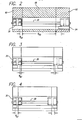
- Figure 2 is a schematic plan view of a typical prior art printer architecture including a printhead carriage having two pens thereon and a service station at one side of the printer.
- Figure 3 is a schematic plan view of a two pen printer according to a first embodiment of the invention having printhead service stations at each side of the printer.
- Figure 4 is a schematic plan view of the printer of Fig. 3 further modified to incorporate pen specific printing.
- Figure 5 is a schematic elevation view of the prior art printer of Fig. 2 showing distancing callouts therefor.
- Figure 6 is a schematic elevation view of the printer of Fig. 3 showing distancing callouts therefor.
- The perspective view of Fig. 1 shows a desk
top inkjet printer 10 having a chassis 12 on which a transversely extending carriage support or supports 20, 22 are mounted and acarriage 30 is slidably mounted on the support or supports for linear back and forth movement transversely of theprinter 10. Two or moreremovable printheads carriage 30 and eject ink downwardly onto the media on which printing is to take place. The printer also may have an upper singlesheet paper tray 16, a lower paper supply tray 18 for holding a stack of paper or other media on which printing is to take place, acontrol center 40, aprint zone cover 50 and, pursuant to the invention, inkjetprinthead servicing stations 60, 62 (only one of which is seen in Fig. 1) at each end of the print zone. - With reference to Figures 2 - 6, the total operational width WT of a printer is comprised of the sum of the width of the print zone (WPZ) plus twice the width of the printer carriage (2WC) plus the width of two printhead carriage acceleration zones (2WAZ). The full width of the print zone WPZ is ordinarily not used during printing. As seen in Fig. 5, the paper or other media on which printing is to take place has a width WMD and, at each edge of the media, is usually left a margin WMG in which no printing occurs. Thus, the print zone has a width WPZ which is suitable for printing on media of different widths and accommodates margins of different widths which remain un-printed.
- Also, as is well known to those skilled in the art, the
printer carriage 30 having two or moreseparate printheads printheads printhead carriage 30. - Figure 2 schematically shows a conventional prior art printer in which all printhead servicing takes place at a
printhead servicing station 62 located at the right side of the printer. Accordingly, since each printhead must be serviced in asingle service station 62 containing multiple printhead servicing functions (schematically shown as 64) including wiping and priming functions through which the printheads must be moved, the right hand printhead overtravel zone (also depicted by 62) is somewhat longer than the left handovertravel zone 60. The print zone is depicted by 66. The carriageovertravel zones servicing zones carriage 30 to decelerate, change direction and accelerate to the desired carriage velocity before ink drops are ejected onto the media. Ejection of ink drops while thecarriage 30 andprintheads printhead service zone 62 as seen in the prior art arrangement illustrated in Fig. 2 is necessarily greater than the width of the carriageovertravel zone 60 at the left end of the path of carriage movement where no servicing takes place. - As seen in Figures 3, 5 and 6 the total operational width WT of the
printer 10 is reduced according to the present invention by the servicing selected printheads at separateprinthead service stations more wipers 70, 72 for servicing a single printhead are provided in position to wipe the leading printhead or printheads on the carriage and printheads after printing has taken place. For example, the right hand wiper 72 (Figure 6) wipes the leading or right hand (for example color)printhead 34 mounted on the right side of theprinthead carriage 30 after printing in the left to right direction but does not wipe the other 32 (e.g., black) printhead. Conversely, theleft hand wiper 70 wipes the leading (black)printhead 32 mounted on the left side of the printhead carriage after printing in the right to left direction has taken place. Thus, the width of the right side overtravel orservicing zone 62 is reduced as compared to theprior art zone 62 shown in Fig. 2 resulting in a reduction in total operational width WT of the printer since wiping of only the leading printhead (or printheads) takes place therein. The width of the leftovertravel zone 60 is not increased by adding the servicing functions therein since only the leading printhead or printheads are service. - Each
service station priming function 80 in addition to the wiping function. As is known to those skilled in the art, thecapping function 80 may include a number of caps and spittoons equal in number to half of the number of printheads to be primed so that the individual printheads can be positioned over individual caps and spittoons whereby ink may be ejected or sucked from the printheads to enter the spittoons when priming the printheads. The details of the caps and spittoons and inkjet priming methods are not necessary to a full understanding of the invention described and claimed herein. - As seen in Figure 4, a further reduction in the total operational width WT of the
printer 10 can be accomplished by using the teachings set forth above with respect to the invention illustrated in Figures 3-6 together with the technique of printing with only the trailing one of the two printheads shown. For example, the left printhead 32 (e.g., black) is controlled to print only when the carriage and printheads travel to the right and the right (color)printhead 34 is controlled to print only when the carriage and printheads travel to the left. Here again it will be appreciated that the method of printing described with reference to Fig. 4 is not limited to printers having only two printheads. In its broadest aspects, if more than two printheads are provided, only the leading one or two printheads need to be deactivated when, for example, a carriage having four separate printheads mounted thereon is used, i.e., the trailing one or two printheads always accomplish the printing function while the leading one or two printheads are de-actuated, the reverse mode of operation being used when printing in the opposite direction takes place. - Figure 6 also shows an optional centrally located printhead priming and
capping station 90 in schematic form which is positioned in the print zone. Thecarriage 30 and associatedprintheads central capping station 90 during period of non-operation of the printer so that the printheads can be primed, capped and protected from drying out, ingress of dirt and the like. As is known to those skilled in the art, thecentral capping station 90 may include a number of caps and spittoons equal in number to the number of printheads on thecarriage 30 so that all printheads can be positioned over individual caps and spittoons. - It will be appreciated from the foregoing that the splitting of printhead wiping and priming functions into two
service stations - Persons skilled in the art will appreciate that various modifications of the preferred embodiment described above can be made and, for this reason, the intended scope of protection is defined by the claims which follow.
Claims (14)
- A method of printing and servicing at least two inkjet printheads (32, 34) in an inkjet printer (10) comprising the steps of:a) positioning a printhead carriage (30) having at least two inkjet printheads thereon at a first end of a path of carriage movement;b) accelerating said carriage and printheads from a first rest position in a first direction through a first acceleration zone to a print zone;c) ejecting ink from at least one of said printheads to print as said carriage and printheads move in said first direction through said print zone;d) servicing at least one of said printheads but less than all of said printheads at a first service station (62) comprising a printhead wiper positioned at a second end of said path of carriage movement;e) accelerating said carriage and printheads from a second rest position in a second direction through a second acceleration zone to said print zone;f) ejecting ink from at least one of said printheads to print as said carriage and printheads move in said second direction through said print zone; andg) servicing at least one other of said printheads at a second service station (60) comprising a printhead wiper positioned at said first end of said path of carriage movement.
- The method of claim 1, wherein said path of carriage (30) movement is linear.
- The method of claim 2, wherein the leading printhead is serviced by wiping during movement of said carriage (30) and printheads (32, 34) in said first and second directions after printing.
- The method of claim 3, comprising the steps of deactivating a leading printhead and printing with a trailing printhead during printhead movement across said print zone.
- The method of claim 3, wherein said leading printhead is serviced at the associated service station (60, 62) by wiping and capping (80) said printhead.
- The method of claim 5, further comprising the steps of causing ink flow from said printhead to prime said printhead at said associated service station (60) (62).
- An inkjet printer (10) having a chassis (12), a printhead carriage (30) moveable transversely of the chassis across a print zone during printing, inkjet printheads mounted on the carriage and printhead servicing means on said chassis for servicing said printheads (32, 34), wherein said printhead servicing means comprises separate servicing stations (60, 62) respectively comprised of a first printhead wiper positioned outside of said printing zone laterally spaced from a first side of said print zone for wiping at least one of said printheads but less than all of said printheads and a second printhead wiper positioned outside of said printing zone laterally spaced from a second side of said print zone for wiping at least one other of said printheads.
- The printer (10) of claim 7, wherein a printhead acceleration zone is defined as the distance between the leading edge of the printhead nearest the print zone when said carriage (30) is at the end of its path of travel and the nearest edge of the print zone, said printer having printhead acceleration zones at each end of the path of carriage travel of substantially equal length.
- The printer (10) of claim 8, wherein said printhead wipers (70, 72) are laterally spaced from said acceleration zones and are positioned on said chassis (12) to wipe the operational width of the associated printhead as it moves to the end of its path of travel.
- The printer (10) of claim 9, further comprising printhead priming and capping (80) apparatus in said servicing stations (60, 62).
- The printer (10) of claim 7, further comprising printhead control means for deactivating a leading printhead and printing with a trailing printhead when the carriage (30) moves in the first direction and for deactivating another leading printhead and printing with another trailing printhead when the carriage moves in a second direction.
- The printer (10) of claim 11, wherein a printhead acceleration zone is defined as the distance between the leading edge of the printhead farthest from the print zone when said carriage (30) is at the end of its path of travel and the nearest edge of the print zone, said printer having printhead acceleration zones at each end of the path of carriage travel of substantially equal length.
- The printer (10) of claim 12, wherein said wipers (70,72) are positioned in said acceleration zones.
- The printer (10) of claim 13, further comprising a printhead priming and capping (80) apparatus in each of said servicing stations (60, 62).
Applications Claiming Priority (2)
| Application Number | Priority Date | Filing Date | Title |
|---|---|---|---|
| US392346 | 1999-09-07 | ||
| US09/392,346 US6139128A (en) | 1999-09-07 | 1999-09-07 | Discrete pen wiping and pen specific print direction to reduce size of inkjet printer |
Publications (3)
| Publication Number | Publication Date |
|---|---|
| EP1083051A2 EP1083051A2 (en) | 2001-03-14 |
| EP1083051A3 EP1083051A3 (en) | 2001-06-13 |
| EP1083051B1 true EP1083051B1 (en) | 2006-08-16 |
Family
ID=23550224
Family Applications (1)
| Application Number | Title | Priority Date | Filing Date |
|---|---|---|---|
| EP00109626A Expired - Lifetime EP1083051B1 (en) | 1999-09-07 | 2000-05-05 | Separarate print head wiping operation dependent upon print head direction to reduce inkjet printer size |
Country Status (5)
| Country | Link |
|---|---|
| US (1) | US6139128A (en) |
| EP (1) | EP1083051B1 (en) |
| JP (1) | JP2001088314A (en) |
| KR (1) | KR100659813B1 (en) |
| DE (1) | DE60030054D1 (en) |
Families Citing this family (12)
| Publication number | Priority date | Publication date | Assignee | Title |
|---|---|---|---|---|
| TW492414U (en) * | 2001-07-25 | 2002-06-21 | Acer Comm & Amp Multimedia Inc | Ink-jet printing module with cleaning device and shielding device located at both sides of the printing stage |
| JP3868781B2 (en) * | 2001-09-28 | 2007-01-17 | シャープ株式会社 | Printing device |
| JP2004001464A (en) * | 2002-04-12 | 2004-01-08 | Sharp Corp | Printer |
| US6755504B2 (en) * | 2002-04-26 | 2004-06-29 | Hewlett-Packard Development Company. Lp. | Independent wiping of printhead |
| US6761428B2 (en) * | 2002-07-22 | 2004-07-13 | Hewlett-Packard Development Company, L.P. | Independent wiping of printhead |
| GB0308203D0 (en) * | 2003-04-09 | 2003-05-14 | Hewlett Packard Co | Servicing printheads |
| US7410317B2 (en) * | 2003-08-26 | 2008-08-12 | Oki Data Corporation | Method for processing medium, image processing apparatus, and printer apparatus |
| US7222934B2 (en) * | 2004-11-22 | 2007-05-29 | Xerox Corporation | Method and apparatus for mounting an inkjet printhead |
| KR101484272B1 (en) * | 2008-11-28 | 2015-01-20 | 주식회사 디엠에스 | chemical solution pre-discharging apparatus |
| GB0907362D0 (en) | 2009-04-29 | 2009-06-10 | Ten Cate Itex B V | Print carriage |
| JP5534349B2 (en) * | 2011-02-09 | 2014-06-25 | 横河電機株式会社 | pH sensor and pH measuring method |
| JP6331759B2 (en) * | 2014-06-26 | 2018-05-30 | セイコーエプソン株式会社 | Inkjet printer |
Family Cites Families (9)
| Publication number | Priority date | Publication date | Assignee | Title |
|---|---|---|---|---|
| DE59007404D1 (en) * | 1990-01-09 | 1994-11-10 | Eastman Kodak Co | SUCTION AND COVERING DEVICE FOR SUCTIONING INK FROM INK PRINT HEADS OF AN INK PRINTER AND FOR COVERING THE INK PRINT HEADS. |
| JPH04197757A (en) * | 1990-11-29 | 1992-07-17 | Canon Inc | Image output device |
| JPH06198897A (en) * | 1992-12-28 | 1994-07-19 | Canon Inc | Ink-jet recording device |
| JPH07125223A (en) * | 1993-06-23 | 1995-05-16 | Nec Corp | Restoration device of ink jet printer |
| US5793388A (en) * | 1995-03-06 | 1998-08-11 | Hewlett-Packard Company | Customized printhead servicing for different printer conditions |
| US5749662A (en) * | 1995-12-15 | 1998-05-12 | Fuji Photo Film Co., Ltd. | Printing method for recording apparatus with multiple print heads |
| EP0822086B1 (en) * | 1996-07-30 | 2002-11-20 | Canon Kabushiki Kaisha | Recording apparatus and method for gradation recording in divided or overlapped regions of a recording medium |
| JP2000015843A (en) * | 1998-06-30 | 2000-01-18 | Brother Ind Ltd | Printer |
| JP3161534B2 (en) * | 1998-11-27 | 2001-04-25 | セイコーエプソン株式会社 | Ink jet recording device |
-
1999
- 1999-09-07 US US09/392,346 patent/US6139128A/en not_active Expired - Lifetime
-
2000
- 2000-05-05 EP EP00109626A patent/EP1083051B1/en not_active Expired - Lifetime
- 2000-05-05 DE DE60030054T patent/DE60030054D1/en not_active Expired - Lifetime
- 2000-09-04 KR KR1020000052145A patent/KR100659813B1/en not_active IP Right Cessation
- 2000-09-07 JP JP2000270865A patent/JP2001088314A/en not_active Withdrawn
Also Published As
| Publication number | Publication date |
|---|---|
| JP2001088314A (en) | 2001-04-03 |
| US6139128A (en) | 2000-10-31 |
| EP1083051A3 (en) | 2001-06-13 |
| KR100659813B1 (en) | 2006-12-19 |
| EP1083051A2 (en) | 2001-03-14 |
| DE60030054D1 (en) | 2006-09-28 |
| KR20010030258A (en) | 2001-04-16 |
Similar Documents
| Publication | Publication Date | Title |
|---|---|---|
| EP0995603B1 (en) | Apparatus and method for printing borderless print image | |
| JP3969933B2 (en) | Method and mechanism for supporting and stacking liquid ink printed sheets and printing system | |
| EP1882591B1 (en) | Image forming apparatus and method to operatively control the same | |
| EP1083051B1 (en) | Separarate print head wiping operation dependent upon print head direction to reduce inkjet printer size | |
| JP3391924B2 (en) | Image recording device | |
| JP6921662B2 (en) | Inkjet recording device | |
| EP1393912B1 (en) | System and method for servicing non-scanning printhead | |
| US20040100521A1 (en) | Stalagmite dissolving spittoon system for inkjet printheads | |
| JP3909714B2 (en) | Ink jet recording apparatus and preliminary discharge control method | |
| US6669325B2 (en) | Apparatus and method for placing fluid droplets onto an object | |
| JP2010523373A (en) | Inkjet printer operating mechanism | |
| JP3483410B2 (en) | Ink jet recording device | |
| EP0913262A1 (en) | Narrow and wide wiper blade cleaning system for ink jet printheads | |
| JP3165722B2 (en) | Ink jet device | |
| JP3823991B2 (en) | Ink jet recording apparatus and preliminary discharge control method | |
| US7021743B2 (en) | Printhead service station | |
| US7404618B2 (en) | Inkjet printer | |
| US7926906B2 (en) | Ink jet printing apparatus and ink absorber recovery method | |
| US6755505B2 (en) | Carriage dam for inkjet printer | |
| US6588873B1 (en) | Printing apparatus and method | |
| EP0775586A1 (en) | Inkjet print carriage width minimization | |
| JPH07125223A (en) | Restoration device of ink jet printer | |
| JP3409043B2 (en) | Inkjet printer and print head | |
| JP2023005234A (en) | recording device | |
| JP2003291372A (en) | Inkjet recorder |
Legal Events
| Date | Code | Title | Description |
|---|---|---|---|
| PUAI | Public reference made under article 153(3) epc to a published international application that has entered the european phase |
Free format text: ORIGINAL CODE: 0009012 |
|
| AK | Designated contracting states |
Kind code of ref document: A2 Designated state(s): DE FR GB |
|
| AX | Request for extension of the european patent |
Free format text: AL;LT;LV;MK;RO;SI |
|
| PUAL | Search report despatched |
Free format text: ORIGINAL CODE: 0009013 |
|
| RAP1 | Party data changed (applicant data changed or rights of an application transferred) |
Owner name: HEWLETT-PACKARD COMPANY, A DELAWARE CORPORATION |
|
| AK | Designated contracting states |
Kind code of ref document: A3 Designated state(s): AT BE CH CY DE DK ES FI FR GB GR IE IT LI LU MC NL PT SE |
|
| AX | Request for extension of the european patent |
Free format text: AL;LT;LV;MK;RO;SI |
|
| 17P | Request for examination filed |
Effective date: 20010719 |
|
| AKX | Designation fees paid |
Free format text: DE FR GB |
|
| 17Q | First examination report despatched |
Effective date: 20050315 |
|
| GRAP | Despatch of communication of intention to grant a patent |
Free format text: ORIGINAL CODE: EPIDOSNIGR1 |
|
| GRAS | Grant fee paid |
Free format text: ORIGINAL CODE: EPIDOSNIGR3 |
|
| GRAA | (expected) grant |
Free format text: ORIGINAL CODE: 0009210 |
|
| AK | Designated contracting states |
Kind code of ref document: B1 Designated state(s): DE FR GB |
|
| REG | Reference to a national code |
Ref country code: GB Ref legal event code: FG4D |
|
| REF | Corresponds to: |
Ref document number: 60030054 Country of ref document: DE Date of ref document: 20060928 Kind code of ref document: P |
|
| PG25 | Lapsed in a contracting state [announced via postgrant information from national office to epo] |
Ref country code: DE Free format text: LAPSE BECAUSE OF FAILURE TO SUBMIT A TRANSLATION OF THE DESCRIPTION OR TO PAY THE FEE WITHIN THE PRESCRIBED TIME-LIMIT Effective date: 20061117 |
|
| EN | Fr: translation not filed | ||
| PLBE | No opposition filed within time limit |
Free format text: ORIGINAL CODE: 0009261 |
|
| STAA | Information on the status of an ep patent application or granted ep patent |
Free format text: STATUS: NO OPPOSITION FILED WITHIN TIME LIMIT |
|
| 26N | No opposition filed |
Effective date: 20070518 |
|
| PG25 | Lapsed in a contracting state [announced via postgrant information from national office to epo] |
Ref country code: FR Free format text: LAPSE BECAUSE OF FAILURE TO SUBMIT A TRANSLATION OF THE DESCRIPTION OR TO PAY THE FEE WITHIN THE PRESCRIBED TIME-LIMIT Effective date: 20070511 |
|
| PG25 | Lapsed in a contracting state [announced via postgrant information from national office to epo] |
Ref country code: FR Free format text: LAPSE BECAUSE OF FAILURE TO SUBMIT A TRANSLATION OF THE DESCRIPTION OR TO PAY THE FEE WITHIN THE PRESCRIBED TIME-LIMIT Effective date: 20060816 |
|
| REG | Reference to a national code |
Ref country code: GB Ref legal event code: 732E Free format text: REGISTERED BETWEEN 20120329 AND 20120404 |
|
| PGFP | Annual fee paid to national office [announced via postgrant information from national office to epo] |
Ref country code: GB Payment date: 20130424 Year of fee payment: 14 |
|
| GBPC | Gb: european patent ceased through non-payment of renewal fee |
Effective date: 20140505 |
|
| PG25 | Lapsed in a contracting state [announced via postgrant information from national office to epo] |
Ref country code: GB Free format text: LAPSE BECAUSE OF NON-PAYMENT OF DUE FEES Effective date: 20140505 |