EP1081947B1 - Correction methods and apparatus for digital x-ray imaging - Google Patents
Correction methods and apparatus for digital x-ray imaging Download PDFInfo
- Publication number
- EP1081947B1 EP1081947B1 EP20000307147 EP00307147A EP1081947B1 EP 1081947 B1 EP1081947 B1 EP 1081947B1 EP 20000307147 EP20000307147 EP 20000307147 EP 00307147 A EP00307147 A EP 00307147A EP 1081947 B1 EP1081947 B1 EP 1081947B1
- Authority
- EP
- European Patent Office
- Prior art keywords
- grid
- correction
- image
- ray
- maps
- Prior art date
- Legal status (The legal status is an assumption and is not a legal conclusion. Google has not performed a legal analysis and makes no representation as to the accuracy of the status listed.)
- Expired - Lifetime
Links
- 238000012937 correction Methods 0.000 title claims description 94
- 238000000034 method Methods 0.000 title claims description 42
- 238000003384 imaging method Methods 0.000 title claims description 25
- 230000000694 effects Effects 0.000 claims description 10
- 230000005540 biological transmission Effects 0.000 claims description 2
- 230000015654 memory Effects 0.000 description 14
- 230000035945 sensitivity Effects 0.000 description 7
- OAICVXFJPJFONN-UHFFFAOYSA-N Phosphorus Chemical compound [P] OAICVXFJPJFONN-UHFFFAOYSA-N 0.000 description 4
- 238000001514 detection method Methods 0.000 description 4
- 238000004891 communication Methods 0.000 description 3
- 238000004590 computer program Methods 0.000 description 3
- 238000007687 exposure technique Methods 0.000 description 3
- 238000010606 normalization Methods 0.000 description 3
- 238000012545 processing Methods 0.000 description 3
- 230000005855 radiation Effects 0.000 description 3
- 206010073306 Exposure to radiation Diseases 0.000 description 2
- 239000000463 material Substances 0.000 description 2
- 230000004044 response Effects 0.000 description 2
- 238000001228 spectrum Methods 0.000 description 2
- 239000007921 spray Substances 0.000 description 2
- PXFBZOLANLWPMH-UHFFFAOYSA-N 16-Epiaffinine Natural products C1C(C2=CC=CC=C2N2)=C2C(=O)CC2C(=CC)CN(C)C1C2CO PXFBZOLANLWPMH-UHFFFAOYSA-N 0.000 description 1
- 238000012935 Averaging Methods 0.000 description 1
- 238000003491 array Methods 0.000 description 1
- 230000015572 biosynthetic process Effects 0.000 description 1
- 210000000988 bone and bone Anatomy 0.000 description 1
- 210000000038 chest Anatomy 0.000 description 1
- 230000006378 damage Effects 0.000 description 1
- 230000003247 decreasing effect Effects 0.000 description 1
- 230000001419 dependent effect Effects 0.000 description 1
- 238000003745 diagnosis Methods 0.000 description 1
- 238000010586 diagram Methods 0.000 description 1
- 238000001914 filtration Methods 0.000 description 1
- 230000006870 function Effects 0.000 description 1
- 210000004247 hand Anatomy 0.000 description 1
- 238000012423 maintenance Methods 0.000 description 1
- 239000000203 mixture Substances 0.000 description 1
- 210000003205 muscle Anatomy 0.000 description 1
- 230000003287 optical effect Effects 0.000 description 1
- 210000003625 skull Anatomy 0.000 description 1
- 238000010183 spectrum analysis Methods 0.000 description 1
- 238000013519 translation Methods 0.000 description 1
Images
Classifications
-
- H—ELECTRICITY
- H04—ELECTRIC COMMUNICATION TECHNIQUE
- H04N—PICTORIAL COMMUNICATION, e.g. TELEVISION
- H04N23/00—Cameras or camera modules comprising electronic image sensors; Control thereof
- H04N23/80—Camera processing pipelines; Components thereof
- H04N23/81—Camera processing pipelines; Components thereof for suppressing or minimising disturbance in the image signal generation
-
- A—HUMAN NECESSITIES
- A61—MEDICAL OR VETERINARY SCIENCE; HYGIENE
- A61B—DIAGNOSIS; SURGERY; IDENTIFICATION
- A61B6/00—Apparatus or devices for radiation diagnosis; Apparatus or devices for radiation diagnosis combined with radiation therapy equipment
- A61B6/44—Constructional features of apparatus for radiation diagnosis
- A61B6/4494—Means for identifying the diagnostic device
-
- A—HUMAN NECESSITIES
- A61—MEDICAL OR VETERINARY SCIENCE; HYGIENE
- A61B—DIAGNOSIS; SURGERY; IDENTIFICATION
- A61B6/00—Apparatus or devices for radiation diagnosis; Apparatus or devices for radiation diagnosis combined with radiation therapy equipment
- A61B6/52—Devices using data or image processing specially adapted for radiation diagnosis
- A61B6/5211—Devices using data or image processing specially adapted for radiation diagnosis involving processing of medical diagnostic data
- A61B6/5252—Devices using data or image processing specially adapted for radiation diagnosis involving processing of medical diagnostic data removing objects from field of view, e.g. removing patient table from a CT image
-
- H—ELECTRICITY
- H04—ELECTRIC COMMUNICATION TECHNIQUE
- H04N—PICTORIAL COMMUNICATION, e.g. TELEVISION
- H04N23/00—Cameras or camera modules comprising electronic image sensors; Control thereof
- H04N23/30—Cameras or camera modules comprising electronic image sensors; Control thereof for generating image signals from X-rays
-
- H—ELECTRICITY
- H04—ELECTRIC COMMUNICATION TECHNIQUE
- H04N—PICTORIAL COMMUNICATION, e.g. TELEVISION
- H04N5/00—Details of television systems
- H04N5/30—Transforming light or analogous information into electric information
- H04N5/32—Transforming X-rays
Definitions
- the present invention concerns x-ray imaging, particularly methods of correcting digital x-ray images.
- x-ray imaging Since its discovery in 1885, x-ray imaging has been used to successfully diagnose the illnesses and injuries of millions of people.
- This form of imaging generally entails passing x-rays, a form of high-energy radiation, through a body of material onto a phosphor plate.
- the phosphor plate glows, or luminesces, with an intensity dependent on the material the x-rays pass through. For example, x-rays that pass through bone produce a lower intensity glow than x-rays that pass through muscle.
- a photographic film next to the phosphor plate chemically reacts to the glow, making a two-dimensional record of its various intensities.
- a typical digital x-ray system includes an x-ray source, an x-ray focusing grid, and an x-ray or light detector consisting of an array of pixels.
- the x-ray source emits x-rays, or photons, of a specific energy level in a narrow spray pattern through a body and toward the detectors. After passing through the body, the spray pattern includes primary and scattered photons.
- the x-ray focusing grid placed between the body and the detector, absorbs most scattered photons and passes most primary photons onto the array of detector pixels.
- each detector pixel in the array provides an electrical output signal representative of the intensity of light or x-rays striking it.
- Each output signal is then converted to a number known as a digital pixel value, which is in turn output as a particular color on an electronic display or printing device, enabling viewing of the x-ray image.
- the correction map In addition to correcting for detector irregularities, the correction map also corrects for all other system sensitivity factors, such as non-uniform x-ray field and grid artifacts, affecting formation of a particular x-ray image. Because of the complex interdependency of the many factors affecting system sensitivity, every correction map is uniquely applicable to a specific system configuration and exposure technique, that is, to a specific set of system factors. Moreover, configuration and technique changes ---such as increasing or decreasing x-ray tube voltage (kVp) and x-ray beam filter, or replacing one grid with another- that are made to tailor the system to specific imaging applications require use of different correction maps. Skulls, chests, and hands, for example, generally require different exposure techniques and grid types and thus different correction maps for best results.
- kVp x-ray tube voltage
- x-ray beam filter or replacing one grid with another- that are made to tailor the system to specific imaging applications require use of different correction maps. Skulls, chests, and hands, for example, generally require
- digital x-ray imaging systems may store and use many application-specific correction maps. For example; if a system supports N different configurations and exposure techniques and P different grid options, it may store NxP (N times P) different correction maps to correct images made under all possible grid-and-technique combinations.
- the document US 5 050 198 A discloses a digital x-ray imaging system for making and displaying application images, comprising means for storing one or more grid-only correction maps for correcting grid effects in the application images; means for selecting at least one of the grid-only correction maps; means for correcting an application image based on the selected grid-only correction map or maps, and means for displaying the corrected application image.
- One exemplary method determines grid-only and non-grid correction maps and corrects images based on a combinations of these "partial" or “modular” correction maps. More particularly, this exemplary method determines a grid-only correction map from first and second flat-field images, the first made without a grid and the second with a grid. The first image is used to determine the non-grid correction map, and both images are used to determine the grid-only correction map.
- the exemplary apparatus includes a memory which stores one or more non-grid correction maps and one or more grid-only correction maps. Also included is software for selecting one or more of the non-grid correction maps and one of the grid-only correction maps and for correcting a given image using the selected non-grid and grid-only correction maps.
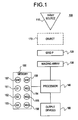
- Figure 1 shows an exemplary digital x-ray system 100 incorporating teachings of the present invention.
- system 100 includes an x-ray source 110, an x-ray focusing grid 120, an imaging array 130, a processor 140, a memory 150, and output devices 160.
- x-ray source 110 an x-ray source 110
- x-ray focusing grid 120 an imaging array 130
- processor 140 a processor 140
- memory 150 an imaging array 130
- output devices 160 for clarity, other x-ray system components such as a collimator, system controller, automatic exposure controller, and so forth are not shown.
- X-ray source 110 emits x-ray photons at one or more selectable energy levels.
- the exemplary embodiment uses any type of x-ray source, for example one with many different intensity settings. (The invention, however, is not limited to any type of x-ray source or any type, range, or number of selectable x-ray source operational criteria.)
- An object or body 170 placed between x-ray source 110 and x-ray focusing grid 120 absorbs, passes, and scatters x-ray photons based on its structure and composition.
- X-ray focusing grid 120 absorbs most scattered photons and passes most primary photons onto imaging array 130.
- Grid 120 in the exemplary embodiment, is manually or automatically movable in and out of the path of radiation from x-ray source 110. Examples of suitable grids include those described in U.S. Patents 5,581,592 and 5,291,539 . Some embodiments use a focusing grid which carries strategic markers for locating it in x-ray images, and others include not only strategic markers, but also identification markers.
- the exemplary embodiment uses one of a number of grids P, generally denoted as grid 1, grid 2, ..., grid P. These are generically indicated as grid P in Figure 1 . (With adjustable or reconfigurable grids, each possible reconfiguration constitutes a separate grid P.) Primary photons that pass through grid 120 strike imaging array 130.
- Imaging array 130 includes a two-dimensional array of sensors or detectors (not shown).
- the array is rectangular and includes K rows and L columns of detectors, with each detector (or detector pixel) having a unique address or position based on its row and column.
- imaging array 130 also includes associated signal-conditioning electronics, such as sense amplifiers and/or analog-to-digital converters, as known or will be known in the art.
- the detectors detect x-rays indirectly through light from a phosphor medium, and in others, the detectors detect x-rays directly.
- image array 130 provides a set of digital image signals, or pixel values, based on the output of the detectors to processor 140. (As used herein, image refers to a set of one or more pixel values originating, or otherwise derived through processing signals, from at least one corresponding detector in an imaging array.)
- Memory 150 includes a number of partial or modular correction maps 151-156.
- Partial correction maps 151, 152, and 153 are grid-only correction maps, that is, they are intended only to correct for grid effects in object, or application, images.
- partial correction maps 154, 155, and 156 are non-grid-correction maps, which are intended to correct the effects of one or more other system components on application images. (As used herein, map refers to array of numerical values intended for correction of an image.)
- the non-grid-correction maps correct for all other system components except for grids. However, in other embodiments, a number of distinct non-grid-correction maps correct independently for non-uniform x-ray field, x-ray beam geometry, or any other characteristics.
- Memory 150 also includes one or more software modules or computer programs 157 and 158 which respectively govern how processor 140 defines and applies each of the non-grid and grid-only correction maps. Exemplary memory devices include magnetic, optical, and electronic read-only memories, random-access-memories, and combinations of these types of devices.
- Output devices 160 include one more image displays, printers, and/or communications devices for outputting image information.
- the communications devices allow transmission of image information over telephone and broadcast communications channels as desired to facilitate remote processing or diagnosis.
- processor 140 determines identity of grid 120 by locating grid-identifying markers in the application image, by looking at operator inputs or settings, or by using Fourier transforms of the grid image and the application image. After this determination, processor 140 selects from memory 140 the appropriate combination of two or more partial-correction maps, for example, one grid-only correction map and at least one non-grid correction map, for use in correcting the application image. The processor then registers the correction maps to the application image and corrects the application image by applying the registered partial-correction maps sequentially to the application image.
- the processor mathematically combines the selected partial-correction maps into a total-correction map and then applies the total-correction map to the application image.
- the corrected application image is subject to further processing (not described here) and then transferred to output devices 160 for output in one or more desired forms.
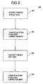
- Figure 2 and 3 respectively illustrate flow charts for exemplary methods of determining partial correction maps and then applying them to correct an application image. More particularly, Figure 2 shows an exemplary flow chart 200, illustrating operation of system 100 and especially processor 140 in accord with software modules or computer programs 157.
- Flow chart 200 includes blocks 202-208, which are executed serially or in parallel in the exemplary embodiment. Some embodiments organize the exemplary process using a greater or lesser number of blocks. Other embodiments implement the blocks as two or more specific interconnected hardware modules with related control and data signals communicated between and through the modules.
- the exemplary process flow is applicable to software, firmware, and hardware implementations. In most, if not all instances, the process sequence can be varied from the order shown and described.
- M IJ f G IJ NG IJ , where f denotes a generic functional or mathematical combination; G IJ denotes a grid-only correction pixel value for detector IJ; and NG IJ denotes a non-grid-correction pixel value used for correcting the output of detector IJ for one or more non-grid effects.
- f a generic functional or mathematical combination
- G IJ denotes a grid-only correction pixel value for detector IJ
- NG IJ denotes a non-grid-correction pixel value used for correcting the output of detector IJ for one or more non-grid effects.
- Process block 202 entails acquiring N first flat-field images without an object or patient and without x-ray focusing grid 120 being between x-ray source 110 and imaging array 130.
- Each of the N first flat-field images corresponds to a particular one of the N possible non-grid configurations of system 100.
- Prior to acquiring the first image some embodiments manually or automatically move grid 120 out of the path of radiation from x-ray source 110.
- a series of flat-field images are aggregated (with uniform or non-uniform weighting) and averaged to determine each of the N first flat-field images. Averaging the series of flat-field images reduces noise.
- Each first flat-field image includes a set of KxL pixel values Y1 n from imaging array 120, with individual pixel values denoted Y1 IJ, n , where I and J denote particular row and column indices and subscript n ranges from 1 to N, denoting the particular one of the N possible non-grid configurations associated with the first flat-field image.
- Y1 IJ, n denotes the pixel value for the first image at detector IJ
- M' IJ,n denotes the sensitivity for the detection system at detector pixel IJ in the no-grid configuration
- X1 IJ,n denotes the incident x-ray exposure at detector IJ
- OFF1 IJ,n that is, the detector offset determined immediately before or after acquisition of the first image.
- N non-grid correction maps NG 1 , NG 2 , ... NG N to memory 150.
- Some embodiments of the invention normalize each of the non-grid correction maps before storing them to memory.
- One such embodiment normalizes each pixel value based on its mean value determined from a number of aggregated flat-field images. However, some embodiments normalize based on other measures of central tendency, based on an absolute or relative quantity for all the pixel values, or based on local or regional normalization techniques. The invention, however, is not limited to any particular normalization technique.
- Execution then proceeds to process block 206, which entails acquiring P second flat-field images without an object and with one of the P possible x-ray focusing grids 120 being between x-ray source 110 and imaging array 120.
- Each second flat-field image comprises a set of pixel values Y2p, with subscript p denoting a particular one of the P possible x-ray focusing grids and with individual pixel values denoted Y2 IJ,p .
- a series of images of each grid p are aggregated (using uniform or non-uniform weighting) and averaged to determine each of the P second flat-field images.
- the partial-correction maps are ready to be used to correct appropriate application images.
- these partial correction maps are subject to regular updates using the method outlined in Figure 2 , thereby ensuring that the maps reflect a reasonably current state of the x-ray system.
- there is substantial delay for example, hours, days, weeks, or months--- between computation and storage of the partial-correction maps and their actual use in correcting application images as shown in Figure 3 .
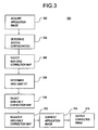
- FIG. 3 shows an exemplary flow chart 300, illustrating operation of system 100 and especially processor 140 in accord with software modules or computer programs 158. Like flow chart 200, flow chart 300 is applicable to software, firmware, and hardware implementations. Flow chart 300 includes process blocks 302-316, which can be executed serially or in parallel or reorganized as a greater or lesser number of blocks. In most, if not all instances, the process sequence can be varied from the order shown and described.
- system 100 acquires an application (patient or object) image with one of N possible system configurations and techniques defined by one or more non-grid operating criteria, such as tube and detector position, and one of P possible x-ray focusing grids placed between the x-ray source and the imaging array.
- non-grid operating criteria such as tube and detector position
- Other non-grid operating criteria which some embodiments use to define system configurations and techniques include x-ray beam energy spectrum, kVp and beam filtration, x-ray beam spatial variation source-to-image distance, x-ray collimation, x-ray tube focal spot, ion chamber characteristics, and tube, grid, and detector array alignment.
- the application image comprises a set of pixel values Y3 np , with n denoting the particular non-grid system configuration and p denoting the particular grid used in forming the application image.
- Y3 IJ, np denotes the uncorrected pixel value for the application image at detector IJ
- M IJ, np denotes the total sensitivity of the detection system at detector pixel IJ with non-grid configuration n and grid p
- X3 IJ, np denotes the incident x-ray exposure at detector IJ for the application image
- OFF3 IJ,np denotes the detector offset immediately before or after acquisition of the application image.
- each pixel value of the application image has the form M
- the processor determines the non-grid system configuration used for the application image. In the exemplary embodiment, this entails examining one or more operator inputs or corresponding x-ray system settings. Some embodiments determine the non-grid system configuration through identification of two or more parameters such as tube voltage, kVp, and focal-spot specification.
- the processor uses its determination of the non-grid system configuration to select one or more non-grid correction maps from memory.
- this entails choosing an existing non-grid correction map which was generated for the non-grid system - configuration used to form the subject application image.
- this entails selecting two or more non-grid correction maps, each one addressing a different non-grid aspect of the system configuration.
- execution of the exemplary method continues at block 308.
- Block 308 entails determining the identity or type of grid placed between the x-ray source and the imaging array and finding the identified in the application image.
- a first method is to look at x-ray system inputs or settings indicating the grid identity or type.
- a second method is to recognize identity or type markers from the grid in the application image.
- a third is to compare the distinct Fourier transforms of each of the possible grids to Fourier transforms of the application image, using signature spectrum features for discrimination.
- Finding the grid includes determining the rotation and translation of the identified grid in the application image.
- Block 310 entails using the determined grid identity or grid type to select a grid-only correction map, such as grid-only correction map P, from memory.
- block 312 entails registering the selected grid-only correction map to the application image. Registration entails orienting the grid-only correction map to the application image to ensure that its pixel correction values are applied to the correct pixels of the application image.
- the exemplary embodiment uses affine registration, Fourier spectrum analysis, or the location of visible grid features in the application image to ensure proper registration.
- Block 314 entails correcting the application image based on the one or more selected non-grid correction maps and the selected grid-only correction map.
- this entails applying partial correction maps Gp and NG n to the application image as prescribed in equation (7):
- Y ⁇ 3 ⁇ ⁇ IJ f G IJ , p NG IJ , n - 1 * Y ⁇ 3 IJ , np - OFF ⁇ 3 IJ , np , where Y3' IJ denotes the corrected pixel value for pixel value IJ of the application image;
- f(G IJ , NG IJ )] -1 denotes the total correction map as defined in equation (2); and the quantity [Y3 IJ - OFF3 IJ ] denotes the offset corrected application image pixel value IJ.
- Block 316 entails outputting the corrected image to output devices 160.
- exemplary methods and apparatus in accord with the invention facilitate the same correction capability with storage of only N+P (N plus P) different correction maps.
Landscapes
- Engineering & Computer Science (AREA)
- Health & Medical Sciences (AREA)
- Life Sciences & Earth Sciences (AREA)
- Medical Informatics (AREA)
- Radiology & Medical Imaging (AREA)
- Molecular Biology (AREA)
- Biophysics (AREA)
- High Energy & Nuclear Physics (AREA)
- Signal Processing (AREA)
- Nuclear Medicine, Radiotherapy & Molecular Imaging (AREA)
- Optics & Photonics (AREA)
- Pathology (AREA)
- Multimedia (AREA)
- Biomedical Technology (AREA)
- Heart & Thoracic Surgery (AREA)
- Physics & Mathematics (AREA)
- Surgery (AREA)
- Animal Behavior & Ethology (AREA)
- General Health & Medical Sciences (AREA)
- Public Health (AREA)
- Veterinary Medicine (AREA)
- Computer Vision & Pattern Recognition (AREA)
- Image Processing (AREA)
- Apparatus For Radiation Diagnosis (AREA)
- Image Analysis (AREA)
Applications Claiming Priority (2)
| Application Number | Priority Date | Filing Date | Title |
|---|---|---|---|
| US09/386,701 US6542575B1 (en) | 1999-08-31 | 1999-08-31 | Correction methods and apparatus for digital x-ray imaging |
| US386701 | 1999-08-31 |
Publications (3)
| Publication Number | Publication Date |
|---|---|
| EP1081947A2 EP1081947A2 (en) | 2001-03-07 |
| EP1081947A3 EP1081947A3 (en) | 2003-11-12 |
| EP1081947B1 true EP1081947B1 (en) | 2012-08-08 |
Family
ID=23526684
Family Applications (1)
| Application Number | Title | Priority Date | Filing Date |
|---|---|---|---|
| EP20000307147 Expired - Lifetime EP1081947B1 (en) | 1999-08-31 | 2000-08-21 | Correction methods and apparatus for digital x-ray imaging |
Country Status (3)
| Country | Link |
|---|---|
| US (1) | US6542575B1 (enExample) |
| EP (1) | EP1081947B1 (enExample) |
| JP (1) | JP4585665B2 (enExample) |
Families Citing this family (33)
| Publication number | Priority date | Publication date | Assignee | Title |
|---|---|---|---|---|
| KR100538659B1 (ko) * | 2001-08-13 | 2005-12-26 | 콸콤 인코포레이티드 | 컴퓨터 장치의 저장 영역에 대한 애플리케이션 레벨 액세스 특권을 부여하는 방법 및 장치 |
| US7123684B2 (en) | 2002-11-27 | 2006-10-17 | Hologic, Inc. | Full field mammography with tissue exposure control, tomosynthesis, and dynamic field of view processing |
| US10638994B2 (en) | 2002-11-27 | 2020-05-05 | Hologic, Inc. | X-ray mammography with tomosynthesis |
| US7616801B2 (en) | 2002-11-27 | 2009-11-10 | Hologic, Inc. | Image handling and display in x-ray mammography and tomosynthesis |
| DE10312450A1 (de) * | 2003-03-20 | 2004-10-07 | Siemens Ag | Verfahren zur Kompensation von Bildstörungen bei Strahlungsbildaufnahmen sowie Strahlungsbildaufnahmevorrichtung |
| JP4596748B2 (ja) * | 2003-05-07 | 2010-12-15 | キヤノン株式会社 | 放射線画像撮影装置及び放射線画像撮影装置における再構成方法 |
| DE10343787B4 (de) * | 2003-09-22 | 2006-03-16 | Siemens Ag | Verfahren zur Kalibrierung eines digitalen Röntgendetektors und zugehörige Röntgenvorrichtung |
| KR100619020B1 (ko) * | 2004-05-22 | 2006-08-31 | 삼성전자주식회사 | 광 기록 정보 저장 매체 및 기록/재생 장치 |
| US7869563B2 (en) | 2004-11-26 | 2011-01-11 | Hologic, Inc. | Integrated multi-mode mammography/tomosynthesis x-ray system and method |
| US8284208B2 (en) * | 2006-05-24 | 2012-10-09 | General Electric Company | Processes and apparatus for information transfer |
| JP5239585B2 (ja) * | 2008-07-28 | 2013-07-17 | 株式会社島津製作所 | X線撮像装置 |
| JP5908281B2 (ja) * | 2008-11-24 | 2016-04-26 | ホロジック, インコーポレイテッドHologic, Inc. | トモシンセシス及びマンモグラフィ撮像用のx線焦点特性を制御する方法及びシステム |
| US8515005B2 (en) | 2009-11-23 | 2013-08-20 | Hologic Inc. | Tomosynthesis with shifting focal spot and oscillating collimator blades |
| JP4853591B2 (ja) * | 2008-12-01 | 2012-01-11 | 株式会社島津製作所 | 放射線撮像装置 |
| DE102008062661A1 (de) | 2008-12-16 | 2010-06-17 | Otto-Von-Guericke-Universität Magdeburg Medizinische Fakultät | Verfahren und Vorrichtung zum Kalibrieren eines digitalen Röntgenstrahlendetektors |
| JP5206426B2 (ja) * | 2009-01-08 | 2013-06-12 | 株式会社島津製作所 | 放射線撮像装置 |
| US8265369B2 (en) * | 2009-04-16 | 2012-09-11 | Apteryx, Inc. | Apparatus and method for virtual flaw removal from X-ray sensitive plates |
| JP5375655B2 (ja) * | 2010-02-18 | 2013-12-25 | 株式会社島津製作所 | 放射線撮影装置 |
| JP2012070842A (ja) * | 2010-09-28 | 2012-04-12 | Fujifilm Corp | 放射線画像撮影装置および方法 |
| JP2012143549A (ja) * | 2010-12-21 | 2012-08-02 | Fujifilm Corp | 放射線画像生成方法および放射線画像撮影装置 |
| DE102011088265B4 (de) | 2011-12-12 | 2017-10-19 | Siemens Healthcare Gmbh | Verfahren zur Korrektur von aufgrund eines Streustrahlenrasters auftretenden Bildartefakten |
| JP6072096B2 (ja) | 2015-01-30 | 2017-02-01 | キヤノン株式会社 | 放射線撮影システム、制御方法、制御方法、及びプログラム |
| JP6632230B2 (ja) * | 2015-06-30 | 2020-01-22 | キヤノン株式会社 | 画像処理装置および画像処理方法、画像処理プログラム |
| JP7085492B2 (ja) | 2016-04-22 | 2022-06-16 | ホロジック,インコーポレイテッド | アドレス指定可能なアレイを使用する偏移焦点x線システムを用いるトモシンセシス |
| EP3668404B1 (en) | 2017-08-16 | 2022-07-06 | Hologic, Inc. | Techniques for breast imaging patient motion artifact compensation |
| EP3449835B1 (en) | 2017-08-22 | 2023-01-11 | Hologic, Inc. | Computed tomography system and method for imaging multiple anatomical targets |
| US11090017B2 (en) | 2018-09-13 | 2021-08-17 | Hologic, Inc. | Generating synthesized projection images for 3D breast tomosynthesis or multi-mode x-ray breast imaging |
| EP3832689A3 (en) | 2019-12-05 | 2021-08-11 | Hologic, Inc. | Systems and methods for improved x-ray tube life |
| US11471118B2 (en) | 2020-03-27 | 2022-10-18 | Hologic, Inc. | System and method for tracking x-ray tube focal spot position |
| US11786191B2 (en) | 2021-05-17 | 2023-10-17 | Hologic, Inc. | Contrast-enhanced tomosynthesis with a copper filter |
| US12039745B2 (en) | 2021-07-27 | 2024-07-16 | GE Precision Healthcare LLC | Method and systems for removing anti-scatter grid artifacts in x-ray imaging |
| JP2023056167A (ja) * | 2021-10-07 | 2023-04-19 | キヤノンメディカルシステムズ株式会社 | 骨情報測定装置、通知装置、x線診断装置、骨情報測定方法及びプログラム |
| US12414217B2 (en) | 2022-02-07 | 2025-09-09 | Hologic, Inc. | Systems and methods for adaptively controlling filament current in an X-ray tube |
Family Cites Families (22)
| Publication number | Priority date | Publication date | Assignee | Title |
|---|---|---|---|---|
| JPS60210087A (ja) * | 1984-04-03 | 1985-10-22 | Toshiba Corp | X線診断装置 |
| US4789930A (en) | 1985-11-15 | 1988-12-06 | Picker International, Inc. | Energy dependent gain correction for radiation detection |
| US4829552A (en) | 1985-12-06 | 1989-05-09 | Rossi Remo J | Anti-scatter grid system |
| JPS62176433A (ja) * | 1986-01-28 | 1987-08-03 | 株式会社島津製作所 | 散乱x線除去サブトラクシヨンシステム |
| JPS63131134A (ja) * | 1986-11-21 | 1988-06-03 | Fuji Photo Film Co Ltd | 放射線画像情報記録読取装置 |
| US4875227A (en) | 1986-12-06 | 1989-10-17 | Rossi Remo J | Anti-scatter grid system |
| JPH0740293B2 (ja) * | 1988-04-06 | 1995-05-01 | 株式会社東芝 | X線画像処理装置 |
| JPH02237277A (ja) * | 1989-03-09 | 1990-09-19 | Toshiba Corp | X線診断装置 |
| JP2754068B2 (ja) * | 1989-06-09 | 1998-05-20 | 富士写真フイルム株式会社 | 放射線画像信号生成方法および放射線画像読取装置 |
| JPH0381879A (ja) * | 1989-08-24 | 1991-04-08 | Canon Inc | 医用画像処理装置 |
| FR2671229B1 (fr) | 1990-12-28 | 1993-03-19 | Gen Electric Cgr | Procede, tube et systeme pour eliminer une grille anti-diffusante fixe dans une image radiologique. |
| JPH0582111A (ja) * | 1991-09-19 | 1993-04-02 | Matsushita Electric Ind Co Ltd | 電池パツク |
| US5291539A (en) | 1992-10-19 | 1994-03-01 | General Electric Company | Variable focussed X-ray grid |
| US5581592A (en) | 1995-03-10 | 1996-12-03 | General Electric Company | Anti-scatter X-ray grid device for medical diagnostic radiography |
| WO1997024868A1 (en) * | 1995-12-27 | 1997-07-10 | Philips Electronics N.V. | X-ray examination apparatus including an image pick-up apparatus with a correction unit |
| JP3459745B2 (ja) * | 1997-03-27 | 2003-10-27 | キヤノン株式会社 | 画像処理装置、放射線撮影装置及び画像処理方法 |
| JP4164134B2 (ja) * | 1997-05-26 | 2008-10-08 | キヤノン株式会社 | 撮像装置及び撮像方法 |
| JPH11103389A (ja) * | 1997-07-31 | 1999-04-13 | Fuji Photo Film Co Ltd | 画像情報読取方法および装置 |
| JP3277866B2 (ja) * | 1997-11-11 | 2002-04-22 | 株式会社島津製作所 | X線診断装置 |
| JP2000083951A (ja) * | 1998-09-11 | 2000-03-28 | Canon Inc | X線画像撮影装置及びグリッド装置 |
| JP3592122B2 (ja) * | 1999-01-26 | 2004-11-24 | キヤノン株式会社 | X線画像処理装置 |
| JP4822571B2 (ja) * | 1999-08-03 | 2011-11-24 | キヤノン株式会社 | デジタルx線撮影システム及び方法 |
-
1999
- 1999-08-31 US US09/386,701 patent/US6542575B1/en not_active Expired - Lifetime
-
2000
- 2000-08-21 EP EP20000307147 patent/EP1081947B1/en not_active Expired - Lifetime
- 2000-08-30 JP JP2000260021A patent/JP4585665B2/ja not_active Expired - Lifetime
Also Published As
| Publication number | Publication date |
|---|---|
| JP2001134748A (ja) | 2001-05-18 |
| US6542575B1 (en) | 2003-04-01 |
| JP4585665B2 (ja) | 2010-11-24 |
| EP1081947A3 (en) | 2003-11-12 |
| EP1081947A2 (en) | 2001-03-07 |
Similar Documents
| Publication | Publication Date | Title |
|---|---|---|
| EP1081947B1 (en) | Correction methods and apparatus for digital x-ray imaging | |
| EP0984393B1 (en) | Radiation image processing apparatus | |
| US6594339B1 (en) | X-ray examination apparatus with exposure control | |
| CN1915169B (zh) | 对用于产生3d体积图像的x-射线系统中的对准误差进行检测和校正的方法和装置 | |
| US20120014618A1 (en) | System and method for measuring x-ray beam profile using an area detector | |
| KR20010113814A (ko) | 디지털 이미징 시스템에서의 이득 보정 인자 계산 방법 | |
| US20110121163A1 (en) | Method, apparatus and computer-readable medium estimating energy response function of energy resolving x-ray detector | |
| US6460003B1 (en) | Apparatus and method for resolution calibration of radiographic images | |
| EP1423733A1 (en) | Method and apparatus for identifying and correcting line artifacts in a solid state x-ray detector | |
| JP2001508171A (ja) | 2つの順次補正マップを有するガンマ・カメラ | |
| US7218705B2 (en) | Systems, methods and apparatus to offset correction of X-ray images | |
| CN100484192C (zh) | 用于生成子图像的方法和设备 | |
| US7822173B2 (en) | Smart radiation detector module | |
| US7553081B2 (en) | X-ray system and calibration method therefor | |
| Bruijns et al. | Technical and clinical results of an experimental flat dynamic (digital) x-ray image detector (FDXD) system with real-time corrections | |
| US6198800B1 (en) | Exposure control for digital radiography systems using charge build-up in sensor array pixels | |
| EP1186910B1 (en) | Means for measuring the offset induced by photo-conductive fets in a solid state x-ray detector | |
| US5491342A (en) | Apparatus and method for nuclear camera calibration | |
| WO2019092981A1 (ja) | 画像処理装置、画像処理方法、放射線撮影装置、放射線撮影装置の制御方法、およびプログラム | |
| US6618604B2 (en) | Method and apparatus for correcting the offset induced by field effect transistor photo-conductive effects in a solid state x-ray detector | |
| CN101109820A (zh) | 确定辐射检测器的灵敏度的方法 | |
| US20070252079A1 (en) | Non-uniformity energy correction method and apparatus | |
| EP1151645B1 (en) | X-ray examination apparatus with exposure control | |
| US7949174B2 (en) | System and method for calibrating an X-ray detector | |
| JP2022019360A (ja) | 画像処理装置およびその制御方法 |
Legal Events
| Date | Code | Title | Description |
|---|---|---|---|
| PUAI | Public reference made under article 153(3) epc to a published international application that has entered the european phase |
Free format text: ORIGINAL CODE: 0009012 |
|
| AK | Designated contracting states |
Kind code of ref document: A2 Designated state(s): AT BE CH CY DE DK ES FI FR GB GR IE IT LI LU MC NL PT SE |
|
| AX | Request for extension of the european patent |
Free format text: AL;LT;LV;MK;RO;SI |
|
| RIN1 | Information on inventor provided before grant (corrected) |
Inventor name: XUE, PING Inventor name: SCHUBERT, SCOTT FORREST |
|
| PUAL | Search report despatched |
Free format text: ORIGINAL CODE: 0009013 |
|
| AK | Designated contracting states |
Kind code of ref document: A3 Designated state(s): AT BE CH CY DE DK ES FI FR GB GR IE IT LI LU MC NL PT SE |
|
| AX | Request for extension of the european patent |
Extension state: AL LT LV MK RO SI |
|
| 17P | Request for examination filed |
Effective date: 20040512 |
|
| AKX | Designation fees paid |
Designated state(s): DE FR NL |
|
| 17Q | First examination report despatched |
Effective date: 20070126 |
|
| GRAP | Despatch of communication of intention to grant a patent |
Free format text: ORIGINAL CODE: EPIDOSNIGR1 |
|
| GRAS | Grant fee paid |
Free format text: ORIGINAL CODE: EPIDOSNIGR3 |
|
| GRAA | (expected) grant |
Free format text: ORIGINAL CODE: 0009210 |
|
| AK | Designated contracting states |
Kind code of ref document: B1 Designated state(s): DE FR NL |
|
| REG | Reference to a national code |
Ref country code: DE Ref legal event code: R096 Ref document number: 60047396 Country of ref document: DE Effective date: 20121011 |
|
| REG | Reference to a national code |
Ref country code: NL Ref legal event code: VDEP Effective date: 20120808 |
|
| PG25 | Lapsed in a contracting state [announced via postgrant information from national office to epo] |
Ref country code: NL Free format text: LAPSE BECAUSE OF FAILURE TO SUBMIT A TRANSLATION OF THE DESCRIPTION OR TO PAY THE FEE WITHIN THE PRESCRIBED TIME-LIMIT Effective date: 20120808 |
|
| PLBE | No opposition filed within time limit |
Free format text: ORIGINAL CODE: 0009261 |
|
| STAA | Information on the status of an ep patent application or granted ep patent |
Free format text: STATUS: NO OPPOSITION FILED WITHIN TIME LIMIT |
|
| 26N | No opposition filed |
Effective date: 20130510 |
|
| REG | Reference to a national code |
Ref country code: DE Ref legal event code: R097 Ref document number: 60047396 Country of ref document: DE Effective date: 20130510 |
|
| PGFP | Annual fee paid to national office [announced via postgrant information from national office to epo] |
Ref country code: FR Payment date: 20140818 Year of fee payment: 15 |
|
| REG | Reference to a national code |
Ref country code: FR Ref legal event code: ST Effective date: 20160429 |
|
| PG25 | Lapsed in a contracting state [announced via postgrant information from national office to epo] |
Ref country code: FR Free format text: LAPSE BECAUSE OF NON-PAYMENT OF DUE FEES Effective date: 20150831 |
|
| PGFP | Annual fee paid to national office [announced via postgrant information from national office to epo] |
Ref country code: DE Payment date: 20170829 Year of fee payment: 18 |
|
| REG | Reference to a national code |
Ref country code: DE Ref legal event code: R119 Ref document number: 60047396 Country of ref document: DE |
|
| PG25 | Lapsed in a contracting state [announced via postgrant information from national office to epo] |
Ref country code: DE Free format text: LAPSE BECAUSE OF NON-PAYMENT OF DUE FEES Effective date: 20190301 |