EP1078804A2 - Procédé et appareil de commande d'un moteur et une transmission dans un véhicule - Google Patents
Procédé et appareil de commande d'un moteur et une transmission dans un véhicule Download PDFInfo
- Publication number
- EP1078804A2 EP1078804A2 EP00114599A EP00114599A EP1078804A2 EP 1078804 A2 EP1078804 A2 EP 1078804A2 EP 00114599 A EP00114599 A EP 00114599A EP 00114599 A EP00114599 A EP 00114599A EP 1078804 A2 EP1078804 A2 EP 1078804A2
- Authority
- EP
- European Patent Office
- Prior art keywords
- torque
- engine
- ind
- engine torque
- transmission
- Prior art date
- Legal status (The legal status is an assumption and is not a legal conclusion. Google has not performed a legal analysis and makes no representation as to the accuracy of the status listed.)
- Granted
Links
- 238000000034 method Methods 0.000 title claims abstract description 52
- 230000005540 biological transmission Effects 0.000 title claims description 88
- 230000008859 change Effects 0.000 claims abstract description 13
- 230000008569 process Effects 0.000 claims description 32
- 238000002485 combustion reaction Methods 0.000 claims description 6
- 230000001419 dependent effect Effects 0.000 claims description 3
- 238000002347 injection Methods 0.000 abstract 2
- 239000007924 injection Substances 0.000 abstract 2
- 238000010586 diagram Methods 0.000 description 13
- 230000006870 function Effects 0.000 description 12
- 230000001105 regulatory effect Effects 0.000 description 4
- 230000001360 synchronised effect Effects 0.000 description 4
- 230000000694 effects Effects 0.000 description 3
- 238000013519 translation Methods 0.000 description 3
- 230000014616 translation Effects 0.000 description 3
- 238000004364 calculation method Methods 0.000 description 2
- 230000007935 neutral effect Effects 0.000 description 2
- 230000007704 transition Effects 0.000 description 2
- 238000005299 abrasion Methods 0.000 description 1
- 230000009471 action Effects 0.000 description 1
- 238000005516 engineering process Methods 0.000 description 1
- 238000011156 evaluation Methods 0.000 description 1
- 230000001939 inductive effect Effects 0.000 description 1
- 238000004519 manufacturing process Methods 0.000 description 1
- 238000005457 optimization Methods 0.000 description 1
- 230000036314 physical performance Effects 0.000 description 1
- 238000012546 transfer Methods 0.000 description 1
Images


Classifications
-
- B—PERFORMING OPERATIONS; TRANSPORTING
- B60—VEHICLES IN GENERAL
- B60W—CONJOINT CONTROL OF VEHICLE SUB-UNITS OF DIFFERENT TYPE OR DIFFERENT FUNCTION; CONTROL SYSTEMS SPECIALLY ADAPTED FOR HYBRID VEHICLES; ROAD VEHICLE DRIVE CONTROL SYSTEMS FOR PURPOSES NOT RELATED TO THE CONTROL OF A PARTICULAR SUB-UNIT
- B60W10/00—Conjoint control of vehicle sub-units of different type or different function
- B60W10/04—Conjoint control of vehicle sub-units of different type or different function including control of propulsion units
- B60W10/06—Conjoint control of vehicle sub-units of different type or different function including control of propulsion units including control of combustion engines
-
- B—PERFORMING OPERATIONS; TRANSPORTING
- B60—VEHICLES IN GENERAL
- B60W—CONJOINT CONTROL OF VEHICLE SUB-UNITS OF DIFFERENT TYPE OR DIFFERENT FUNCTION; CONTROL SYSTEMS SPECIALLY ADAPTED FOR HYBRID VEHICLES; ROAD VEHICLE DRIVE CONTROL SYSTEMS FOR PURPOSES NOT RELATED TO THE CONTROL OF A PARTICULAR SUB-UNIT
- B60W10/00—Conjoint control of vehicle sub-units of different type or different function
- B60W10/10—Conjoint control of vehicle sub-units of different type or different function including control of change-speed gearings
- B60W10/11—Stepped gearings
-
- B—PERFORMING OPERATIONS; TRANSPORTING
- B60—VEHICLES IN GENERAL
- B60W—CONJOINT CONTROL OF VEHICLE SUB-UNITS OF DIFFERENT TYPE OR DIFFERENT FUNCTION; CONTROL SYSTEMS SPECIALLY ADAPTED FOR HYBRID VEHICLES; ROAD VEHICLE DRIVE CONTROL SYSTEMS FOR PURPOSES NOT RELATED TO THE CONTROL OF A PARTICULAR SUB-UNIT
- B60W30/00—Purposes of road vehicle drive control systems not related to the control of a particular sub-unit, e.g. of systems using conjoint control of vehicle sub-units
- B60W30/18—Propelling the vehicle
- B60W30/19—Improvement of gear change, e.g. by synchronisation or smoothing gear shift
-
- B—PERFORMING OPERATIONS; TRANSPORTING
- B60—VEHICLES IN GENERAL
- B60W—CONJOINT CONTROL OF VEHICLE SUB-UNITS OF DIFFERENT TYPE OR DIFFERENT FUNCTION; CONTROL SYSTEMS SPECIALLY ADAPTED FOR HYBRID VEHICLES; ROAD VEHICLE DRIVE CONTROL SYSTEMS FOR PURPOSES NOT RELATED TO THE CONTROL OF A PARTICULAR SUB-UNIT
- B60W50/00—Details of control systems for road vehicle drive control not related to the control of a particular sub-unit, e.g. process diagnostic or vehicle driver interfaces
- B60W2050/0001—Details of the control system
- B60W2050/0002—Automatic control, details of type of controller or control system architecture
- B60W2050/0004—In digital systems, e.g. discrete-time systems involving sampling
-
- B—PERFORMING OPERATIONS; TRANSPORTING
- B60—VEHICLES IN GENERAL
- B60W—CONJOINT CONTROL OF VEHICLE SUB-UNITS OF DIFFERENT TYPE OR DIFFERENT FUNCTION; CONTROL SYSTEMS SPECIALLY ADAPTED FOR HYBRID VEHICLES; ROAD VEHICLE DRIVE CONTROL SYSTEMS FOR PURPOSES NOT RELATED TO THE CONTROL OF A PARTICULAR SUB-UNIT
- B60W2520/00—Input parameters relating to overall vehicle dynamics
- B60W2520/10—Longitudinal speed
-
- B—PERFORMING OPERATIONS; TRANSPORTING
- B60—VEHICLES IN GENERAL
- B60W—CONJOINT CONTROL OF VEHICLE SUB-UNITS OF DIFFERENT TYPE OR DIFFERENT FUNCTION; CONTROL SYSTEMS SPECIALLY ADAPTED FOR HYBRID VEHICLES; ROAD VEHICLE DRIVE CONTROL SYSTEMS FOR PURPOSES NOT RELATED TO THE CONTROL OF A PARTICULAR SUB-UNIT
- B60W2540/00—Input parameters relating to occupants
- B60W2540/10—Accelerator pedal position
-
- B—PERFORMING OPERATIONS; TRANSPORTING
- B60—VEHICLES IN GENERAL
- B60W—CONJOINT CONTROL OF VEHICLE SUB-UNITS OF DIFFERENT TYPE OR DIFFERENT FUNCTION; CONTROL SYSTEMS SPECIALLY ADAPTED FOR HYBRID VEHICLES; ROAD VEHICLE DRIVE CONTROL SYSTEMS FOR PURPOSES NOT RELATED TO THE CONTROL OF A PARTICULAR SUB-UNIT
- B60W2710/00—Output or target parameters relating to a particular sub-units
- B60W2710/06—Combustion engines, Gas turbines
- B60W2710/0616—Position of fuel or air injector
-
- B—PERFORMING OPERATIONS; TRANSPORTING
- B60—VEHICLES IN GENERAL
- B60W—CONJOINT CONTROL OF VEHICLE SUB-UNITS OF DIFFERENT TYPE OR DIFFERENT FUNCTION; CONTROL SYSTEMS SPECIALLY ADAPTED FOR HYBRID VEHICLES; ROAD VEHICLE DRIVE CONTROL SYSTEMS FOR PURPOSES NOT RELATED TO THE CONTROL OF A PARTICULAR SUB-UNIT
- B60W2710/00—Output or target parameters relating to a particular sub-units
- B60W2710/06—Combustion engines, Gas turbines
- B60W2710/0666—Engine torque
-
- B—PERFORMING OPERATIONS; TRANSPORTING
- B60—VEHICLES IN GENERAL
- B60W—CONJOINT CONTROL OF VEHICLE SUB-UNITS OF DIFFERENT TYPE OR DIFFERENT FUNCTION; CONTROL SYSTEMS SPECIALLY ADAPTED FOR HYBRID VEHICLES; ROAD VEHICLE DRIVE CONTROL SYSTEMS FOR PURPOSES NOT RELATED TO THE CONTROL OF A PARTICULAR SUB-UNIT
- B60W2710/00—Output or target parameters relating to a particular sub-units
- B60W2710/10—Change speed gearings
- B60W2710/105—Output torque
-
- F—MECHANICAL ENGINEERING; LIGHTING; HEATING; WEAPONS; BLASTING
- F02—COMBUSTION ENGINES; HOT-GAS OR COMBUSTION-PRODUCT ENGINE PLANTS
- F02D—CONTROLLING COMBUSTION ENGINES
- F02D2200/00—Input parameters for engine control
- F02D2200/50—Input parameters for engine control said parameters being related to the vehicle or its components
- F02D2200/501—Vehicle speed
-
- F—MECHANICAL ENGINEERING; LIGHTING; HEATING; WEAPONS; BLASTING
- F02—COMBUSTION ENGINES; HOT-GAS OR COMBUSTION-PRODUCT ENGINE PLANTS
- F02D—CONTROLLING COMBUSTION ENGINES
- F02D2250/00—Engine control related to specific problems or objectives
- F02D2250/18—Control of the engine output torque
-
- F—MECHANICAL ENGINEERING; LIGHTING; HEATING; WEAPONS; BLASTING
- F16—ENGINEERING ELEMENTS AND UNITS; GENERAL MEASURES FOR PRODUCING AND MAINTAINING EFFECTIVE FUNCTIONING OF MACHINES OR INSTALLATIONS; THERMAL INSULATION IN GENERAL
- F16H—GEARING
- F16H59/00—Control inputs to control units of change-speed-, or reversing-gearings for conveying rotary motion
- F16H59/36—Inputs being a function of speed
- F16H59/46—Inputs being a function of speed dependent on a comparison between speeds
-
- F—MECHANICAL ENGINEERING; LIGHTING; HEATING; WEAPONS; BLASTING
- F16—ENGINEERING ELEMENTS AND UNITS; GENERAL MEASURES FOR PRODUCING AND MAINTAINING EFFECTIVE FUNCTIONING OF MACHINES OR INSTALLATIONS; THERMAL INSULATION IN GENERAL
- F16H—GEARING
- F16H61/00—Control functions within control units of change-speed- or reversing-gearings for conveying rotary motion ; Control of exclusively fluid gearing, friction gearing, gearings with endless flexible members or other particular types of gearing
- F16H61/04—Smoothing ratio shift
- F16H61/06—Smoothing ratio shift by controlling rate of change of fluid pressure
- F16H61/061—Smoothing ratio shift by controlling rate of change of fluid pressure using electric control means
-
- F—MECHANICAL ENGINEERING; LIGHTING; HEATING; WEAPONS; BLASTING
- F16—ENGINEERING ELEMENTS AND UNITS; GENERAL MEASURES FOR PRODUCING AND MAINTAINING EFFECTIVE FUNCTIONING OF MACHINES OR INSTALLATIONS; THERMAL INSULATION IN GENERAL
- F16H—GEARING
- F16H63/00—Control outputs from the control unit to change-speed- or reversing-gearings for conveying rotary motion or to other devices than the final output mechanism
- F16H63/40—Control outputs from the control unit to change-speed- or reversing-gearings for conveying rotary motion or to other devices than the final output mechanism comprising signals other than signals for actuating the final output mechanisms
- F16H63/50—Signals to an engine or motor
Definitions
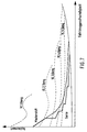
- an accelerator pedal is mechanically connected directly to the Throttle valve of a vehicle coupled so that a corresponding to the Operation of the accelerator pedal sets a certain engine torque. This will Transfer to the drive wheels according to the gear ratio.
- a stepped automatic transmission between the drive motor and the drive wheels in this embodiment result from the Gear changes resulting step-shaped course of the transmission output torque.
- DE 197 03 863 A1 describes a method and a device for control the drive train of a vehicle is known. While driving becomes a target value for the drive torque of the vehicle or specified for the transmission output torque.
- the different Operating points of the drive train are at least different output torques of the drive unit and speed ratios characterized. Then during the driving operation for possible operating points evaluation variables determined. Through an optimization process an optimal operating point is selected based on this and the associated settings made on the gearbox. Alternatively To set the gear ratio, you can also select the gear ratio selected Output speed of the drive unit belonging to the operating point a change in the gear ratio can be set.
- the aim of the present invention is to achieve such behavior even with automatic stage transmissions replicate.
- Another goal is to have any desired wheel torque or transmission output torque curve deviating from the hyperbolic form without discontinuities to realize. It is particularly noted that the wheel moments and the transmission drive torque - apart from a transmission factor - essentially correspond.
- the engine torque specifications are therefore coordinated in the form that first a synchronization motor torque M_IND_SYNC is calculated, which is the engine torque required at the time after the switching process indicates.
- M_IND_ACC acting on the filling becomes calculated at least from the synchronization engine torque and that on the ignition engine torque M_IND_GS is determined such that a predetermined and from the step change in gear when switching the transmission dependent speed curve can be adjusted. Outside the slip state the transmission output or wheel torque remains of the friction element preferably by providing the moment acting on the filling M_IND_ACC remains unaffected.
- the engine has the requested engine torque M_IND_ACC cannot provide.
- the prerequisite for this is that the engine torque that can be realized by the engine M_IND is determined by an engine model, which together with the synchronization motor torque M_IND_SYNC for calculation of the transmission output torque during switching operations and thus the friction element control variable to be set is used.
- torque coordination is possible with the above method, which it is with a multi-stage automatic transmission both during and outside of a switching process, for example one of one Accelerator pedal interpreter, hyperbolic above the vehicle speed continuously realizing transmission output torque. In this way, discontinuities in torque can be avoided and traction neutrality are essentially guaranteed.
- the engine torque acting on the filling becomes M_IND_ACC preferably at the beginning of the switching process synchronization torque value required after the shift M_IND_SYNC brought. This is at least in partial load operation sufficient during the switching process, provided by the filling Motor torque potential available.
- This engine torque can be calculated by the transmission control and sent to the engine coordinator or delivered directly to the engine control.
- the engine can actually implement it Moment smaller than the synchronous motor torque, the synchronous motor torque becomes a resulting synchronous transmission output torque is calculated and a transition function based on the transmission output torque before the circuit generates the corrected specification for the friction element control represents or control during the switching process (corrected target output torque curve).
- the reserve engine torque is used to assess whether the friction element control must be intervened.
- a Motor potential which under the given switching conditions for Compliance with the specified speed curve is not sufficient Friction element of the stepped automatic transmission set such that corrected target output torque curve is deviated and thus sets the required speed curve.
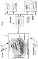
- FIG. 6 shows a schematic illustration of an embodiment of the present Invention.
- An electric accelerator pedal 110 is used accordingly generates a signal in its driving position and sends it to an accelerator pedal interpreter 112 passed on.
- Accelerator pedal interpreter 112 also receives a signal from a speed sensor 114 and generates taking this into account two signals and the relationship stored in its memory a wheel torque between these two quantities. Of course you can too other parameters are taken into account when generating the wheel torque become.
- the generated wheel torque is delivered to a torque coordinator 116, the engine torque specifications from this and taking gearbox settings into account generated, which he sent to digital engine electronics 118 (DME) passes on.
- engine torque specifications are M_IND_ACC and M_IND_GS to the DME 118, which indicate the filling and the Ignition work.
- the DME 118 generates from the engine torque specifications M_IND_ACC and M_IND_GS and others on driving operating conditions declining parameters signals for filling and ignition that then in a known manner for operating the motor (not shown in FIG. 1) to lead.
- Figure 1 is a moment structure for an embodiment of the invention Procedure shown. Here are those to be explained later Reference numerals 12, 16, 20, 22, 24 and 30 to the torque coordinator 116 assign from Fig. 6. Reference numerals 26 and 28 are the transmission side assign and the reference numerals 14 and 18 of the engine side.
- the engine coordinator 12 determines the associated engine torque quantities M_IND_GS, M_IND_SYNC and M_IND_AKT and specifies these signals units described below.
- the synchronization motor torque M_IND_SYNC is that Engine torque, which is required after the switching process.
- the unit Additional lead “16 calculates an additional engine torque potential required during the shifting process. This potential can be determined from the engine data and the transmission data and takes into account, for example, the torque that is required for the engine to start up during a downshift.
- the engine torque potential is added to the synchronization engine torque M_IND_SYNC and in the form of the engine torque specification M_IND_ACC acting on the filling to the digital engine electronics 118 (cf. also description of FIGS. 3a and 5a).
- the engine torque specification M_IND_ACC acting on the filling determines the filling in the cylinders as the desired engine torque.
- the digital engine electronics 118 From the aforementioned data, in particular from the filling data M_IND_ACC and other driving operating conditions - including the speed data N_MOT - the digital engine electronics 118 not only calculate the control information for the engine 18 but also the engine torque M_IND that can actually be implemented by the engine 18.
- This engine torque M_IND which is limited by the engine torque specification M_IND_ACC acting on the filling, becomes the units "MIN selection" 20 and Dynamic function motor "22 supplied. Their functions will be clear below.
- the "MIN selection” unit 20 also receives the synchronization motor torque M_IND_SYNC. From that of unity MIN selection "20 available values, a minimum selection is made and the result as M_IND_GETR to one unit Output torque specification "24.
- the unit Output torque specification "24 calculates a gear output torque M_AB_GETR from the quantity M_IND_GETR and passes this torque on to a function 26 close to the gearbox, which is implemented in the gearbox control 120 Additional lead "16 added engine torque does not affect the size M_IND_GETR and thus the gearbox output torque M_AB_GETR.
- the friction element (for example a clutch) is set to a transmission output torque M_AB_GETR that takes into account the lower engine torque.
- a size M_IND_GSZF is generated, which is essentially the engine torque specification acting on the ignition M_IND_GS corresponds and is passed on to the engine coordinator 12.
- the motor torque variable M_IND_GSZF can be the same M_IND_GS are transferred.
- One unity Dynamic function motor "26 represents a unit based on the motor torque M_IND that can be realized by the motor Reserve "30 an engine torque variable taking into account the time behavior of the engine (actual torque according to filling) M_IND_MOT is available.
- a torque value M_IND_AKT is also made available by the engine coordinator 12, which represents the engine torque required in accordance with the change in gear ratio during the gearshift, gearshift influences not being taken into account.
- the unit Reserve "30 calculates an existing engine torque potential M_IND_RES from the dynamic variable M_IND_MOT and the engine torque M_IND_AKT and represents this size of the unit geared function "26 available.
- the unit gear-related function "26 calculates the control or regulating data for the stepped automatic transmission or the friction elements contained therein from the data available to it.
- the quantity M_IND_GSZF influencing the ignition is also calculated from this information.
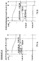
- FIG 2a is a diagram showing a shift from on during an upshift illustrates, shown, this circuit in a partial load operation takes place.
- M_IND_ACC equal to M_IND_SYNC, namely the target torque after the Switching operation.
- An additional lead torque is not necessary because the Engine reduces its speed during the switching process.
- the transmission output torques are in the lower part of the diagrams M_AB_GETR shown.
- the engine torque specification M_IND_ACC acting on the filling increases 4 at the start of switching SA in steps. That on the ignition Acting engine torque M_IND_GS is much more complex and is in the essentially determined and regulated by the transmission control 120. In particular can by changing and specifying the effect on the ignition Motor torque M_IND_GS reacted quickly and can be regulated. This leads to a largely optimal torque control during the Switching process, so that the friction elements are not excessive in their frictional performance must be charged.
- Diagram 2b shows the torque curve in a situation in which the driver's request the torque capacity of the engine (physical limit) exceeds.
- the one that acts on the filling is in advance
- Motor torque M_IND_ACC also equal to the target torque after Switching process (synchronization motor torque) M_IND_SYNC set.
- M_IND_RES negative motor torque potential
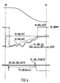
- Figures 3a and 3b and 5 are similar representation as Figures 2a and 2b and 4, respectively, show the course of the engine torques during downshifts.
- FIG. 3a shows a diagram which shows a switching sequence for a Downshift illustrates, this circuit in a partial load operation takes place.
- the synchronization engine torque M_IND_SYNC added an additional torque component (additional lead) (see Fig. 3a).
- additional lead added an additional torque component (additional lead) so that the necessary for downshifts
- the engine can be started up. This allows the engine speed also be brought into the synchronous point when downshifts. If one does not build up this additional potential, it is not sufficient Torque potential available to the speed via the ignition M_IND_GS to lead to the synchronization point. As a result, a traction neutral Output torque curve cannot be achieved.
- the unit Additional lead "16 receives from the engine coordinator 12 the synchronization engine torque variable M_IND_SYNC, which corresponds to the filling specification at the end of switching, and adds the additional provision at the beginning of the switching operation.
- the resulting filling specification M_IND_ACC (cf. FIG. 3a) is forwarded to the digital engine electronics 14 and provides this target engine torque to be set via the filling.
- Figure 5b corresponds to Figure 5a with the difference that an increase of the drive torque is desired and the motor makes such a request can also realize.
- the individual engine torque default values chosen so that at the beginning of the switching process SA an increase in the output torque is made and during of the switching process, the output torque of the transmission here desired course follows.
- the driver's request for a drive torque is greater than the physical performance of the engine allows.
Landscapes
- Engineering & Computer Science (AREA)
- Transportation (AREA)
- Mechanical Engineering (AREA)
- Chemical & Material Sciences (AREA)
- Combustion & Propulsion (AREA)
- Automation & Control Theory (AREA)
- Control Of Vehicle Engines Or Engines For Specific Uses (AREA)
- Control Of Transmission Device (AREA)
- Control Of Driving Devices And Active Controlling Of Vehicle (AREA)
Applications Claiming Priority (2)
| Application Number | Priority Date | Filing Date | Title |
|---|---|---|---|
| DE19940703 | 1999-08-27 | ||
| DE19940703A DE19940703C1 (de) | 1999-08-27 | 1999-08-27 | Verfahren und Vorrichtung zur Motor- und Getriebesteuerung bei einem Kraftfahrzeug |
Publications (3)
| Publication Number | Publication Date |
|---|---|
| EP1078804A2 true EP1078804A2 (fr) | 2001-02-28 |
| EP1078804A3 EP1078804A3 (fr) | 2004-12-15 |
| EP1078804B1 EP1078804B1 (fr) | 2007-02-28 |
Family
ID=7919819
Family Applications (1)
| Application Number | Title | Priority Date | Filing Date |
|---|---|---|---|
| EP00114599A Expired - Lifetime EP1078804B1 (fr) | 1999-08-27 | 2000-07-07 | Procédé et appareil de commande d'un moteur et une transmission dans un véhicule |
Country Status (5)
| Country | Link |
|---|---|
| US (1) | US6360154B1 (fr) |
| EP (1) | EP1078804B1 (fr) |
| JP (1) | JP2001088581A (fr) |
| DE (2) | DE19940703C1 (fr) |
| ES (1) | ES2280162T3 (fr) |
Cited By (7)
| Publication number | Priority date | Publication date | Assignee | Title |
|---|---|---|---|---|
| EP1332911A2 (fr) * | 2002-02-05 | 2003-08-06 | Volkswagen Aktiengesellschaft | Procédé de commande d'un moteur à combustion dans un véhicule |
| WO2006042630A1 (fr) * | 2004-10-20 | 2006-04-27 | Bayerische Motoren Werke Aktiengesellschaft | Systeme de commande de la vitesse longitudinale de vehicules a moteur |
| DE102011004862A1 (de) | 2011-02-28 | 2012-08-30 | Bayerische Motoren Werke Aktiengesellschaft | Bestimmen von Rad- und/oder Achsmomentvorgaben in einem Kraftfahrzeug |
| DE102011005962A1 (de) | 2011-03-23 | 2012-09-27 | Bayerische Motoren Werke Aktiengesellschaft | Aufteilen einer Momentenanforderung auf zwei von unterschiedlichen Motoren angetriebenen Antriebsachsen eines Kraftfahrzeugs |
| FR3052214A1 (fr) * | 2016-06-07 | 2017-12-08 | Peugeot Citroen Automobiles Sa | Procede d'adaptation du couple delivre par le moteur d'un vehicule, notamment automobile |
| FR3062620A1 (fr) * | 2017-02-09 | 2018-08-10 | Renault S.A.S | Procede d'elaboration de la consigne de couple aux actionneurs d'un groupe motopropulseur hybride |
| EP3789233A4 (fr) * | 2018-07-25 | 2021-06-30 | Aisin Aw Co., Ltd. | Dispositif de commande |
Families Citing this family (18)
| Publication number | Priority date | Publication date | Assignee | Title |
|---|---|---|---|---|
| JP3797096B2 (ja) * | 2000-11-29 | 2006-07-12 | 日産自動車株式会社 | 駆動力制御装置 |
| DE10225448A1 (de) * | 2002-06-08 | 2003-12-18 | Bosch Gmbh Robert | Verfahren und Vorrichtung zur Steuerung der Brennkraftmaschine eines Fahrzeugs |
| EP1535153B1 (fr) | 2002-07-29 | 2014-06-04 | Robert Bosch Gmbh | Procede de priorisation de transmetteurs d'informations, notamment pour la commande coordonnee de la chaine cinematique d'un vehicule |
| DE10244519A1 (de) * | 2002-09-25 | 2004-04-15 | Bayerische Motoren Werke Ag | Verfahren zur Regelung und/oder Steuerung einer Motor-Getriebeeinheit in einem Kraftfahrzeug |
| DE102004022114B4 (de) | 2004-05-05 | 2018-11-22 | Robert Bosch Gmbh | Verfahren zum Betreiben eines Fahrzeugs |
| FR2870793B1 (fr) * | 2004-05-28 | 2007-08-31 | Renault Sas | Dispositif de commande d'un groupe moto-propulseur de vehicule automobile permettant le controle d'un couple applique aux roues du vehicule et procede associe |
| DE102004031312A1 (de) * | 2004-06-29 | 2006-02-02 | Robert Bosch Gmbh | Verfahren zum Betreiben einer Antriebseinrichtung |
| JP4398836B2 (ja) * | 2004-09-30 | 2010-01-13 | ボッシュ株式会社 | 車両駆動制御方法及び車両駆動制御装置 |
| JP4265564B2 (ja) * | 2004-11-09 | 2009-05-20 | トヨタ自動車株式会社 | 車両およびその制御方法 |
| JP4587121B2 (ja) * | 2005-05-31 | 2010-11-24 | 株式会社デンソー | 補機付きのエンジンの制御装置 |
| US7347184B2 (en) * | 2005-11-01 | 2008-03-25 | Denso Corporation | Controller and controlling method for internal combustion engine |
| EP2202430B1 (fr) * | 2007-10-22 | 2012-05-30 | Komatsu Ltd. | Dispositif et procédé de commande de transmission pour véhicule de travail |
| US9296295B2 (en) * | 2008-12-22 | 2016-03-29 | Caterpillar Inc. | Machine control system utilizing inertial yaw sensor |
| JP6717965B2 (ja) * | 2016-10-31 | 2020-07-08 | ボッシュ株式会社 | 車両の制御装置 |
| KR20230024493A (ko) * | 2021-08-11 | 2023-02-21 | 현대자동차주식회사 | 차량의 변속 제어 장치 및 그 방법 |
| DE102022201606A1 (de) | 2022-02-16 | 2023-08-17 | Zf Friedrichshafen Ag | Verfahren zum adaptiven Festlegen eines Schaltpunkts eines Mehrgang-Lastschaltgetriebes einer Arbeitsmaschine, Steuereinrichtung, Computerprogrammprodukt, Arbeitsmaschine |
| DE102022201603A1 (de) | 2022-02-16 | 2023-08-17 | Zf Friedrichshafen Ag | Verfahren zum adaptiven Festlegen eines Schaltpunkts eines Mehrgang-Lastschaltgetriebes einer Arbeitsmaschine, Steuereinrichtung, Computerprogrammprodukt, Arbeitsmaschine |
| KR20230146281A (ko) * | 2022-04-12 | 2023-10-19 | 현대자동차주식회사 | 차량의 변속 제어 장치 및 그 방법 |
Citations (4)
| Publication number | Priority date | Publication date | Assignee | Title |
|---|---|---|---|---|
| US4893526A (en) | 1986-09-19 | 1990-01-16 | Toyota Jidosha Kabushiki Kaisha | Continuous variable transmission control system |
| DE4327906A1 (de) | 1993-08-19 | 1995-02-23 | Bayerische Motoren Werke Ag | Vorrichtung zur Reduzierung des Brennkraftmaschinenmoments bei Schaltvorgängen eines Getriebes |
| DE19626936A1 (de) | 1996-07-04 | 1998-01-15 | Tyler R | Verschleißarme und luftdichte Buchsen für Drosselklappenwellen an SU-Vergaser |
| DE19703863A1 (de) | 1997-02-03 | 1998-08-06 | Bosch Gmbh Robert | Verfahren und Vorrichtung zur Steuerung des Antriebsstrangs eines Kraftfahrzeugs |
Family Cites Families (9)
| Publication number | Priority date | Publication date | Assignee | Title |
|---|---|---|---|---|
| DE2842389C2 (de) * | 1978-09-29 | 1984-04-12 | Robert Bosch Gmbh, 7000 Stuttgart | Vorrichtung zur Einstellung des Drehmomentes einer Brennkraftmaschine |
| DE3830938A1 (de) * | 1988-09-12 | 1990-04-05 | Opel Adam Ag | Vorrichtung zur steuerung des motors und des automatikgetriebes eines kraftfahrzeugs |
| DE4309903B4 (de) * | 1992-11-19 | 2011-11-17 | Robert Bosch Gmbh | Verfahren und Vorrichtung zur Steuerung des Abtriebsmoments eines Fahrzeugantriebs |
| KR950031600A (ko) * | 1994-04-27 | 1995-12-18 | 가나이 쯔도무 | 자동변속기의 제어장치 및 제어방법 |
| DE19600915A1 (de) * | 1996-01-12 | 1997-07-17 | Zahnradfabrik Friedrichshafen | Verfahren zur Vorgabe der Übersetzung eines stufenlosen Getriebes |
| DE19709417A1 (de) * | 1996-03-14 | 1997-10-30 | Luk Getriebe Systeme Gmbh | Vorrichtung zur Ansteuerung eines Drehmomentübertragungssystems und eines Getriebes, sowie ein Verfahren hierfür |
| US6076032A (en) * | 1996-04-26 | 2000-06-13 | Honda Giken Kogyo Kabushiki Kaisha | Control system for vehicle for controlling the driving force depending on operating conditions of the vehicle |
| DE19625936A1 (de) * | 1996-06-28 | 1998-01-08 | Bosch Gmbh Robert | System zur Einstellung einer Getriebeübersetzung |
| US5980413A (en) * | 1998-08-21 | 1999-11-09 | Dana Corporation | Electronic controller for a multiple speed axle shifting apparatus |
-
1999
- 1999-08-27 DE DE19940703A patent/DE19940703C1/de not_active Expired - Lifetime
-
2000
- 2000-07-07 EP EP00114599A patent/EP1078804B1/fr not_active Expired - Lifetime
- 2000-07-07 ES ES00114599T patent/ES2280162T3/es not_active Expired - Lifetime
- 2000-07-07 DE DE50014104T patent/DE50014104D1/de not_active Expired - Lifetime
- 2000-08-21 JP JP2000249977A patent/JP2001088581A/ja active Pending
- 2000-08-28 US US09/649,219 patent/US6360154B1/en not_active Expired - Lifetime
Patent Citations (4)
| Publication number | Priority date | Publication date | Assignee | Title |
|---|---|---|---|---|
| US4893526A (en) | 1986-09-19 | 1990-01-16 | Toyota Jidosha Kabushiki Kaisha | Continuous variable transmission control system |
| DE4327906A1 (de) | 1993-08-19 | 1995-02-23 | Bayerische Motoren Werke Ag | Vorrichtung zur Reduzierung des Brennkraftmaschinenmoments bei Schaltvorgängen eines Getriebes |
| DE19626936A1 (de) | 1996-07-04 | 1998-01-15 | Tyler R | Verschleißarme und luftdichte Buchsen für Drosselklappenwellen an SU-Vergaser |
| DE19703863A1 (de) | 1997-02-03 | 1998-08-06 | Bosch Gmbh Robert | Verfahren und Vorrichtung zur Steuerung des Antriebsstrangs eines Kraftfahrzeugs |
Non-Patent Citations (1)
| Title |
|---|
| "Spezial "Antriebstechnik"", VDI-ZEITSCHRIFT NR. 134, March 1992 (1992-03-01), pages 26-49 |
Cited By (13)
| Publication number | Priority date | Publication date | Assignee | Title |
|---|---|---|---|---|
| EP1332911A2 (fr) * | 2002-02-05 | 2003-08-06 | Volkswagen Aktiengesellschaft | Procédé de commande d'un moteur à combustion dans un véhicule |
| DE10204593A1 (de) * | 2002-02-05 | 2003-08-14 | Volkswagen Ag | Verfahren zum Betreiben einer Brennkraftmaschine eines Kraftfahrzeuges |
| EP1332911A3 (fr) * | 2002-02-05 | 2006-12-06 | Volkswagen Aktiengesellschaft | Procédé de commande d'un moteur à combustion dans un véhicule |
| WO2006042630A1 (fr) * | 2004-10-20 | 2006-04-27 | Bayerische Motoren Werke Aktiengesellschaft | Systeme de commande de la vitesse longitudinale de vehicules a moteur |
| CN101044038B (zh) * | 2004-10-20 | 2010-05-26 | 宝马股份公司 | 汽车中的纵向动力控制系统 |
| WO2012116896A1 (fr) | 2011-02-28 | 2012-09-07 | Bayerische Motoren Werke Aktiengesellschaft | Détermination d'un couple aux roues et/ou d'un couple aux essieux prédéfini dans un véhicule automobile |
| DE102011004862A1 (de) | 2011-02-28 | 2012-08-30 | Bayerische Motoren Werke Aktiengesellschaft | Bestimmen von Rad- und/oder Achsmomentvorgaben in einem Kraftfahrzeug |
| DE102011005962A1 (de) | 2011-03-23 | 2012-09-27 | Bayerische Motoren Werke Aktiengesellschaft | Aufteilen einer Momentenanforderung auf zwei von unterschiedlichen Motoren angetriebenen Antriebsachsen eines Kraftfahrzeugs |
| DE102011005962B4 (de) | 2011-03-23 | 2023-07-27 | Bayerische Motoren Werke Aktiengesellschaft | Aufteilen einer Momentenanforderung auf zwei von unterschiedlichen Motoren angetriebenen Antriebsachsen eines Kraftfahrzeugs |
| FR3052214A1 (fr) * | 2016-06-07 | 2017-12-08 | Peugeot Citroen Automobiles Sa | Procede d'adaptation du couple delivre par le moteur d'un vehicule, notamment automobile |
| FR3062620A1 (fr) * | 2017-02-09 | 2018-08-10 | Renault S.A.S | Procede d'elaboration de la consigne de couple aux actionneurs d'un groupe motopropulseur hybride |
| WO2018146394A1 (fr) * | 2017-02-09 | 2018-08-16 | Renault S.A.S | Procede d'elaboration de la consigne de couple aux actionneurs d'un groupe motopropulseur hybride |
| EP3789233A4 (fr) * | 2018-07-25 | 2021-06-30 | Aisin Aw Co., Ltd. | Dispositif de commande |
Also Published As
| Publication number | Publication date |
|---|---|
| ES2280162T3 (es) | 2007-09-16 |
| EP1078804B1 (fr) | 2007-02-28 |
| DE50014104D1 (de) | 2007-04-12 |
| DE19940703C1 (de) | 2001-05-10 |
| EP1078804A3 (fr) | 2004-12-15 |
| US6360154B1 (en) | 2002-03-19 |
| JP2001088581A (ja) | 2001-04-03 |
Similar Documents
| Publication | Publication Date | Title |
|---|---|---|
| DE19940703C1 (de) | Verfahren und Vorrichtung zur Motor- und Getriebesteuerung bei einem Kraftfahrzeug | |
| EP0015907B1 (fr) | Dispositif de reglage de l'unite moteur de commande-et-transmission d'un vehicule a moteur | |
| DE4430447C2 (de) | Verfahren und Steuereinrichtung zur Steuerung des Antriebsstrangs eines Arbeitsfahrzeuges | |
| DE19631281C2 (de) | Verfahren zum Steuern des Anhaltvorgangs eines mit einem automatischen Getriebe mit stufenlos veränderbarer Übersetzung ausgerüsteten Kraftfahrzeugs | |
| DE102005013882B4 (de) | Schaltsteuereinrichtung und zugehöriges Verfahren für stufenloses Riemengetriebe | |
| DE10080639B4 (de) | Kupplungssteuervorrichtung zur automatischen Betätigung einer Kupplung während des Anfahrens | |
| DE2902632C2 (fr) | ||
| DE3636953C2 (fr) | ||
| DE4321413C2 (de) | Verfahren und Vorrichtung zur Steuerung der Antriebsleistung eines Fahrzeugs | |
| EP0956468B1 (fr) | Systeme d'evaluation de parametres de mecanismes d'entrainement et de commande de vehicules pour commander le rapport d'une transmission | |
| WO1995009741A1 (fr) | Procede permettant de moduler le couple de sortie d'une boite de vitesses automatique | |
| EP0001298A1 (fr) | Dispositif de changement de vitesse pour une transmission commandée sous charge | |
| DE19727044A1 (de) | Steuerung für den Antriebsstrang eines Kraftfahrzeugs | |
| EP0770195A2 (fr) | Procede de commande d'une transmission automatique | |
| WO1999034136A1 (fr) | Systeme de reglage du rapport de transmission d'une boite de vitesses | |
| DE112005001354T5 (de) | Auf dem Achsdrehmoment beruhendes Antriebsstrangbremsen mit Bereichswahl für eine koordinierte Drehmomentsteuerung (CTC) | |
| DE19643161A1 (de) | Steuervorrichtung für stufenlos veränderliches Getriebe | |
| DE3721605A1 (de) | Steuerungssystem fuer verbrennungsmotoren | |
| DE3628489A1 (de) | System fuer das nutzen des bremsdrehmoments eines leistungsabgabesystems mit einem getriebe mit stufenlos veraenderbarem uebersetzungsverhaeltnis zum bremsen | |
| DE10103133B4 (de) | Steuergerät eines Fahrzeuges, das mit einem Getriebe mit kontinuierlich variabler Übersetzung ausgerüstet ist, und Steuerverfahren für dieses | |
| EP1076616A2 (fr) | Commande d'ensemble transmission d'un vehicule automobile | |
| EP0633155A2 (fr) | Méthode de commande de la chaîne de propulsion de véhicules à moteur | |
| DE10225448A1 (de) | Verfahren und Vorrichtung zur Steuerung der Brennkraftmaschine eines Fahrzeugs | |
| DE19725816A1 (de) | Kraftfahrzeug, sowie ein Verfahren zur Verwendung eines Kraftfahrzeuges | |
| DE60012251T2 (de) | Antriebskraftsteuerung mit steigungsabhängigem Drehmoment Korrekturfaktor |
Legal Events
| Date | Code | Title | Description |
|---|---|---|---|
| PUAI | Public reference made under article 153(3) epc to a published international application that has entered the european phase |
Free format text: ORIGINAL CODE: 0009012 |
|
| AK | Designated contracting states |
Kind code of ref document: A2 Designated state(s): AT BE CH CY DE DK ES FI FR GB GR IE IT LI LU MC NL PT SE |
|
| AX | Request for extension of the european patent |
Free format text: AL;LT;LV;MK;RO;SI |
|
| PUAL | Search report despatched |
Free format text: ORIGINAL CODE: 0009013 |
|
| AK | Designated contracting states |
Kind code of ref document: A3 Designated state(s): AT BE CH CY DE DK ES FI FR GB GR IE IT LI LU MC NL PT SE |
|
| AX | Request for extension of the european patent |
Extension state: AL LT LV MK RO SI |
|
| 17P | Request for examination filed |
Effective date: 20050503 |
|
| AKX | Designation fees paid |
Designated state(s): AT BE CH CY DE DK ES FI FR GB GR IE IT LI LU MC NL PT SE |
|
| GRAP | Despatch of communication of intention to grant a patent |
Free format text: ORIGINAL CODE: EPIDOSNIGR1 |
|
| GRAS | Grant fee paid |
Free format text: ORIGINAL CODE: EPIDOSNIGR3 |
|
| GRAA | (expected) grant |
Free format text: ORIGINAL CODE: 0009210 |
|
| RIC1 | Information provided on ipc code assigned before grant |
Ipc: B60W 10/04 20060101AFI20070118BHEP |
|
| AK | Designated contracting states |
Kind code of ref document: B1 Designated state(s): DE ES FR GB IT SE |
|
| REG | Reference to a national code |
Ref country code: GB Ref legal event code: FG4D Free format text: NOT ENGLISH |
|
| REF | Corresponds to: |
Ref document number: 50014104 Country of ref document: DE Date of ref document: 20070412 Kind code of ref document: P |
|
| GBT | Gb: translation of ep patent filed (gb section 77(6)(a)/1977) |
Effective date: 20070412 |
|
| PG25 | Lapsed in a contracting state [announced via postgrant information from national office to epo] |
Ref country code: SE Free format text: LAPSE BECAUSE OF FAILURE TO SUBMIT A TRANSLATION OF THE DESCRIPTION OR TO PAY THE FEE WITHIN THE PRESCRIBED TIME-LIMIT Effective date: 20070531 |
|
| ET | Fr: translation filed | ||
| REG | Reference to a national code |
Ref country code: ES Ref legal event code: FG2A Ref document number: 2280162 Country of ref document: ES Kind code of ref document: T3 |
|
| PLBE | No opposition filed within time limit |
Free format text: ORIGINAL CODE: 0009261 |
|
| STAA | Information on the status of an ep patent application or granted ep patent |
Free format text: STATUS: NO OPPOSITION FILED WITHIN TIME LIMIT |
|
| 26N | No opposition filed |
Effective date: 20071129 |
|
| REG | Reference to a national code |
Ref country code: FR Ref legal event code: PLFP Year of fee payment: 16 |
|
| PGFP | Annual fee paid to national office [announced via postgrant information from national office to epo] |
Ref country code: ES Payment date: 20150619 Year of fee payment: 16 |
|
| PGFP | Annual fee paid to national office [announced via postgrant information from national office to epo] |
Ref country code: GB Payment date: 20150730 Year of fee payment: 16 Ref country code: DE Payment date: 20150711 Year of fee payment: 16 |
|
| PGFP | Annual fee paid to national office [announced via postgrant information from national office to epo] |
Ref country code: FR Payment date: 20150629 Year of fee payment: 16 |
|
| PGFP | Annual fee paid to national office [announced via postgrant information from national office to epo] |
Ref country code: IT Payment date: 20150729 Year of fee payment: 16 |
|
| REG | Reference to a national code |
Ref country code: DE Ref legal event code: R119 Ref document number: 50014104 Country of ref document: DE |
|
| GBPC | Gb: european patent ceased through non-payment of renewal fee |
Effective date: 20160707 |
|
| PG25 | Lapsed in a contracting state [announced via postgrant information from national office to epo] |
Ref country code: DE Free format text: LAPSE BECAUSE OF NON-PAYMENT OF DUE FEES Effective date: 20170201 Ref country code: FR Free format text: LAPSE BECAUSE OF NON-PAYMENT OF DUE FEES Effective date: 20160801 |
|
| REG | Reference to a national code |
Ref country code: FR Ref legal event code: ST Effective date: 20170331 |
|
| PG25 | Lapsed in a contracting state [announced via postgrant information from national office to epo] |
Ref country code: GB Free format text: LAPSE BECAUSE OF NON-PAYMENT OF DUE FEES Effective date: 20160707 |
|
| PG25 | Lapsed in a contracting state [announced via postgrant information from national office to epo] |
Ref country code: IT Free format text: LAPSE BECAUSE OF NON-PAYMENT OF DUE FEES Effective date: 20160707 |
|
| PG25 | Lapsed in a contracting state [announced via postgrant information from national office to epo] |
Ref country code: ES Free format text: LAPSE BECAUSE OF NON-PAYMENT OF DUE FEES Effective date: 20160708 |
|
| REG | Reference to a national code |
Ref country code: ES Ref legal event code: FD2A Effective date: 20181126 |