EP1078552B1 - Vorrichtung zur dynamischen anregung von plattenlautsprechern - Google Patents
Vorrichtung zur dynamischen anregung von plattenlautsprechern Download PDFInfo
- Publication number
- EP1078552B1 EP1078552B1 EP99926308A EP99926308A EP1078552B1 EP 1078552 B1 EP1078552 B1 EP 1078552B1 EP 99926308 A EP99926308 A EP 99926308A EP 99926308 A EP99926308 A EP 99926308A EP 1078552 B1 EP1078552 B1 EP 1078552B1
- Authority
- EP
- European Patent Office
- Prior art keywords
- sound panel
- driver
- sound
- panel
- core layer
- Prior art date
- Legal status (The legal status is an assumption and is not a legal conclusion. Google has not performed a legal analysis and makes no representation as to the accuracy of the status listed.)
- Expired - Lifetime
Links
Images

Classifications
-
- H—ELECTRICITY
- H04—ELECTRIC COMMUNICATION TECHNIQUE
- H04R—LOUDSPEAKERS, MICROPHONES, GRAMOPHONE PICK-UPS OR LIKE ACOUSTIC ELECTROMECHANICAL TRANSDUCERS; ELECTRIC HEARING AIDS; PUBLIC ADDRESS SYSTEMS
- H04R7/00—Diaphragms for electromechanical transducers; Cones
- H04R7/02—Diaphragms for electromechanical transducers; Cones characterised by the construction
- H04R7/04—Plane diaphragms
- H04R7/06—Plane diaphragms comprising a plurality of sections or layers
-
- H—ELECTRICITY
- H04—ELECTRIC COMMUNICATION TECHNIQUE
- H04R—LOUDSPEAKERS, MICROPHONES, GRAMOPHONE PICK-UPS OR LIKE ACOUSTIC ELECTROMECHANICAL TRANSDUCERS; ELECTRIC HEARING AIDS; PUBLIC ADDRESS SYSTEMS
- H04R7/00—Diaphragms for electromechanical transducers; Cones
- H04R7/02—Diaphragms for electromechanical transducers; Cones characterised by the construction
- H04R7/04—Plane diaphragms
- H04R7/045—Plane diaphragms using the distributed mode principle, i.e. whereby the acoustic radiation is emanated from uniformly distributed free bending wave vibration induced in a stiff panel and not from pistonic motion
-
- H—ELECTRICITY
- H04—ELECTRIC COMMUNICATION TECHNIQUE
- H04R—LOUDSPEAKERS, MICROPHONES, GRAMOPHONE PICK-UPS OR LIKE ACOUSTIC ELECTROMECHANICAL TRANSDUCERS; ELECTRIC HEARING AIDS; PUBLIC ADDRESS SYSTEMS
- H04R9/00—Transducers of moving-coil, moving-strip, or moving-wire type
- H04R9/06—Loudspeakers
- H04R9/066—Loudspeakers using the principle of inertia
Definitions
- the invention relates to a device for dynamic excitation of Record speakers according to the preamble of claim 1.
- Such devices are for example from US-A-4 514 599, WO-A-97 09859 and WO-A-98 52383 (prior art under Article 54 (3) EPC).
- Multi-resonance plates are significantly more complex because of the strong edge reflections.
- This complexity in multi-resonance plates arises from the fact that the Main lobe with frequency-dependent direction from a plurality of other such Main lobes is superimposed, so that a highly diversified directional diagram arises, which is also very frequency dependent.
- multi-resonance plates have in common that their directional diagrams tend to be on average point away from the perpendicular. This behavior causes the room is more closely involved in the projection of the sound waves.
- the sound panel is built on the sandwich principle, by two each other opposite surfaces of a very light core layer each with a thin cover layer are connected for example by gluing. So that Sound panel has good sound reproduction properties, the material for the top layer have a particularly high expansion shaft speed.
- Suitable cover layer materials are, for example, thin metal foils or also fiber-reinforced plastic films.
- the core layer There are also special requirements for the core layer. That's the way it is necessary that the usable materials have a low mass density and have low damping.
- the materials for the Core layer as high a shear modulus perpendicular to the surfaces have, which are connected to the cover layers.
- the materials usable for core layers in the direction in which later the core layer formed from this material is its largest Has a very low modulus of elasticity. This in relation at first glance contradicting the last two requirements Requirements are most likely to be met by a core layer, the one Hole structure with between the two for coating with the Breakthroughs provided with surface layers preferably has a small cross section.
- hard foams can also be used as core layer materials because despite their isotropic material properties, these are still suitable shear and have moduli of elasticity. Not to be left unmentioned in this The connection remains that when using rigid foams as material for the core layer, the cover layers have the task of doing the required produce anisotropic behavior of the sound panel.
- the invention has for its object a plate speaker or better a holder for drivers of multi-resonance plate speakers specify which are connected to the sound panel, but despite the connection with the sound panel do not or only insignificantly hinder its deformation.
- the Sound panel 11 is a section AA according to FIG. 2 through a plate loudspeaker 10 shown.
- This plate speaker 10 is essentially one Sound panel 11 and an electromagnetic driver 12 formed.
- the Sound panel 11 consists of a hard foam Core layer 11 ', which is connected to two cover layers 11 ".
- the core layer 11 can also be a Have a honeycomb structure.
- a recess 13 is milled into the sound panel 11, which houses the driver 12.
- the driver 12 is essentially one Pot-shaped yoke arrangement 14, a permanent magnet 15 and one with a voice coil 16 provided voice coil support 17 is formed.
- the Voice coil former 17 is also pot-shaped and with its Bottom 17 'connected to the core layer 11' via a plate 18.
- the Voice coil former 17 by means of a centering membrane 20 with the Inference arrangement 14 connected.
- page 21 is provided with a bracket 22.
- This bracket 22nd is provided with three tabs 23 (Fig. 2), which the lateral distance A span between the yoke arrangement 14 and the core layer 11 '.
- the holder 22 with the tabs 23 made of plastic. Unless a good one If heat dissipation from the driver 12 is desired, the holder 22 can also be used Metal be formed or be reduced to only the tabs 23.
- Fig. 3 shows a plate speaker, in which the driver 12 is not in the Sound panel 11 is integrated, but is attached to the outside of the sound panel 11.
- a holder 22 is provided to accommodate the weight of the driver 12, which has an elastic member 25 in the form of a corrugated contour.
- the holder 22 is formed all the way around and continuously connected to the sound panel 11. Which is through this continuous connection resulting stiffening of the sound panel 11 thereby diminished that the elastic member 25 in the shape of the corrugated Contour can yield to the embossed bending shafts.
- the driver 12 is also on the outside Sound panel 11 attached and connected to this by means of a bracket 22. Similar to the plate loudspeaker according to FIG. 1, the holder 22 4 also only three tabs 23, which extend from the driver 12 to the sound panel 11 guided and connected to it at points 24 (Fig. 5). As a result of that the tabs 23 have a curved contour (Fig. 4), they act at the same time as elastic members 25 and thus support the free Mobility of the sound panel 11 during operation.
- the plate loudspeaker according to FIGS. 1 and 2 is still added that the flat tabs 23 used there also with a elastic member 25 can be provided.
- This elastic member 25 can be provided, for example, in that the tabs 23 are very thin are formed and / or the distance A between the core layer 11 'and the yoke arrangement 14 is enlarged.
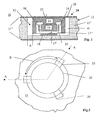
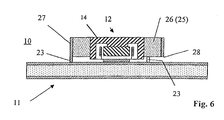
- FIG. 6 shows a section along the center line through a plate loudspeaker 10 according to the invention shown with driver 12 attached to the side.
- the bracket 22 between the Driver 12 and the sound panel 11 is solved so that the inference arrangement 14 is connected to a ring 26 made of elastic material.
- This ring 26, which acts as an elastic member 25, was in the present case made of a foam formed and is inserted into a tube 27.
- the facing the sound panel 11 The end face 28 of the tube 27 is provided with three tabs 23 (only two of which are visible in FIG. 6) are provided, which establish the connection to the sound panel 11. at In this embodiment, the decoupled connection between the driver 12 and the sound panel 11 by a combination of an elastic member 25 and an attachment reduced to three (connection) points 24.
- modifications of the shown Brackets 22 are possible. For example, it is possible to mount the bracket 22 4 and 6 so that they change one in the sound panel 11 according to FIGS Fig 1 integrated driver 12 attached.
Landscapes
- Engineering & Computer Science (AREA)
- Physics & Mathematics (AREA)
- Acoustics & Sound (AREA)
- Signal Processing (AREA)
- Multimedia (AREA)
- Diaphragms For Electromechanical Transducers (AREA)
- Audible-Bandwidth Dynamoelectric Transducers Other Than Pickups (AREA)
Description
- Fig. 1
- einen Schnitt durch einen Plattenlautsprecher;
- Fig. 2
- eine Draufsicht auf einen Plattenlautsprecher ;
- Fig. 3
- einen Schnitt durch einen Plattenlautsprecher;
- Fig. 4
- einen Schnitt durch einen weiteren Plattenlautsprecher;
- Fig. 5
- eine Draufsicht auf einen Plattenlautsprecher gemäß Fig. 4; und
- Fig. 6
- eine erfindungsgemäße Ausführungsform im Schnitt.
Claims (4)
- Vorrichtung zur dynamischen Anregung von Plattenlautsprechern mit
einem Klangpaneel (11), das eine Kernschicht (11') und mindestens eine Deckschicht (11'') umfaßt,
mindestens einem elektromagnetischen Treiber (12), der ein Magnetsystem aufweist, und
einer Halterung (22), die den Treiber (12) mit dem Klangpaneel (11) verbindet,
wobei als Halterung (22) des jeweiligen Treibers (12) ein Ring (26) aus elastischem Material vorgesehen ist, der konzentrisch das Magnetsystem umgibt und mit diesem verbunden ist, dadurch gekennzeichnet, daß
der Ring (26) in einem Rohr (27) angeordnet und mit diesem verbunden ist, wobei die dem Klangpaneel (11) zugewandte Stirnseite (28) des Rohrs (27) anhand von drei Laschen (23) mit dem Klangpaneel (11) verbunden ist. - Vorrichtung nach Anspruch 1, dadurch gekennzeichnet, daß
der Treiber (12) an das Klangpaneel (11) angesetzt ist. - Vorrichtung nach einem der Ansprüche 1 oder 2, dadurch gekennzeichnet, daß
als elastisches Material Schaumstoff vorgesehen ist. - Vorrichtung nach einem der Ansprüche 1 bis 3, dadurch gekennzeichnet, daß
der Ring (26) über seine ganze Innenseite mit dem Magnetsystem und über seine ganze Außenseite mit dem Rohr (27) verbunden ist.
Applications Claiming Priority (3)
| Application Number | Priority Date | Filing Date | Title |
|---|---|---|---|
| DE19821861 | 1998-05-15 | ||
| DE19821861A DE19821861A1 (de) | 1998-05-15 | 1998-05-15 | Vorrichtung zur dynamischen Anregung von Plattenlautsprechern |
| PCT/EP1999/003309 WO1999060817A1 (de) | 1998-05-15 | 1999-05-14 | Vorrichtung zur dynamischen anregung von plattenlautsprechern |
Publications (2)
| Publication Number | Publication Date |
|---|---|
| EP1078552A1 EP1078552A1 (de) | 2001-02-28 |
| EP1078552B1 true EP1078552B1 (de) | 2003-03-05 |
Family
ID=7867904
Family Applications (1)
| Application Number | Title | Priority Date | Filing Date |
|---|---|---|---|
| EP99926308A Expired - Lifetime EP1078552B1 (de) | 1998-05-15 | 1999-05-14 | Vorrichtung zur dynamischen anregung von plattenlautsprechern |
Country Status (4)
| Country | Link |
|---|---|
| US (1) | US6494289B1 (de) |
| EP (1) | EP1078552B1 (de) |
| DE (2) | DE19821861A1 (de) |
| WO (1) | WO1999060817A1 (de) |
Families Citing this family (17)
| Publication number | Priority date | Publication date | Assignee | Title |
|---|---|---|---|---|
| DE19821855A1 (de) | 1998-05-15 | 1999-11-18 | Nokia Deutschland Gmbh | Plattenlautsprecher |
| DE19821862A1 (de) | 1998-05-15 | 1999-11-18 | Nokia Deutschland Gmbh | Schallwiedergabeanordnung |
| DE19825866A1 (de) | 1998-06-10 | 1999-12-16 | Nokia Deutschland Gmbh | Plattenlautsprecher |
| GB2360665B (en) * | 1998-06-22 | 2003-01-15 | Slab Technology Ltd | Loudspeakers |
| DE19843079A1 (de) | 1998-09-19 | 2000-03-23 | Nokia Deutschland Gmbh | Multiresonanzplatte |
| DE10001410C2 (de) * | 2000-01-14 | 2001-12-06 | Harman Audio Electronic Sys | Flachlautsprecheranordnung |
| GB0314007D0 (en) * | 2003-06-17 | 2003-07-23 | Harris Hynd Ltd | Audio transducer |
| WO2005002926A1 (de) * | 2003-07-01 | 2005-01-13 | Johnson Controls Gmbh | Ausstattungsteil für ein fahrzeug, insbesondere ein kraftfahrzeug und verwendung eines ausstattungsteils als lautsprecher |
| EP1757161B1 (de) * | 2004-05-14 | 2016-11-30 | Sonion Nederland B.V. | Elektroakustischer wandler mit doppelter membran |
| KR101219041B1 (ko) * | 2005-07-07 | 2013-01-07 | 삼성디스플레이 주식회사 | 박막 트랜지스터 표시판 및 그 제조 방법 |
| US8204266B2 (en) | 2005-10-21 | 2012-06-19 | Sfx Technologies Limited | Audio devices |
| US7530425B2 (en) * | 2006-06-08 | 2009-05-12 | Whitaker Scott R | Speaker enclosure for a ceiling or wall mounted speaker method and apparatus |
| US20150304745A1 (en) * | 2012-03-16 | 2015-10-22 | Nokia Corporation | A sound producing vibrating surface |
| US9154862B2 (en) * | 2013-06-27 | 2015-10-06 | The Boeing Company | Flat panel loudspeaker system |
| US9014413B2 (en) | 2013-08-21 | 2015-04-21 | The Boeing Company | Dual coil loudspeaker system |
| US10848874B2 (en) * | 2018-02-20 | 2020-11-24 | Google Llc | Panel audio loudspeaker electromagnetic actuator |
| US10841704B2 (en) | 2018-04-06 | 2020-11-17 | Google Llc | Distributed mode loudspeaker electromagnetic actuator with axially and radially magnetized circuit |
Family Cites Families (12)
| Publication number | Priority date | Publication date | Assignee | Title |
|---|---|---|---|---|
| US3720285A (en) * | 1970-06-30 | 1973-03-13 | Rand Org Ltd | Loudspeakers |
| JPS603277B2 (ja) * | 1978-06-15 | 1985-01-26 | ソニー株式会社 | スピーカ装置 |
| JPS5568795A (en) * | 1978-11-20 | 1980-05-23 | Sony Corp | Speaker |
| DE3172790D1 (en) * | 1980-12-19 | 1985-12-05 | Nissan Motor | Speaker for automotive vehicle audio system |
| US4506759A (en) * | 1983-06-20 | 1985-03-26 | Northern Telecom Limited | Loudspeaker enclosure arrangement for voice communication terminals |
| US4899390A (en) * | 1986-09-19 | 1990-02-06 | Matsushita Electric Industrial Co., Ltd. | Thin speaker having an enclosure within an open portion and a closed portion |
| DE3811052C1 (de) * | 1988-03-31 | 1989-08-24 | Messerschmitt-Boelkow-Blohm Gmbh, 8012 Ottobrunn, De | |
| JP3542136B2 (ja) * | 1995-09-02 | 2004-07-14 | ニュー トランスデューサーズ リミテッド | 慣性振動トランスジューサ |
| US6192136B1 (en) * | 1995-09-02 | 2001-02-20 | New Transducers Limited | Inertial vibration transducers |
| AU703061B2 (en) * | 1995-09-02 | 1999-03-11 | New Transducers Limited | Vibration transducers |
| GB9709438D0 (en) * | 1997-05-10 | 1997-07-02 | New Transducers Ltd | Loudspeaker transducer |
| US6229903B1 (en) * | 1999-06-14 | 2001-05-08 | Citizen Electronics Co., Ltd. | Mounting structure for electromagnetic sound generator |
-
1998
- 1998-05-15 DE DE19821861A patent/DE19821861A1/de not_active Ceased
-
1999
- 1999-05-14 DE DE59904458T patent/DE59904458D1/de not_active Expired - Lifetime
- 1999-05-14 WO PCT/EP1999/003309 patent/WO1999060817A1/de not_active Ceased
- 1999-05-14 US US09/700,351 patent/US6494289B1/en not_active Expired - Lifetime
- 1999-05-14 EP EP99926308A patent/EP1078552B1/de not_active Expired - Lifetime
Also Published As
| Publication number | Publication date |
|---|---|
| US6494289B1 (en) | 2002-12-17 |
| DE59904458D1 (de) | 2003-04-10 |
| DE19821861A1 (de) | 1999-11-18 |
| EP1078552A1 (de) | 2001-02-28 |
| WO1999060817A1 (de) | 1999-11-25 |
Similar Documents
| Publication | Publication Date | Title |
|---|---|---|
| EP1078552B1 (de) | Vorrichtung zur dynamischen anregung von plattenlautsprechern | |
| DE19757098C2 (de) | Aufhängung für Schallwiedergabeanordnungen nach dem Biegewellenprinzip | |
| DE69602203T2 (de) | Paneelförmige lautsprecher | |
| DE69602101T2 (de) | Inertial-schwingungswandler | |
| EP0924959B1 (de) | Schallwiedergabeanordnung | |
| DE69601725T2 (de) | Lautsprecher mit paneelförmigen akustischen abstrahlelementen | |
| DE69602102T2 (de) | Inertial schwingungswandler | |
| DE69601734T2 (de) | Schwingungswandler | |
| EP1077014B1 (de) | FLACHES KLANGPANEEL mit Treiber | |
| DE69602204T2 (de) | PANEELFöRMIGE MIKROFONE | |
| DE69602279T2 (de) | Lautsprecher mit paneelförmigen akustischen abstrahlelementen | |
| DE2924204A1 (de) | Lautsprecher und verfahren zu dessen herstellung | |
| EP1078551B1 (de) | Plattenlautsprecher | |
| EP1078553B1 (de) | Schallwiedergabeanordnung nach dem biegewellenprinzip | |
| DE69637460T2 (de) | Lautsprecher mit Mehrpunktantrieb | |
| EP1086606B1 (de) | Plattenlautsprecher | |
| DE19840375C2 (de) | Schallwand | |
| DE10025460B4 (de) | Hochtonlautsprecher | |
| DE60004678T2 (de) | Biegewellen-plattenlautsprecher und verfahren zum betreiben desselben | |
| DE4335087B4 (de) | Verfahren und Wandler zum Wandeln der mechanischen Schwingung eines Treibers in ein akustisches Signal | |
| DE19747955C2 (de) | Lautsprecher | |
| DE19806509B4 (de) | Gerät zur Informationswiedergabe | |
| WO2000002415A1 (de) | Lautsprecher |
Legal Events
| Date | Code | Title | Description |
|---|---|---|---|
| PUAI | Public reference made under article 153(3) epc to a published international application that has entered the european phase |
Free format text: ORIGINAL CODE: 0009012 |
|
| 17P | Request for examination filed |
Effective date: 20001114 |
|
| AK | Designated contracting states |
Kind code of ref document: A1 Designated state(s): DE FR GB IT NL SE |
|
| RIN1 | Information on inventor provided before grant (corrected) |
Inventor name: REGL, HANS-JUERGEN Inventor name: KRUMP, GERHARD Inventor name: BACHMANN, WOLFGANG |
|
| 17Q | First examination report despatched |
Effective date: 20010702 |
|
| GRAH | Despatch of communication of intention to grant a patent |
Free format text: ORIGINAL CODE: EPIDOS IGRA |
|
| GRAH | Despatch of communication of intention to grant a patent |
Free format text: ORIGINAL CODE: EPIDOS IGRA |
|
| GRAA | (expected) grant |
Free format text: ORIGINAL CODE: 0009210 |
|
| AK | Designated contracting states |
Designated state(s): DE FR GB IT NL SE |
|
| PG25 | Lapsed in a contracting state [announced via postgrant information from national office to epo] |
Ref country code: NL Free format text: LAPSE BECAUSE OF FAILURE TO SUBMIT A TRANSLATION OF THE DESCRIPTION OR TO PAY THE FEE WITHIN THE PRESCRIBED TIME-LIMIT Effective date: 20030305 Ref country code: IT Free format text: LAPSE BECAUSE OF FAILURE TO SUBMIT A TRANSLATION OF THE DESCRIPTION OR TO PAY THE FEE WITHIN THE PRE;WARNING: LAPSES OF ITALIAN PATENTS WITH EFFECTIVE DATE BEFORE 2007 MAY HAVE OCCURRED AT ANY TIME BEFORE 2007. THE CORRECT EFFECTIVE DATE MAY BE DIFFERENT FROM THE ONE RECORDED.SCRIBED TIME-LIMIT Effective date: 20030305 |
|
| REG | Reference to a national code |
Ref country code: GB Ref legal event code: FG4D Free format text: NOT ENGLISH |
|
| REF | Corresponds to: |
Ref document number: 59904458 Country of ref document: DE Date of ref document: 20030410 Kind code of ref document: P |
|
| PGFP | Annual fee paid to national office [announced via postgrant information from national office to epo] |
Ref country code: NL Payment date: 20030423 Year of fee payment: 5 |
|
| PG25 | Lapsed in a contracting state [announced via postgrant information from national office to epo] |
Ref country code: SE Free format text: LAPSE BECAUSE OF FAILURE TO SUBMIT A TRANSLATION OF THE DESCRIPTION OR TO PAY THE FEE WITHIN THE PRESCRIBED TIME-LIMIT Effective date: 20030605 |
|
| GBT | Gb: translation of ep patent filed (gb section 77(6)(a)/1977) | ||
| NLV1 | Nl: lapsed or annulled due to failure to fulfill the requirements of art. 29p and 29m of the patents act | ||
| ET | Fr: translation filed | ||
| PLBE | No opposition filed within time limit |
Free format text: ORIGINAL CODE: 0009261 |
|
| STAA | Information on the status of an ep patent application or granted ep patent |
Free format text: STATUS: NO OPPOSITION FILED WITHIN TIME LIMIT |
|
| 26N | No opposition filed |
Effective date: 20031208 |
|
| REG | Reference to a national code |
Ref country code: FR Ref legal event code: PLFP Year of fee payment: 17 |
|
| PGFP | Annual fee paid to national office [announced via postgrant information from national office to epo] |
Ref country code: GB Payment date: 20150527 Year of fee payment: 17 Ref country code: DE Payment date: 20150528 Year of fee payment: 17 |
|
| PGFP | Annual fee paid to national office [announced via postgrant information from national office to epo] |
Ref country code: FR Payment date: 20150519 Year of fee payment: 17 |
|
| REG | Reference to a national code |
Ref country code: DE Ref legal event code: R119 Ref document number: 59904458 Country of ref document: DE |
|
| GBPC | Gb: european patent ceased through non-payment of renewal fee |
Effective date: 20160514 |
|
| REG | Reference to a national code |
Ref country code: FR Ref legal event code: ST Effective date: 20170131 |
|
| PG25 | Lapsed in a contracting state [announced via postgrant information from national office to epo] |
Ref country code: FR Free format text: LAPSE BECAUSE OF NON-PAYMENT OF DUE FEES Effective date: 20160531 Ref country code: DE Free format text: LAPSE BECAUSE OF NON-PAYMENT OF DUE FEES Effective date: 20161201 |
|
| PG25 | Lapsed in a contracting state [announced via postgrant information from national office to epo] |
Ref country code: GB Free format text: LAPSE BECAUSE OF NON-PAYMENT OF DUE FEES Effective date: 20160514 |