EP1077657B1 - Vorrichtung zum falten einer intraokularen linse - Google Patents
Vorrichtung zum falten einer intraokularen linse Download PDFInfo
- Publication number
- EP1077657B1 EP1077657B1 EP99915857A EP99915857A EP1077657B1 EP 1077657 B1 EP1077657 B1 EP 1077657B1 EP 99915857 A EP99915857 A EP 99915857A EP 99915857 A EP99915857 A EP 99915857A EP 1077657 B1 EP1077657 B1 EP 1077657B1
- Authority
- EP
- European Patent Office
- Prior art keywords
- mobile
- lens
- folding
- bending support
- actuation
- Prior art date
- Legal status (The legal status is an assumption and is not a legal conclusion. Google has not performed a legal analysis and makes no representation as to the accuracy of the status listed.)
- Expired - Lifetime
Links
Images


Classifications
-
- A—HUMAN NECESSITIES
- A61—MEDICAL OR VETERINARY SCIENCE; HYGIENE
- A61F—FILTERS IMPLANTABLE INTO BLOOD VESSELS; PROSTHESES; DEVICES PROVIDING PATENCY TO, OR PREVENTING COLLAPSING OF, TUBULAR STRUCTURES OF THE BODY, e.g. STENTS; ORTHOPAEDIC, NURSING OR CONTRACEPTIVE DEVICES; FOMENTATION; TREATMENT OR PROTECTION OF EYES OR EARS; BANDAGES, DRESSINGS OR ABSORBENT PADS; FIRST-AID KITS
- A61F2/00—Filters implantable into blood vessels; Prostheses, i.e. artificial substitutes or replacements for parts of the body; Appliances for connecting them with the body; Devices providing patency to, or preventing collapsing of, tubular structures of the body, e.g. stents
- A61F2/02—Prostheses implantable into the body
- A61F2/14—Eye parts, e.g. lenses, corneal implants; Implanting instruments specially adapted therefor; Artificial eyes
- A61F2/16—Intraocular lenses
- A61F2/1691—Packages or dispensers for intraocular lenses
-
- A—HUMAN NECESSITIES
- A61—MEDICAL OR VETERINARY SCIENCE; HYGIENE
- A61F—FILTERS IMPLANTABLE INTO BLOOD VESSELS; PROSTHESES; DEVICES PROVIDING PATENCY TO, OR PREVENTING COLLAPSING OF, TUBULAR STRUCTURES OF THE BODY, e.g. STENTS; ORTHOPAEDIC, NURSING OR CONTRACEPTIVE DEVICES; FOMENTATION; TREATMENT OR PROTECTION OF EYES OR EARS; BANDAGES, DRESSINGS OR ABSORBENT PADS; FIRST-AID KITS
- A61F2/00—Filters implantable into blood vessels; Prostheses, i.e. artificial substitutes or replacements for parts of the body; Appliances for connecting them with the body; Devices providing patency to, or preventing collapsing of, tubular structures of the body, e.g. stents
- A61F2/02—Prostheses implantable into the body
- A61F2/14—Eye parts, e.g. lenses, corneal implants; Implanting instruments specially adapted therefor; Artificial eyes
- A61F2/16—Intraocular lenses
- A61F2/1662—Instruments for inserting intraocular lenses into the eye
- A61F2/1664—Instruments for inserting intraocular lenses into the eye for manual insertion during surgery, e.g. forceps-like instruments
Definitions
- the invention relates to a device for folding a lens. intraocular with flexible optical part before implantation in the folded state by passage through a small incision (conventionally from 3 to 4 mm) formed in the eye (usually in the cornea).
- Intraocular lenses with flexible optical part have the advantage of being able to be folded before being introduced into the eye, this which allows them to pass through a small incision. After the implementation placed in the eye, the optical part unfolds and resumes its initial shape.
- Intraocular lenses that can be folded have a optical part made of a flexible material which can be chosen in particular from polyurethane elastomers, silicone elastomers, synthetic gels or organic (hydrated hydrogel, PMMA and / or HEMA ).
- the intraocular lenses also have a part haptic attachment to the inner wall of the eye which can either be formed of the same material that the optical part, on the contrary is formed of haptic loops in a other material, for example PMMA, attached to the optical part.
- Certain intraocular lenses with flexible optical part can be folded, at the surgeon's choice, according to one or other of several separate fold lines, chosen in particular according to the shape of the lens, its site or its mode of implantation, or the habit of surgeon.
- intraocular lenses comprising two handles haptic curves called "C" can be folded globally according to one or the other of two folding modes.
- the part optic is folded along a diametrical fold line whose extensions beyond of the optical part cut the free end part of each handle haptic.
- the lens Once the lens is folded, it presents the two handles haptics that extend longitudinally opposite each other from the part folded optics.
- the implementation is then carried out in two stages. In first step, the surgeon holding pliers between the jaws of which the part folded optic is tight, introduces the first haptic loop then the part optic in the eye (in the capsular bag for a cataract operation), then loosens the clamp to release the optical part. In a second step, the surgeon squeezes the second haptic loop which still extends to through the incision, and introduces it into the eye.
- This first folding method has the advantage of being relatively easy to execute. But it requires two stages of implantation and two passes of the forceps through the incision. The operation is therefore relatively long, and these repeated passages through the incision are a risk factor for the patient.
- the part optic is folded along a diametrical fold line whose extensions beyond of the optical part do not cut the haptic handles.
- the lens folded it presents the two haptic handles which overlap and intersect, on the same side of the folded optical part.
- the implantation can then be carried out in a single step, by first introducing the free ends of the two handles haptics, then, after a rotation, the optical part, through the incision.
- US-5,290,293 describes a one-piece folding pliers comprising implant receiving housings, and a pair of folding which approximate substantially in translation in a direction diametral of the lens when actuating connected operating handles between them by a flexible portion forming a hinge.
- the lens intraocular once placed in the receptacles can not be folded that along a single fold line perpendicular to said diametrical direction, only according to the folding mode from 6 am to 12 noon.
- the lens must first be manipulated to be placed in the receiving housing of the clamp for folding.
- US-5 139 501 describes a folding device comprising a fixed folding span on a frame, and a folding span formed at the end of a slide mounted movable in translation relative to the frame, with studs attachment of haptic loops.
- This device allows folding only according to the folding mode 3h-9h.
- the slide is guided in translation towards the lens in a dovetail slide, so that the any wear dust resulting from the friction of the parts during this displacement tend to be carried towards the lens, with the risk of dirtying it before implantation.
- folding devices have had little success commercial. Indeed, when they are offered in conjunction with the lens (for example example as packaging of the lens placed in the device in the factory), the surgeon can only use the lens with the folding mode of the corresponding folding. It is therefore necessary either to provide, before the purchase, the mode folding retained, which is rarely possible, either to build up stocks with each type of folding device. In addition, if the folding device is offered independently of the lens, risky manipulations are necessary to place the lens in the bending device, which increases the time required for the operation and the risk of soiling and deterioration of the lens.
- US-5,281,227 describes a lens folding device flexible comprising a frame, a monodirectional folding member comprising a pair of folding jaws carried by flexible elastic beams of this type folding member rotatably mounted on the frame and separable from the frame, and a cover.
- a monodirectional folding member comprising a pair of folding jaws carried by flexible elastic beams of this type folding member rotatably mounted on the frame and separable from the frame
- a cover For bend the lens in place between the jaws of the folding member, remove the cover, then the folding member is placed in the desired orientation by pivoting by compared to the frame, the frame preventing the lens from pivoting on its support, then we dissociates the folding member from the frame, the lens remaining in place between the jaws of the folding organ, then insert a gripper for gripping the lens between the jaws of the folding organ, then the two jaws are brought together, one towards the other by elastic deformation of the side members.
- This device presents in particular the disadvantage of requiring a sliding of the lens support of the organ folding with respect to the lens during the pivoting of orientation of the folding member, at the risk of deteriorating the surface condition of the optical part, particularly sensitive, from the lens.
- the folding of the lens requires a large number of manipulations, some of which are relatively delicate, on the part of the surgeon.
- the lens may fall down and be permanently lost.
- the surgeon cannot leave the folding member in an intermediate folding position taking into account the elasticity of the side members.
- the action of the surgeon on the side rails is found directly, without any reduction, on the folding jaws and on the lens so that folding cannot be done gradually and precisely. The quality of the folding is therefore closely linked to the skill of the surgeon.
- the invention therefore aims to overcome these drawbacks by proposing a device for folding an intraocular lens which allows, without prior manipulation of the lens relative to the device, to bend the lens according to one or other of several folding modes corresponding to lines of separate diametral folding, at the choice of the surgeon immediately before the implantation operation.
- the invention thus aims in particular to propose a device of folding which allows the folding of an intraocular lens with handles haptics in C, at the surgeon's choice immediately before the operation implantation, without prior manipulation of the lens relative to the device, either according to a 6 am to 12 noon folding mode, or according to a 3 am to 9 am folding mode.
- the invention also aims to propose such a device for folding that is simple and inexpensive.
- the invention aims more particularly to propose embodiments of such a folding device in which it is made a minimum number of separate pieces, including at most four pieces movable relative to each other.
- the invention also aims, and more particularly, to propose embodiments of such a folding device which present risks limited soiling and deterioration of the lens during folding.
- the invention also aims, and more particularly, to propose embodiments of such a folding device which are simple to use and immediately understandable, in particular which allow to choose the mode of folds easily, quickly, and without risk of error.
- the invention also aims, and more particularly, to propose embodiments of such a folding device which is easy to maneuver and fast, and with which folding can be performed gradually, slowly and precisely without requiring any special skill on the part of the surgeon.
- the invention aims more particularly to propose embodiments of such a folding device in which the movement imparted by the surgeon on each movable operating member is multiplied, the stroke of displacement of the corresponding movable folding span being reduced by compared to that of the mobile operating member.
- the invention also aims, and more particularly, to propose embodiments of such a folding device in which it can be used packaging of the intraocular lens and be sterilized.
- the intraocular lens is of the type comprising two haptic loops in C
- curved haptic handles flexibly deformable connected to the periphery of the optical part by one of their ends and having another free end, the two handles being globally symmetrical to each other with respect to the optical axis of the optical part
- the first diametrical direction and the second direction diametral form an angle between them between 60 ° and 120 °, so that the lens can be folded in either of two fold lines forming between them an angle between 60 ° and 120 °.
- the folding device is characterized in that the operating means comprise at least two mobile operating members, one of which is connected to at least a first movable folding span of a first pair of spans folding, and the other of which is connected to at least one second folding span mobile of a second pair of folding staves.
- the folding device is characterized in that the means for maneuver comprises a mobile maneuvering member connected to at least one first mobile folding span of the first pair of folding staves and at minus a second movable folding span of the second pair of spans of folding, this movable operating member being adapted to be able to be actuated either according to the first mode of actuation, or according to the second mode actuating.
- the device for folding is characterized in that the movable operating member is rotatably mounted with respect to the frame, in that the first actuation mode corresponds to a rotational movement of the movable operating member in a first direction rotation, and in that the second actuation mode corresponds to a rotational movement of the movable operating member in the second direction opposite to the first direction of rotation.
- the folding device is characterized in that the movable maneuvering member is mounted relative to the frame so that it can be moved in at least two separate translation directions, one of which corresponds to the first mode actuation while the other corresponds to the second actuation mode.
- the folding device is characterized in that the movable operating member is mounted relative to the frame so as to be able to be moved in at least one direction of translation and according to minus two opposite directions in this direction of translation, one of which corresponds to the first actuation mode while the other corresponds to second actuation mode.
- organ maneuvering mobile is mounted rotatable and sliding, that is to say with displacement components combined in rotation and translation.
- the folding device is characterized in that a first movable folding span of the first pair of folding spans and a second movable folding span of the second pair of folding spans are integral with one and the same intermediate moving part mounted and guided relative to the frame and connected to the movable operating member so as to be able to be driven on the move under the effect of the actuation of this movable operating member according to one or the other of the actuation modes
- a mobile operating member is connected to each mobile folding span, the movements of which it controls through a contact cam and slide system. So the actuation movement of the practitioner on this movable operating member may have a greater stroke than that of the displacement of the range of mobile folding.
- each pair of folding spans includes a fixed folding span relative to the frame.
- each scope of movable folding is mounted relative to the frame, so that it can be movable less substantially in translation, in particular in a diametrical direction corresponding.
- the device of folding is characterized in that the receiving means are adapted to receive the oriented intraocular lens, in particular relative to the frame, according to one and only one direction possible.
- the means of reception advantageously and according to the invention, include housing for receiving the haptic part of the lens -in particular haptic handles in C-.
- the receiving means can be formed, in whole or in part, by the scopes folding themselves (fixed (s) or mobile (s)).
- the lens being in place in the means of reception according to his predetermined orientation, the surgeon does not have to manipulate the lens, with pliers or otherwise, to choose the mode of folding. It suffices for him to activate the operating means of the folding according to the actuation mode appropriate to the selected folding.
- the folding device is characterized in that it constitutes a package of a lens intraocular and includes a cover closed over the lens in place in the receiving means, this cover being adapted to be able to be opened for allow access to the lens.
- this cover is adapted to also have the function of holding the lens in place in the reception means perpendicular to the plane of the optical part, that is to say along the optical axis.
- the cover is suitable for, in the closed position on the lens, preventing any movement untimely maneuvering means, and, in the open position, authorize actuation of the operating means according to one or the other of the modes actuating.
- the invention also extends to a folding device characterized in combination by all or some of the characteristics mentioned above or below.
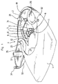
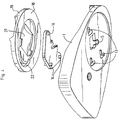
- the first embodiment of Figures 1 and 2, and the second embodiment of Figures 3 and 4 have the same elements functional and the same kinematics, from the point of view of lens bending Intraocular. They differ only in the material used (synthetic material in Figures 1 and 2, metal such as aluminum in Figures 3 and 4) and thereby that the first embodiment has a hinged cover 30, and can make packaging office for intraocular lens 3.
- the folding device comprises a frame 1 defining a bottom 2 for receiving an intraocular lens 3 to be folded in order to its implantation in the eye of a patient.
- the frame 1 is generally flat and has shapes and dimensions which are preferably adapted to allow the gripping the device in one hand, the other hand being used to actuate maneuvering means 4 mounted on the frame 1 for folding the lens intraocular 3.
- the frame 1 and the bottom 2 are assumed extend horizontally.
- the intraocular lens 3 includes an optical part 3a in flexible foldable material and two haptic handles 3b in C.
- the receiving base 2 is advantageously provided with a cylindrical recess or central bore 5, of vertical axis, facing the part optic 3a, of smaller diameter than that of the optical part 3a, to facilitate the folding and minimizing the friction of the peripheral edges of the optical part 3a on the bottom 2 during folding.
- the diameter of the recess or hole central 5 is for example of the order of 4mm.
- the bottom 2 carries two fixed studs 6, 7, arranged at least substantially 90 ° from each other around and near the recess or hole central 5.
- Each of these studs 6, 7 defines a face 8, respectively 10, which extends upward from the bottom 2, and at least substantially perpendicular to the radial direction of the recess or central bore 5 and of the optical part 3a of a lens in place on the bottom 2.
- These faces 8, 10 define two fixed folding spans 8, 10 adapted to come into contact with the periphery of the optical part 30.
- the device comprises an intermediate moving part 12 mounted and guided on the frame 1 thanks to at least one V-shaped groove 13 on the bottom 2 receiving at least one stud 14 of the intermediate movable part 12, in particular thanks to a set of grooves 13 and nipples 14.
- the bottom 2 has three V-shaped grooves 13, each having two branches, namely a first branch and a second branch forming between them an angle at less substantially equal to the angle formed between the two potential fold lines desired for the lens 3.
- the different grooves 13 (that is to say their corresponding branches) are parallel to each other.
- the moving part intermediate 12 has three studs 14 projecting downwardly to be able to slide in the three grooves 13. The intermediate moving part 12 can thus move in translation relative to the bottom 2 according to one or the other directions corresponding to the directions of the two branches of the grooves 13.
- the intermediate movable part 12 has two faces 9, respectively 11, which extend upward relative to the bottom 2.
- these faces 9, 11 extend at least substantially perpendicular to the radial direction of the recess or central drilling 5 and of the optical part 3a of a lens in place on the bottom 2.
- Each of these faces 9, 11 which moves with the part intermediate mobile 12 defines a mobile folding span 9, 11 adapted for come into contact with the periphery of the optical part 3a of the lens.
- the folding device thus comprises two pairs 8, 9 and 10, 11 of folding spans.
- the first pair 8, 9 includes a fixed folding span 8 secured to the bottom 2 and a movable folding surface 9 secured to the movable part intermediate 12, and these two folding spans 8, 9 are adapted to be able be placed in contact with the periphery of the optical part 3a of the lens 3 in place on the bottom 2 in two opposite contact zones according to a first diametrical direction 15 at least substantially parallel to the direction of first branches of V-grooves 13.
- the second pair 10, 11 includes a folding span fixed 10 secured to the bottom 2 and a movable folding surface 11 secured to the part intermediate mobile 12, and these two folding spans 10, 11 are suitable for be able to be placed in contact with the periphery of the optical part 3a of the lens 3 in place on the bottom 2 in two opposite contact zones according to a second diametrical direction 16 at least substantially perpendicular to the first diametral direction 15, this second diametral direction 16 being at less substantially parallel to the direction of the second branches of the grooves in V 13.
- the two movable folding reaches 10, 11 are arranged around the central recess or bore 5, at least substantially 90 ° from each other around and near this recess or central drilling 5.
- the two folding spans 8, 9 and 10, 11 in the same pair extend at least substantially parallel to each other and perpendicularly to the corresponding diametral direction 15, 16.
- the intermediate moving part 12 is adapted for allow the passage of a haptic loop 3b around and behind one 11 of the two movable folding seats (that of the second pair), and has a recess 17 to do this.
- the other haptic loop 3b of the lens 3 can be passed behind the stud 7 defining the fixed folding range 10 of the second pair.
- the room intermediate mobile 12 and / or the other pad 6 are adapted to prevent the passage of the haptic loops 3b behind the other folding staves 8, 9 of the first pair of folding staves. In this way, lens 3 cannot be placed only in one possible orientation relative to the bottom 2.
- the folding device also includes a movable member for rotary actuator 18 in the general shape of a crown which acts as a means of maneuver.
- This movable operating member 18 is hollowed out in its central part to present an access light 21 facing the lens 3 in place on the bottom 2, and has a circular external edge 19 sliding against one or several cylindrical guide face (s) 20 integral with the frame 1 adapted for receive the movable operating member 18 and guide it in rotation relative to the frame 1.
- the mobile rotary actuator 18 is connected to the movable folding surfaces 9, 11, that is to say at the intermediate movable part 12, by means of a cam mechanism 22 and contact slide 23.
- the intermediate movable part 12 carries a slide 23 which extends projecting towards the top to cooperate with a cam 22 hollowed out under the movable member 18.
- the cam shape 22 is adapted so that when the member operating mobile 18 is moved in a first direction of rotation 24 (FIG. 5b), the intermediate moving part 12 is moved in the first direction diametral 15 (the pins 14 being guided in the first branches of the grooves 13), and when it is moved in the second direction of rotation 25 (FIG. 5c) opposite the first direction of rotation 24, the intermediate movable part 12 is moved in the second diametrical direction 16 (the pins 14 being guided in the second branches of the grooves 13).
- the movable operating member 18 covers the part intermediate mobile 12 and the assembly is held in place axially by relative to the frame 1 by stops 26, 27.
- the device comprises a fixed stop 26 extending horizontally projecting above the edge of the upper face of the movable operating member 18 and, diametrically opposite to this fixed stop 26, a removable stop 27 fixed by a screw 28, so as to allow the mounting and dismounting of the movable member operating 18.
- the mobile operating member 18 comprises two maneuvering notches 29 to facilitate its manual grip and its rotary actuation.
- the first mode of actuation ( Figure 5b) of the organ operating mobile 18 in the first direction of rotation 24 has the effect of bring the mobile folding seat 9 radially closer to the first pair of folding spans, of the fixed folding span 8 of this first pair, according to the first radial direction 15, which causes the folding of the optical part 3a of the lens along a first fold line at 6 am to 12 pm at least substantially perpendicular to the first diametrical direction 15.
- the second mode of actuation ( Figure 5c) of the organ operating mobile 18 in the second direction of rotation 25 has the effect of bring the mobile folding seat 11 radially closer to the second pair of folding spans, of the fixed folding span 10 of this second pair, according to the second radial direction 16, which causes the folding of the optical part 3a of the lens along a second fold line at 3 am to 9 am at least substantially perpendicular to the second diametrical direction 16.
- the cover 30 of the folding device of the first mode of realization is articulated on the side of the frame 1, for example by a film hinge 35 formed of a thin strip of synthetic material.
- This cover 30 includes a locking pin 31 in the closed position forcibly engaged in an orifice 32 of the frame 1, and an axial extension 33 extending downwards in the closed position for maintain a lens 3 axially in place on the receiving bottom 2.
- the cover 30 in the closed position, is engaged between two straight walls 34 of the movable operating member 18, so that it then prohibits any movement untimely rotation of this movable operating member 18.
- the folding device according to the invention essentially consists of three parts movable relative to each other, namely the frame 1, the movable part intermediate 12 and the movable operating member 18.
- the folding device is formed only of two parts: the frame 1 and the movable member maneuver 18 rotatably mounted on this frame 1.
- Each movable folding span 9a, 9b, 1a, 11b is formed by an end stud of a flexible arm 36, 37 integral of frame 1 extending horizontally and perpendicular to the direction diametral according to which the staff must move.
- the first pair of folding staves includes two movable folding spans 9a, 9b and the second pair of folding spans comprises two movable folding spans 11a, 11b.
- the mobile organ of operation 18 comprises two cams 22a, 22b delimiting its central lumen 21, and adapted to come into contact simultaneously with the semi-cylindrical posterior faces 38 or 39 of the two studs forming the two folding spans 9a, 9b or 11a, 11b of the same pair of folding spans.
- One 22a of the cams one 9a, 1a of the folding spans, while the other cam 22b controls the other folding span 9b, 11b.
- the folding ranges 9a, 9b of the first pair have notches forming housing for receiving the handles haptics 3b of the lens.
- the lens 3 is maintained in place axially, that is to say carried by the frame 1, only thanks to these reception accommodation, by its haptic handles 3b.
- the movable folding spans 9a, 9b, 11a, 11b can present, as for the embodiment of FIG. 7b represented, radial inward extensions under the optical part 3a of the lens so to form, at least in part, means for receiving the lens 3 and to wear it axially.
- the movable operating member 18 has a tab 40 actuation and is guided on the frame 1 by guiding means in rotation at circular groove (s) and nipple (s).
- the cams 22a, 22b come to contact of the rear faces 38 of the studs forming the two folding spans mobiles 9a, 9b of the first pair which radially approach one of the other by bending the arms 36 which carry them.
- This displacement in flexion is comparable to a translation in the first diametrical direction 15 counts given the length of the arms 36 and the small displacement stroke induced.
- the lens 3 is then folded along a fold line from 6 am to 12 pm
- the folding device comprises a movable operating member 42 guided not in rotation on the frame 1, but in translation according to one or the other of the two directions 49, 50 perpendicular to the first diametrical direction 15 and, respectively, to the second diametrical direction 16.
- a V-shaped groove 43 is formed in the movable member of operation 42, and a stud 44 secured to the frame 1 slides in the V-shaped groove 43.
- the mobile operating member 42 includes two lights 45, 46 trapezoidal, 90 ° from each other, each defining a pair of straight cams 47, 48 converging with respect to each other for the faces posterior 38, 39 of the pads carrying the movable folding spans 9a, 9b, 11a, 11b.
- the frame 1 carries two pairs of folding spans 9a, 9b, 11a, 11b movable formed by studs at the end of flexible arms 36, 37 of the frame 1.
- Each stud also has a radial extension (FIG. 7b) towards the interior under the optical part 3a of the lens for receiving and carrying it axially.
- the radial length of these extensions is not too great for do not prevent correct folding of the lens 3.
- the two cams 47 of the first light 45 come into contact with the rear faces 38 of the pads carrying the two movable folding staves 9a, 9b of the first pair, and bring them together radially from one another in the first diametrical direction 15.
- the lens 3 is folded along a fold line from 6h to 12h.
- the two cams 48 of the second light 46 come to contact of the rear faces 39 of the pads carrying the movable folding surfaces 11a, 11b of the second pair, and bring them radially closer to each other in the second diametrical direction 16.
- the lens 3 is folded along a line folding 3 am-9am.
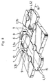
- the embodiment of Figure 8 differs from the previous one by the fact that the mobile operating member 42 is replaced by two members maneuvering mobiles 51, 52, guided in translation on the frame 1, one for each pair of folding staves.
- the device includes a first pair of folding staves 8, 9 consisting of a fixed folding 8 secured to the frame 1 and a movable folding seat 9 which is formed of the end face of the first movable operating member 51.
- the second pair consists of a fixed folding surface 10 secured to the frame 1 and a movable folding seat 11 which is formed from the end face of the second mobile operating member 52.
- Each movable operating member 51, 52 is guided in translation relative to the frame 1 in a direction which corresponds to the direction diametral 15, 16 according to which the movable folding span 9, 11 which it carries must be moved.
- the diametrical directions 15, 16, and therefore the corresponding fold lines are 90 ° from each other.
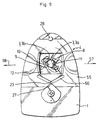
- FIG. 9 differs from that of Figures 3 and 4 by the fact that the movable rotating member 18 is replaced by a movable operating member 55 guided in translation in a single direction (i.e. along a single axis of translation), in one direction or in the other, in relation to the frame 1.
- the slide 23 of the intermediate moving part 12 is engaged in a V-shaped cam 56 of the movable operating member 55, the branches of this cam 56 being adapted so that the first direction of translation 57 of the member 55 corresponds to the first mode of actuation, that is to say to the displacement of the movable folding span 9 of the first pair for folding 6h-12h of lens 3, and so that the second direction of translation 58, opposite to first, corresponds to the second actuation mode, that is to say to the displacement of the movable folding span 11 of the second pair for a folding the lens from 3 am to 9 am.
- Figures 10 and 11 is similar to that of FIGS. 3 and 4, but comprises two intermediate movable parts 12a, 12b, defining two pairs of movable folding spans 9a, 9b, 11a, 11b.
- each intermediate movable part 12a, 12b is guided in translation on the frame 1 thanks to at least one V-shaped groove 13a, 13b at the bottom 2 of the frame 1 receiving at less a stud 14a, 14b secured, respectively, to the moving part intermediate 12a, 12b corresponding.
- a single V-shaped groove 13a, 13b is provided for each moving part 12a, 12b which is also guided by circular guide surfaces 68a, 68b of the movable operating member 18 receiving lugs 69a, 69b of the part 12a, 12b.
- the mobile operating member 18 is moreover similar to that of the mode of Figures 3 and 4, is in the form of a crown, and is guided in rotation with respect to the frame 1.
- this mobile maneuvering member 18 comprises two cams 71a, 71b recessed in its lower face 72 to receive, respectively, a contact slide 23a, 23b which extends projecting towards the top of each intermediate moving part 12a, 12b.
- Each pair of movable folding spans 9a, 9b and 11a, 11b comprises a first bearing 9a, 11a integral with the first movable part intermediate 12a, and a second bearing 9b, 11b secured to the second part intermediate mobile 12b.
- the shape of the cams 71a, 71b of the movable member of operation 18 and means 13a, 14a, 13b, 14b for guiding the moving parts intermediaries 12a, 12b relative to the frame 1 are adapted so that when the movable operating member 18 is moved in a first direction of rotation, the two intermediate moving parts 12a, 12b are displaced in translation in approaching each other in the same first diametrical direction, the movable folding spans 9a, 9b of a first pair approaching one of the other, the pins 14a, 14b being guided in the first branches, parallel one from the other, grooves 13a, 13b, and, when the movable operating member 18 is moved in the second direction of rotation opposite to the first, the parts intermediate mobiles 12a, 12b are moved in translation while approaching from each other in the same second diametrical direction distinct from the first, the movable folding spans 11a, 11b of a second pair are approaching one from the other, the pins 14a, 14b being guided in the second branches, parallel to
- the mobile operating member 18 covers the two intermediate moving parts 12a, 12b and is held in place axially by relative to the frame 1 thanks to the stops 26, 27.
- the bottom 2 comprises a central recess 5 for receiving the lens to be folded, and reception accommodation 70 haptic loops.
- Figures 10 and 11 is therefore similar to that of FIGS. 3 and 4, and is essentially only distinguished therefrom by the fact that fixed folding spans 8, 10 of FIGS. 3 and 4 are replaced by movable folding spans 9b, 11b secured to a second movable part intermediate 12b.
- the device essentially consists of four moving parts, one per compared to the others, namely the frame 1, the two intermediate moving parts 12a, 12b, and the mobile operating member 18.
- the invention may be subject to other variants of production.
- certain characteristics of the different variants may be combined with each other.
- the invention is also applicable for folding lenses intraoculars with haptic parts which are not C-handles.
Claims (15)
- Vorrichtung zum Falten einer Intraokularlinse (3) mit flexiblem optischem Teil (3a) vor ihrer Implantation, die Folgendes umfasst:dadurch gekennzeichnet, dass die Betätigungsmittel (4) so gestaltet sind, dass, wenn sich eine Linse (3) in den Aufnahmemitteln (2) befindet:Mittel (2) zum Aufnehmen der Linse (3),wenigstens ein Paar Faltanschläge (8, 9, 9a, 9b, 10, 11, 11a, 11b), die so gestaltet sind, dass sie in Kontakt mit dem optischen Teil (3a) der Linse (3) in zwei gegenüberliegenden Kontaktzonen in derselben diametralen Richtung platziert werden können,Betätigungsmittel (4) in Verbindung mit wenigstens einem Faltanschlag (9, 9a, 9b, 11, 11a, 11b), die so gestaltet sind, dass sie bei Betätigung eine Bewegung in Richtung auf einen anderen Faltanschlag (8, 9b, 11b, 11a) desselben Paares von Faltanschlägen bewirken,so dass die Linse (3) in der einen oder der anderen der unterschiedlichen Faltlinien gefaltet werden kann.in einem ersten Arbeitsmodus der Betätigungsmittel (4) ein erstes Paar Faltanschläge (8, 9, 9a, 9b) in Kontakt mit der Peripherie des optischen Teils (3a) der Linse (3) in zwei gegenüberliegenden Kontaktzonen in einer ersten diametralen Richtung (15) kommt, wobei dieses erste Paar Faltanschläge (8, 9, 9a, 9b) so gestaltet ist, dass es unter der Wirkung der Arbeit von wenigstens einem beweglichen Betätigungsmechanismus (18, 42, 51, 52, 55, 62a, 62b) in diesem ersten Arbeitsmodus eine Faltung der Linse gemäß einer ersten Faltlinie erzeugt,in wenigstens einem zweiten Arbeitsmodus der Betätigungsmittel (4) ein zweites Paar Faltanschläge (10, 11, 11a, 11b), das sich von dem ersten Paar Faltanschläge unterscheidet, in Kontakt mit der Peripherie des optischen Teils (3a) der Linse (3) in zwei gegenüberliegenden Kontaktzonen in einer zweiten diametralen Richtung (16) kommt, die sich von der ersten diametralen Richtung (15) unterscheidet, wobei dieses zweite Paar Faltanschläge (10, 11, 11a, 11b) so gestaltet ist, dass unter der Wirkung der Arbeit von wenigstens einem beweglichen Betätigungsmechanismus (18, 42, 51, 52, 55, 62a, 62b) in dem zweiten Arbeitsmodus eine Faltung der Linse in einer zweiten Faltlinie erzeugt wird, die sich von der ersten Faltlinie unterscheidet,
- Vorrichtung nach Anspruch 1, dadurch gekennzeichnet, dass die erste diametrale Richtung (15) und die zweite diametrale Richtung (16) zwischen sich einen Winkel zwischen 60° und 120° bilden, so dass die Linse (3) gemäß der einen oder anderen der beiden Faltlinien gefaltet werden kann, die zwischen sich einen Winkel zwischen 60° und 120° bilden.
- Vorrichtung nach einem der Ansprüche 1 und 2, dadurch gekennzeichnet, dass sie ein Gehäuse (1) umfasst, umfassend die Mittel (2) zum Aufnehmen der Linse (3), dadurch, dass wenigstens einer (9, 9a, 9b, 11, 11a, 11b) der beiden Faltanschläge, beweglicher Faltanschlag (9, 9a, 9b, 11, 11a, 11b) genannt, von wenigstens einem der Paare von Faltanschlägen in Bezug auf das Gehäuse (1) so montiert ist, dass er sich dem anderen Faltanschlag (8, 9b, 9a, 10, 11b, 11a) dieses Paares von Faltanschlägen nähern kann, und dadurch, dass die Betätigungsmittel (4) wenigstens einen beweglichen Betätigungsmechanismus (18, 42, 51, 52, 55, 62a, 62b) umfassen, der mit wenigstens einem beweglichen Faltanschlag (9, 9a, 9b, 11, 11a, 11b) verbunden ist, um die Bewegungen in Bezug auf die Aufnahmemittel (2) zu bewirken, wenn dieser bewegliche Betätigungsmechanismus betätigt wird.
- Vorrichtung nach einem der Ansprüche 1 bis 3, dadurch gekennzeichnet, dass die Betätigungsmittel (4) wenigstens zwei bewegliche Betätigungsmechanismen (51, 52) umfassen, von denen einer (51) mit wenigstens einem ersten beweglichen Faltanschlag (9) eines ersten Paares von Faltanschlägen (8, 9) und der andere (52) mit wenigstens einem zweiten beweglichen Faltanschlag (11) eines zweiten Paares von Faltanschlägen (10, 11) verbunden ist.
- Vorrichtung nach einem der Ansprüche 1 bis 3, dadurch gekennzeichnet, dass die Betätigungsmittel (4) einen beweglichen Betätigungsmechanismus (18, 42, 55) umfassen, der mit wenigstens einem ersten beweglichen Faltanschlag (9, 9a, 9b) des ersten Paares von Faltanschlägen (8, 9, 9a, 9b) und mit wenigstens einem zweiten beweglichen Faltanschlag (11, 11a, 11b) des zweiten Paares von Faltanschlägen (10, 11, 11a, 11b) verbunden und so gestaltet ist, dass er entweder im ersten Arbeitsmodus oder im zweiten Arbeitsmodus betätigt werden kann.
- Vorrichtung nach Anspruch 5, dadurch gekennzeichnet, dass der bewegliche Betätigungsmechanismus (18) drehbar in Bezug auf das Gehäuse (1) montiert ist, dadurch, dass der erste Arbeitsmodus einer Rotationsbewegung des beweglichen Betätigungsmechanismus (18) in einer ersten Drehrichtung (24) entspricht, und dadurch, dass der zweite Arbeitsmodus einer Drehbewegung des beweglichen Betätigungsmechanismus (18) in der zweiten Drehrichtung (25) entspricht, die der ersten Drehrichtung (24) entgegengesetzt ist.
- Vorrichtung nach Anspruch 5, dadurch gekennzeichnet, dass der bewegliche Betätigungsmechanismus (42) in Bezug auf das Gehäuse (1) so montiert ist, dass er in wenigstens zwei verschiedenen Translationsrichtungen (49, 50) bewegt werden kann, von denen die eine (49) einem ersten Arbeitsmodus entspricht, während die andere (50) einem zweiten Arbeitsmodus entspricht.
- Vorrichtung nach Anspruch 5, dadurch gekennzeichnet, dass der bewegliche Betätigungsmechanismus (55) in Bezug auf das Gehäuse (1) so montiert ist, dass er in wenigstens einer Translationsrichtung und wenigstens zwei dieser Translationsrichtung entgegengesetzten Richtungen (57, 58) bewegt werden kann, von denen die eine (57) dem ersten Arbeitsmodus entspricht, während die andere (58) dem zweiten Arbeitsmodus entspricht.
- Vorrichtung nach einem der Ansprüche 5 bis 8, dadurch gekennzeichnet, dass ein erster beweglicher Faltanschlag (9) des ersten Paares von Faltanschlägen (8, 9) und ein zweiter beweglicher Faltanschlag (11) des zweiten Paares von Faltanschlägen (10, 11) aus einem Stück mit einem beweglichen Zwischenstück (12) ausgebildet sind, das in Bezug auf das Gehäuse (1) montiert ist und geführt wird und mit dem beweglichen Betätigungsmechanismus (18) so verbunden ist, dass es unter der Wirkung der Arbeit dieses beweglichen Betätigungsmechanismus (18) in dem einen oder dem anderen Arbeitsmodus bewegt werden kann.
- Vorrichtung nach einem der Ansprüche 1 bis 9, dadurch gekennzeichnet, dass ein beweglicher Betätigungsmechanismus (18, 42, 55) mit jedem beweglichen Faltanschlag (9, 9a, 9b, 11, 11a, 11b) verbunden ist, dessen Bewegungen er mit einem System aus Nocken (22, 47, 48, 56) und Kontaktschieber (23, 38, 39) bewirkt.
- Vorrichtung nach einem der Ansprüche 1 bis 10, dadurch gekennzeichnet, dass jedes Paar Faltanschläge einen festen Faltanschlag (8, 10) in Bezug auf das Gehäuse (1) umfasst.
- Vorrichtung nach einem der Ansprüche 1 bis 11, dadurch gekennzeichnet, dass jeder bewegliche Faltanschlag (9, 9a, 9b, 11, 11a, 11b) in Bezug auf das Gehäuse (1) so montiert ist, dass er wenigstens im Wesentlichen translationsbeweglich ist.
- Vorrichtung nach einem der Ansprüche 1 bis 12, dadurch gekennzeichnet, dass die Aufnahmemittel (2) so gestaltet sind, dass sie die Intraokularlinse (3) in nur einer möglichen Orientierungsrichtung aufnehmen können.
- Vorrichtung nach einem der Ansprüche 1 bis 13, dadurch gekennzeichnet, dass sie eine Umhüllung für eine Intraokularlinse (3) darstellt und eine Kappe (30) aufweist, die auf der in den Aufnahmemitteln (2) befindlichen Linse (3) geschlossen wird, wobei diese Kappe (30) so gestaltet ist, dass sie geöffnet werden kann, damit die Linse (3) zugängig ist.
- Vorrichtung nach Anspruch 14, dadurch gekennzeichnet, dass die Kappe (30) so gestaltet ist, dass in der geschlossenen Position auf der Linse (3) jede ungewollte Bewegung der Betätigungsmittel (4) verhütet und in der offenen Position die Betätigung der Betätigungsmittel (4) in dem einen oder dem anderen Arbeitsmodus zugelassen wird.
Applications Claiming Priority (3)
| Application Number | Priority Date | Filing Date | Title |
|---|---|---|---|
| FR9806155A FR2778556B1 (fr) | 1998-05-15 | 1998-05-15 | Dispositif de pliage de lentille intraoculaire |
| FR9806155 | 1998-05-15 | ||
| PCT/FR1999/001006 WO1999059504A1 (fr) | 1998-05-15 | 1999-04-28 | Dispositif de pliage de lentille intraoculaire |
Publications (2)
| Publication Number | Publication Date |
|---|---|
| EP1077657A1 EP1077657A1 (de) | 2001-02-28 |
| EP1077657B1 true EP1077657B1 (de) | 2003-08-27 |
Family
ID=9526398
Family Applications (1)
| Application Number | Title | Priority Date | Filing Date |
|---|---|---|---|
| EP99915857A Expired - Lifetime EP1077657B1 (de) | 1998-05-15 | 1999-04-28 | Vorrichtung zum falten einer intraokularen linse |
Country Status (9)
| Country | Link |
|---|---|
| US (1) | US6537282B1 (de) |
| EP (1) | EP1077657B1 (de) |
| JP (1) | JP2002515291A (de) |
| AT (1) | ATE247934T1 (de) |
| CA (1) | CA2332425A1 (de) |
| DE (1) | DE69910765T2 (de) |
| ES (1) | ES2207198T3 (de) |
| FR (1) | FR2778556B1 (de) |
| WO (1) | WO1999059504A1 (de) |
Families Citing this family (10)
| Publication number | Priority date | Publication date | Assignee | Title |
|---|---|---|---|---|
| JP2001346817A (ja) * | 2000-06-08 | 2001-12-18 | Menicon Co Ltd | 眼内レンズケース |
| EP1391185B1 (de) * | 2001-05-25 | 2012-06-27 | Hoya Healthcare Corporation | Aufbewahrungsbehälter mit einer Faltfunktion für weiche Intraokularlinsen |
| US8623082B2 (en) | 2002-07-26 | 2014-01-07 | Amo Groningen B.V. | Method and device for manipulation of an intraocular lens |
| BR0312968A (pt) * | 2002-07-26 | 2005-06-14 | Pharmacia Groningen Bv | Método e dispositivo para manipulação de uma lente intraocular |
| WO2004087019A1 (ja) * | 2003-03-28 | 2004-10-14 | Menicon Co., Ltd. | 眼内レンズの流通コンテナ |
| IL190577A0 (en) * | 2008-04-02 | 2008-12-29 | Nulens Ltd | Cartridge for storing an iol and forceps for use therewith |
| JP6967374B2 (ja) * | 2017-06-01 | 2021-11-17 | Hoya株式会社 | レンズ収納容器 |
| WO2020121272A1 (en) * | 2018-12-13 | 2020-06-18 | Alcon Inc. | Haptic optic management system utilizing rotating cams |
| US11534292B2 (en) * | 2018-12-19 | 2022-12-27 | Alcon Inc. | Folding device for intraocular lens injector |
| WO2021038412A1 (en) * | 2019-08-23 | 2021-03-04 | Alcon Inc. | Packaging-integrated manually actuated intraocular lens cartridge and lens delivery device |
Family Cites Families (8)
| Publication number | Priority date | Publication date | Assignee | Title |
|---|---|---|---|---|
| DE4039119C1 (de) | 1990-12-07 | 1991-09-05 | Dieter Dr.Med. 8904 Friedberg De Klaas | |
| US5318011A (en) * | 1992-02-04 | 1994-06-07 | Escalon Ophthalmics, Inc. | Iris protector/dilator and method of using the same |
| US5281227A (en) * | 1992-11-09 | 1994-01-25 | Allergan, Inc. | Lens case with IOL folding device |
| US5290293A (en) | 1993-06-21 | 1994-03-01 | Alcon Surgical, Inc. | Intraocular lens folder |
| US5629577A (en) * | 1994-07-15 | 1997-05-13 | Micro Medical Devices | Miniature linear motion actuator |
| AU710419B2 (en) * | 1994-08-05 | 1999-09-23 | Bausch & Lomb Incorporated | Device for inserting a flexible intraocular lens |
| US5702400A (en) * | 1996-12-11 | 1997-12-30 | Alcon Laboratories, Inc. | Intraocular lens folder |
| US5947975A (en) * | 1997-03-07 | 1999-09-07 | Canon Staar Co., Inc. | Inserting device for deformable intraocular lens |
-
1998
- 1998-05-15 FR FR9806155A patent/FR2778556B1/fr not_active Expired - Fee Related
-
1999
- 1999-04-28 CA CA002332425A patent/CA2332425A1/fr not_active Abandoned
- 1999-04-28 US US09/700,399 patent/US6537282B1/en not_active Expired - Fee Related
- 1999-04-28 JP JP2000549171A patent/JP2002515291A/ja active Pending
- 1999-04-28 EP EP99915857A patent/EP1077657B1/de not_active Expired - Lifetime
- 1999-04-28 WO PCT/FR1999/001006 patent/WO1999059504A1/fr active IP Right Grant
- 1999-04-28 DE DE69910765T patent/DE69910765T2/de not_active Expired - Fee Related
- 1999-04-28 AT AT99915857T patent/ATE247934T1/de not_active IP Right Cessation
- 1999-04-28 ES ES99915857T patent/ES2207198T3/es not_active Expired - Lifetime
Also Published As
| Publication number | Publication date |
|---|---|
| EP1077657A1 (de) | 2001-02-28 |
| WO1999059504A1 (fr) | 1999-11-25 |
| US6537282B1 (en) | 2003-03-25 |
| FR2778556A1 (fr) | 1999-11-19 |
| ATE247934T1 (de) | 2003-09-15 |
| ES2207198T3 (es) | 2004-05-16 |
| JP2002515291A (ja) | 2002-05-28 |
| FR2778556B1 (fr) | 2000-11-10 |
| CA2332425A1 (fr) | 1999-11-25 |
| DE69910765T2 (de) | 2004-06-17 |
| DE69910765D1 (de) | 2003-10-02 |
Similar Documents
| Publication | Publication Date | Title |
|---|---|---|
| EP0077277A1 (de) | Verfahren und Vorrichtung zur Anbringung von Blutgefässklammern und Blutgefässklammern dafür | |
| EP1077657B1 (de) | Vorrichtung zum falten einer intraokularen linse | |
| EP0133393B1 (de) | Vorrichtung zum Verpacken und Handhaben von Gegenständen ohne unmittelbaren manuellen Kontakt | |
| EP1994852B1 (de) | Schminkbox | |
| FR2578415A1 (fr) | Lentille intra-oculaire articulee | |
| EP1875826A1 (de) | Schmuckstück mit eimem beweglichen Element | |
| FR2578724A1 (fr) | Casque, notamment pour pilotes d'avions | |
| EP2606762A1 (de) | Armbandverschluss mit verschiedenen Längenregulierungen | |
| FR2515956A1 (fr) | Cristallin artificiel ou implant, et ensemble comportant ledit cristallin artificiel et un dispositif porteur et applicateur utilise dans la chirurgie de la cataracte | |
| FR2464488A1 (fr) | Lunette d'approche binoculaire a mise au point interne | |
| EP0661938B1 (de) | Faltverschluss für armbänder | |
| FR2542099A1 (fr) | Monture de lunettes a charnieres elastiques | |
| EP0855866B1 (de) | Verschluss mit knopf | |
| EP1296596B1 (de) | Medizinische zange mit zwei schwenkbaren backen | |
| WO2018115605A1 (fr) | Application de produit cosmétique, comme du mascara | |
| FR2751431A1 (fr) | Monture de lunettes a branches pivotantes | |
| EP0323787B1 (de) | Vorrichtung zum Zentrieren und Aufkitten von optischen Linsen | |
| EP0514262B1 (de) | Intraokulare Vorrichtung für die Implantation in dem Kapelsack | |
| FR2474303A1 (fr) | Instrument a main de precision, notamment de micro chirurgie | |
| EP2120625B1 (de) | Uhrarmband | |
| EP1042999A1 (de) | Halter für eine Intraocularlinse | |
| WO2018087457A1 (fr) | Charnière pour monture de lunettes | |
| FR2716739A1 (fr) | Porte-étiquette pour article de classement du type dossier suspendu. | |
| FR2631545A1 (fr) | Applicateur pour l'implantation epicorneenne de lentilles souples | |
| EP3801371B1 (de) | Vorrichtung zur aufbewahrung von orthodontischen zangen |
Legal Events
| Date | Code | Title | Description |
|---|---|---|---|
| PUAI | Public reference made under article 153(3) epc to a published international application that has entered the european phase |
Free format text: ORIGINAL CODE: 0009012 |
|
| 17P | Request for examination filed |
Effective date: 20001006 |
|
| AK | Designated contracting states |
Kind code of ref document: A1 Designated state(s): AT BE CH CY DE DK ES FI FR GB GR IE IT LI LU MC NL PT SE |
|
| GRAH | Despatch of communication of intention to grant a patent |
Free format text: ORIGINAL CODE: EPIDOS IGRA |
|
| GRAS | Grant fee paid |
Free format text: ORIGINAL CODE: EPIDOSNIGR3 |
|
| GRAA | (expected) grant |
Free format text: ORIGINAL CODE: 0009210 |
|
| AK | Designated contracting states |
Designated state(s): AT BE CH CY DE DK ES FI FR GB GR IE IT LI LU MC NL PT SE |
|
| PG25 | Lapsed in a contracting state [announced via postgrant information from national office to epo] |
Ref country code: NL Free format text: LAPSE BECAUSE OF FAILURE TO SUBMIT A TRANSLATION OF THE DESCRIPTION OR TO PAY THE FEE WITHIN THE PRESCRIBED TIME-LIMIT Effective date: 20030827 Ref country code: FI Free format text: LAPSE BECAUSE OF FAILURE TO SUBMIT A TRANSLATION OF THE DESCRIPTION OR TO PAY THE FEE WITHIN THE PRESCRIBED TIME-LIMIT Effective date: 20030827 Ref country code: CY Free format text: LAPSE BECAUSE OF FAILURE TO SUBMIT A TRANSLATION OF THE DESCRIPTION OR TO PAY THE FEE WITHIN THE PRESCRIBED TIME-LIMIT Effective date: 20030827 Ref country code: AT Free format text: LAPSE BECAUSE OF FAILURE TO SUBMIT A TRANSLATION OF THE DESCRIPTION OR TO PAY THE FEE WITHIN THE PRESCRIBED TIME-LIMIT Effective date: 20030827 |
|
| REG | Reference to a national code |
Ref country code: GB Ref legal event code: FG4D Free format text: NOT ENGLISH |
|
| REG | Reference to a national code |
Ref country code: CH Ref legal event code: EP |
|
| REG | Reference to a national code |
Ref country code: IE Ref legal event code: FG4D Free format text: FRENCH |
|
| REF | Corresponds to: |
Ref document number: 69910765 Country of ref document: DE Date of ref document: 20031002 Kind code of ref document: P |
|
| PG25 | Lapsed in a contracting state [announced via postgrant information from national office to epo] |
Ref country code: SE Free format text: LAPSE BECAUSE OF FAILURE TO SUBMIT A TRANSLATION OF THE DESCRIPTION OR TO PAY THE FEE WITHIN THE PRESCRIBED TIME-LIMIT Effective date: 20031127 Ref country code: GR Free format text: LAPSE BECAUSE OF FAILURE TO SUBMIT A TRANSLATION OF THE DESCRIPTION OR TO PAY THE FEE WITHIN THE PRESCRIBED TIME-LIMIT Effective date: 20031127 Ref country code: DK Free format text: LAPSE BECAUSE OF FAILURE TO SUBMIT A TRANSLATION OF THE DESCRIPTION OR TO PAY THE FEE WITHIN THE PRESCRIBED TIME-LIMIT Effective date: 20031127 |
|
| GBT | Gb: translation of ep patent filed (gb section 77(6)(a)/1977) |
Effective date: 20031217 |
|
| PG25 | Lapsed in a contracting state [announced via postgrant information from national office to epo] |
Ref country code: PT Free format text: LAPSE BECAUSE OF FAILURE TO SUBMIT A TRANSLATION OF THE DESCRIPTION OR TO PAY THE FEE WITHIN THE PRESCRIBED TIME-LIMIT Effective date: 20040127 |
|
| NLV1 | Nl: lapsed or annulled due to failure to fulfill the requirements of art. 29p and 29m of the patents act | ||
| PG25 | Lapsed in a contracting state [announced via postgrant information from national office to epo] |
Ref country code: LU Free format text: LAPSE BECAUSE OF NON-PAYMENT OF DUE FEES Effective date: 20040428 |
|
| PG25 | Lapsed in a contracting state [announced via postgrant information from national office to epo] |
Ref country code: MC Free format text: LAPSE BECAUSE OF NON-PAYMENT OF DUE FEES Effective date: 20040430 Ref country code: LI Free format text: LAPSE BECAUSE OF NON-PAYMENT OF DUE FEES Effective date: 20040430 Ref country code: CH Free format text: LAPSE BECAUSE OF NON-PAYMENT OF DUE FEES Effective date: 20040430 Ref country code: BE Free format text: LAPSE BECAUSE OF NON-PAYMENT OF DUE FEES Effective date: 20040430 |
|
| REG | Reference to a national code |
Ref country code: ES Ref legal event code: FG2A Ref document number: 2207198 Country of ref document: ES Kind code of ref document: T3 |
|
| PLBE | No opposition filed within time limit |
Free format text: ORIGINAL CODE: 0009261 |
|
| STAA | Information on the status of an ep patent application or granted ep patent |
Free format text: STATUS: NO OPPOSITION FILED WITHIN TIME LIMIT |
|
| 26N | No opposition filed |
Effective date: 20040528 |
|
| BERE | Be: lapsed |
Owner name: *CHAUVIN OPSIA Effective date: 20040430 |
|
| REG | Reference to a national code |
Ref country code: CH Ref legal event code: PL |
|
| PGFP | Annual fee paid to national office [announced via postgrant information from national office to epo] |
Ref country code: GB Payment date: 20050314 Year of fee payment: 7 |
|
| PGFP | Annual fee paid to national office [announced via postgrant information from national office to epo] |
Ref country code: FR Payment date: 20050401 Year of fee payment: 7 |
|
| PGFP | Annual fee paid to national office [announced via postgrant information from national office to epo] |
Ref country code: IE Payment date: 20050414 Year of fee payment: 7 |
|
| PGFP | Annual fee paid to national office [announced via postgrant information from national office to epo] |
Ref country code: ES Payment date: 20050415 Year of fee payment: 7 |
|
| PGFP | Annual fee paid to national office [announced via postgrant information from national office to epo] |
Ref country code: DE Payment date: 20050429 Year of fee payment: 7 |
|
| PG25 | Lapsed in a contracting state [announced via postgrant information from national office to epo] |
Ref country code: IE Free format text: LAPSE BECAUSE OF NON-PAYMENT OF DUE FEES Effective date: 20060428 Ref country code: GB Free format text: LAPSE BECAUSE OF NON-PAYMENT OF DUE FEES Effective date: 20060428 |
|
| PG25 | Lapsed in a contracting state [announced via postgrant information from national office to epo] |
Ref country code: ES Free format text: LAPSE BECAUSE OF NON-PAYMENT OF DUE FEES Effective date: 20060429 |
|
| PGFP | Annual fee paid to national office [announced via postgrant information from national office to epo] |
Ref country code: IT Payment date: 20060430 Year of fee payment: 8 |
|
| PG25 | Lapsed in a contracting state [announced via postgrant information from national office to epo] |
Ref country code: DE Free format text: LAPSE BECAUSE OF NON-PAYMENT OF DUE FEES Effective date: 20061101 |
|
| GBPC | Gb: european patent ceased through non-payment of renewal fee |
Effective date: 20060428 |
|
| REG | Reference to a national code |
Ref country code: IE Ref legal event code: MM4A |
|
| REG | Reference to a national code |
Ref country code: FR Ref legal event code: ST Effective date: 20061230 |
|
| REG | Reference to a national code |
Ref country code: ES Ref legal event code: FD2A Effective date: 20060429 |
|
| PG25 | Lapsed in a contracting state [announced via postgrant information from national office to epo] |
Ref country code: FR Free format text: LAPSE BECAUSE OF NON-PAYMENT OF DUE FEES Effective date: 20060502 |
|
| PG25 | Lapsed in a contracting state [announced via postgrant information from national office to epo] |
Ref country code: IT Free format text: LAPSE BECAUSE OF NON-PAYMENT OF DUE FEES Effective date: 20070428 |