EP1077657B1 - Device for bending an intraocular lens - Google Patents
Device for bending an intraocular lens Download PDFInfo
- Publication number
- EP1077657B1 EP1077657B1 EP99915857A EP99915857A EP1077657B1 EP 1077657 B1 EP1077657 B1 EP 1077657B1 EP 99915857 A EP99915857 A EP 99915857A EP 99915857 A EP99915857 A EP 99915857A EP 1077657 B1 EP1077657 B1 EP 1077657B1
- Authority
- EP
- European Patent Office
- Prior art keywords
- mobile
- lens
- folding
- bending support
- actuation
- Prior art date
- Legal status (The legal status is an assumption and is not a legal conclusion. Google has not performed a legal analysis and makes no representation as to the accuracy of the status listed.)
- Expired - Lifetime
Links
Images


Classifications
-
- A—HUMAN NECESSITIES
- A61—MEDICAL OR VETERINARY SCIENCE; HYGIENE
- A61F—FILTERS IMPLANTABLE INTO BLOOD VESSELS; PROSTHESES; DEVICES PROVIDING PATENCY TO, OR PREVENTING COLLAPSING OF, TUBULAR STRUCTURES OF THE BODY, e.g. STENTS; ORTHOPAEDIC, NURSING OR CONTRACEPTIVE DEVICES; FOMENTATION; TREATMENT OR PROTECTION OF EYES OR EARS; BANDAGES, DRESSINGS OR ABSORBENT PADS; FIRST-AID KITS
- A61F2/00—Filters implantable into blood vessels; Prostheses, i.e. artificial substitutes or replacements for parts of the body; Appliances for connecting them with the body; Devices providing patency to, or preventing collapsing of, tubular structures of the body, e.g. stents
- A61F2/02—Prostheses implantable into the body
- A61F2/14—Eye parts, e.g. lenses, corneal implants; Implanting instruments specially adapted therefor; Artificial eyes
- A61F2/16—Intraocular lenses
- A61F2/1691—Packages or dispensers for intraocular lenses
-
- A—HUMAN NECESSITIES
- A61—MEDICAL OR VETERINARY SCIENCE; HYGIENE
- A61F—FILTERS IMPLANTABLE INTO BLOOD VESSELS; PROSTHESES; DEVICES PROVIDING PATENCY TO, OR PREVENTING COLLAPSING OF, TUBULAR STRUCTURES OF THE BODY, e.g. STENTS; ORTHOPAEDIC, NURSING OR CONTRACEPTIVE DEVICES; FOMENTATION; TREATMENT OR PROTECTION OF EYES OR EARS; BANDAGES, DRESSINGS OR ABSORBENT PADS; FIRST-AID KITS
- A61F2/00—Filters implantable into blood vessels; Prostheses, i.e. artificial substitutes or replacements for parts of the body; Appliances for connecting them with the body; Devices providing patency to, or preventing collapsing of, tubular structures of the body, e.g. stents
- A61F2/02—Prostheses implantable into the body
- A61F2/14—Eye parts, e.g. lenses, corneal implants; Implanting instruments specially adapted therefor; Artificial eyes
- A61F2/16—Intraocular lenses
- A61F2/1662—Instruments for inserting intraocular lenses into the eye
- A61F2/1664—Instruments for inserting intraocular lenses into the eye for manual insertion during surgery, e.g. forceps-like instruments
Definitions
- the invention relates to a device for folding a lens. intraocular with flexible optical part before implantation in the folded state by passage through a small incision (conventionally from 3 to 4 mm) formed in the eye (usually in the cornea).
- Intraocular lenses with flexible optical part have the advantage of being able to be folded before being introduced into the eye, this which allows them to pass through a small incision. After the implementation placed in the eye, the optical part unfolds and resumes its initial shape.
- Intraocular lenses that can be folded have a optical part made of a flexible material which can be chosen in particular from polyurethane elastomers, silicone elastomers, synthetic gels or organic (hydrated hydrogel, PMMA and / or HEMA ).
- the intraocular lenses also have a part haptic attachment to the inner wall of the eye which can either be formed of the same material that the optical part, on the contrary is formed of haptic loops in a other material, for example PMMA, attached to the optical part.
- Certain intraocular lenses with flexible optical part can be folded, at the surgeon's choice, according to one or other of several separate fold lines, chosen in particular according to the shape of the lens, its site or its mode of implantation, or the habit of surgeon.
- intraocular lenses comprising two handles haptic curves called "C" can be folded globally according to one or the other of two folding modes.
- the part optic is folded along a diametrical fold line whose extensions beyond of the optical part cut the free end part of each handle haptic.
- the lens Once the lens is folded, it presents the two handles haptics that extend longitudinally opposite each other from the part folded optics.
- the implementation is then carried out in two stages. In first step, the surgeon holding pliers between the jaws of which the part folded optic is tight, introduces the first haptic loop then the part optic in the eye (in the capsular bag for a cataract operation), then loosens the clamp to release the optical part. In a second step, the surgeon squeezes the second haptic loop which still extends to through the incision, and introduces it into the eye.
- This first folding method has the advantage of being relatively easy to execute. But it requires two stages of implantation and two passes of the forceps through the incision. The operation is therefore relatively long, and these repeated passages through the incision are a risk factor for the patient.
- the part optic is folded along a diametrical fold line whose extensions beyond of the optical part do not cut the haptic handles.
- the lens folded it presents the two haptic handles which overlap and intersect, on the same side of the folded optical part.
- the implantation can then be carried out in a single step, by first introducing the free ends of the two handles haptics, then, after a rotation, the optical part, through the incision.
- US-5,290,293 describes a one-piece folding pliers comprising implant receiving housings, and a pair of folding which approximate substantially in translation in a direction diametral of the lens when actuating connected operating handles between them by a flexible portion forming a hinge.
- the lens intraocular once placed in the receptacles can not be folded that along a single fold line perpendicular to said diametrical direction, only according to the folding mode from 6 am to 12 noon.
- the lens must first be manipulated to be placed in the receiving housing of the clamp for folding.
- US-5 139 501 describes a folding device comprising a fixed folding span on a frame, and a folding span formed at the end of a slide mounted movable in translation relative to the frame, with studs attachment of haptic loops.
- This device allows folding only according to the folding mode 3h-9h.
- the slide is guided in translation towards the lens in a dovetail slide, so that the any wear dust resulting from the friction of the parts during this displacement tend to be carried towards the lens, with the risk of dirtying it before implantation.
- folding devices have had little success commercial. Indeed, when they are offered in conjunction with the lens (for example example as packaging of the lens placed in the device in the factory), the surgeon can only use the lens with the folding mode of the corresponding folding. It is therefore necessary either to provide, before the purchase, the mode folding retained, which is rarely possible, either to build up stocks with each type of folding device. In addition, if the folding device is offered independently of the lens, risky manipulations are necessary to place the lens in the bending device, which increases the time required for the operation and the risk of soiling and deterioration of the lens.
- US-5,281,227 describes a lens folding device flexible comprising a frame, a monodirectional folding member comprising a pair of folding jaws carried by flexible elastic beams of this type folding member rotatably mounted on the frame and separable from the frame, and a cover.
- a monodirectional folding member comprising a pair of folding jaws carried by flexible elastic beams of this type folding member rotatably mounted on the frame and separable from the frame
- a cover For bend the lens in place between the jaws of the folding member, remove the cover, then the folding member is placed in the desired orientation by pivoting by compared to the frame, the frame preventing the lens from pivoting on its support, then we dissociates the folding member from the frame, the lens remaining in place between the jaws of the folding organ, then insert a gripper for gripping the lens between the jaws of the folding organ, then the two jaws are brought together, one towards the other by elastic deformation of the side members.
- This device presents in particular the disadvantage of requiring a sliding of the lens support of the organ folding with respect to the lens during the pivoting of orientation of the folding member, at the risk of deteriorating the surface condition of the optical part, particularly sensitive, from the lens.
- the folding of the lens requires a large number of manipulations, some of which are relatively delicate, on the part of the surgeon.
- the lens may fall down and be permanently lost.
- the surgeon cannot leave the folding member in an intermediate folding position taking into account the elasticity of the side members.
- the action of the surgeon on the side rails is found directly, without any reduction, on the folding jaws and on the lens so that folding cannot be done gradually and precisely. The quality of the folding is therefore closely linked to the skill of the surgeon.
- the invention therefore aims to overcome these drawbacks by proposing a device for folding an intraocular lens which allows, without prior manipulation of the lens relative to the device, to bend the lens according to one or other of several folding modes corresponding to lines of separate diametral folding, at the choice of the surgeon immediately before the implantation operation.
- the invention thus aims in particular to propose a device of folding which allows the folding of an intraocular lens with handles haptics in C, at the surgeon's choice immediately before the operation implantation, without prior manipulation of the lens relative to the device, either according to a 6 am to 12 noon folding mode, or according to a 3 am to 9 am folding mode.
- the invention also aims to propose such a device for folding that is simple and inexpensive.
- the invention aims more particularly to propose embodiments of such a folding device in which it is made a minimum number of separate pieces, including at most four pieces movable relative to each other.
- the invention also aims, and more particularly, to propose embodiments of such a folding device which present risks limited soiling and deterioration of the lens during folding.
- the invention also aims, and more particularly, to propose embodiments of such a folding device which are simple to use and immediately understandable, in particular which allow to choose the mode of folds easily, quickly, and without risk of error.
- the invention also aims, and more particularly, to propose embodiments of such a folding device which is easy to maneuver and fast, and with which folding can be performed gradually, slowly and precisely without requiring any special skill on the part of the surgeon.
- the invention aims more particularly to propose embodiments of such a folding device in which the movement imparted by the surgeon on each movable operating member is multiplied, the stroke of displacement of the corresponding movable folding span being reduced by compared to that of the mobile operating member.
- the invention also aims, and more particularly, to propose embodiments of such a folding device in which it can be used packaging of the intraocular lens and be sterilized.
- the intraocular lens is of the type comprising two haptic loops in C
- curved haptic handles flexibly deformable connected to the periphery of the optical part by one of their ends and having another free end, the two handles being globally symmetrical to each other with respect to the optical axis of the optical part
- the first diametrical direction and the second direction diametral form an angle between them between 60 ° and 120 °, so that the lens can be folded in either of two fold lines forming between them an angle between 60 ° and 120 °.
- the folding device is characterized in that the operating means comprise at least two mobile operating members, one of which is connected to at least a first movable folding span of a first pair of spans folding, and the other of which is connected to at least one second folding span mobile of a second pair of folding staves.
- the folding device is characterized in that the means for maneuver comprises a mobile maneuvering member connected to at least one first mobile folding span of the first pair of folding staves and at minus a second movable folding span of the second pair of spans of folding, this movable operating member being adapted to be able to be actuated either according to the first mode of actuation, or according to the second mode actuating.
- the device for folding is characterized in that the movable operating member is rotatably mounted with respect to the frame, in that the first actuation mode corresponds to a rotational movement of the movable operating member in a first direction rotation, and in that the second actuation mode corresponds to a rotational movement of the movable operating member in the second direction opposite to the first direction of rotation.
- the folding device is characterized in that the movable maneuvering member is mounted relative to the frame so that it can be moved in at least two separate translation directions, one of which corresponds to the first mode actuation while the other corresponds to the second actuation mode.
- the folding device is characterized in that the movable operating member is mounted relative to the frame so as to be able to be moved in at least one direction of translation and according to minus two opposite directions in this direction of translation, one of which corresponds to the first actuation mode while the other corresponds to second actuation mode.
- organ maneuvering mobile is mounted rotatable and sliding, that is to say with displacement components combined in rotation and translation.
- the folding device is characterized in that a first movable folding span of the first pair of folding spans and a second movable folding span of the second pair of folding spans are integral with one and the same intermediate moving part mounted and guided relative to the frame and connected to the movable operating member so as to be able to be driven on the move under the effect of the actuation of this movable operating member according to one or the other of the actuation modes
- a mobile operating member is connected to each mobile folding span, the movements of which it controls through a contact cam and slide system. So the actuation movement of the practitioner on this movable operating member may have a greater stroke than that of the displacement of the range of mobile folding.
- each pair of folding spans includes a fixed folding span relative to the frame.
- each scope of movable folding is mounted relative to the frame, so that it can be movable less substantially in translation, in particular in a diametrical direction corresponding.
- the device of folding is characterized in that the receiving means are adapted to receive the oriented intraocular lens, in particular relative to the frame, according to one and only one direction possible.
- the means of reception advantageously and according to the invention, include housing for receiving the haptic part of the lens -in particular haptic handles in C-.
- the receiving means can be formed, in whole or in part, by the scopes folding themselves (fixed (s) or mobile (s)).
- the lens being in place in the means of reception according to his predetermined orientation, the surgeon does not have to manipulate the lens, with pliers or otherwise, to choose the mode of folding. It suffices for him to activate the operating means of the folding according to the actuation mode appropriate to the selected folding.
- the folding device is characterized in that it constitutes a package of a lens intraocular and includes a cover closed over the lens in place in the receiving means, this cover being adapted to be able to be opened for allow access to the lens.
- this cover is adapted to also have the function of holding the lens in place in the reception means perpendicular to the plane of the optical part, that is to say along the optical axis.
- the cover is suitable for, in the closed position on the lens, preventing any movement untimely maneuvering means, and, in the open position, authorize actuation of the operating means according to one or the other of the modes actuating.
- the invention also extends to a folding device characterized in combination by all or some of the characteristics mentioned above or below.
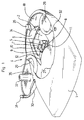
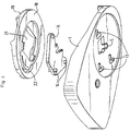
- the first embodiment of Figures 1 and 2, and the second embodiment of Figures 3 and 4 have the same elements functional and the same kinematics, from the point of view of lens bending Intraocular. They differ only in the material used (synthetic material in Figures 1 and 2, metal such as aluminum in Figures 3 and 4) and thereby that the first embodiment has a hinged cover 30, and can make packaging office for intraocular lens 3.
- the folding device comprises a frame 1 defining a bottom 2 for receiving an intraocular lens 3 to be folded in order to its implantation in the eye of a patient.
- the frame 1 is generally flat and has shapes and dimensions which are preferably adapted to allow the gripping the device in one hand, the other hand being used to actuate maneuvering means 4 mounted on the frame 1 for folding the lens intraocular 3.
- the frame 1 and the bottom 2 are assumed extend horizontally.
- the intraocular lens 3 includes an optical part 3a in flexible foldable material and two haptic handles 3b in C.
- the receiving base 2 is advantageously provided with a cylindrical recess or central bore 5, of vertical axis, facing the part optic 3a, of smaller diameter than that of the optical part 3a, to facilitate the folding and minimizing the friction of the peripheral edges of the optical part 3a on the bottom 2 during folding.
- the diameter of the recess or hole central 5 is for example of the order of 4mm.
- the bottom 2 carries two fixed studs 6, 7, arranged at least substantially 90 ° from each other around and near the recess or hole central 5.
- Each of these studs 6, 7 defines a face 8, respectively 10, which extends upward from the bottom 2, and at least substantially perpendicular to the radial direction of the recess or central bore 5 and of the optical part 3a of a lens in place on the bottom 2.
- These faces 8, 10 define two fixed folding spans 8, 10 adapted to come into contact with the periphery of the optical part 30.
- the device comprises an intermediate moving part 12 mounted and guided on the frame 1 thanks to at least one V-shaped groove 13 on the bottom 2 receiving at least one stud 14 of the intermediate movable part 12, in particular thanks to a set of grooves 13 and nipples 14.
- the bottom 2 has three V-shaped grooves 13, each having two branches, namely a first branch and a second branch forming between them an angle at less substantially equal to the angle formed between the two potential fold lines desired for the lens 3.
- the different grooves 13 (that is to say their corresponding branches) are parallel to each other.
- the moving part intermediate 12 has three studs 14 projecting downwardly to be able to slide in the three grooves 13. The intermediate moving part 12 can thus move in translation relative to the bottom 2 according to one or the other directions corresponding to the directions of the two branches of the grooves 13.
- the intermediate movable part 12 has two faces 9, respectively 11, which extend upward relative to the bottom 2.
- these faces 9, 11 extend at least substantially perpendicular to the radial direction of the recess or central drilling 5 and of the optical part 3a of a lens in place on the bottom 2.
- Each of these faces 9, 11 which moves with the part intermediate mobile 12 defines a mobile folding span 9, 11 adapted for come into contact with the periphery of the optical part 3a of the lens.
- the folding device thus comprises two pairs 8, 9 and 10, 11 of folding spans.
- the first pair 8, 9 includes a fixed folding span 8 secured to the bottom 2 and a movable folding surface 9 secured to the movable part intermediate 12, and these two folding spans 8, 9 are adapted to be able be placed in contact with the periphery of the optical part 3a of the lens 3 in place on the bottom 2 in two opposite contact zones according to a first diametrical direction 15 at least substantially parallel to the direction of first branches of V-grooves 13.
- the second pair 10, 11 includes a folding span fixed 10 secured to the bottom 2 and a movable folding surface 11 secured to the part intermediate mobile 12, and these two folding spans 10, 11 are suitable for be able to be placed in contact with the periphery of the optical part 3a of the lens 3 in place on the bottom 2 in two opposite contact zones according to a second diametrical direction 16 at least substantially perpendicular to the first diametral direction 15, this second diametral direction 16 being at less substantially parallel to the direction of the second branches of the grooves in V 13.
- the two movable folding reaches 10, 11 are arranged around the central recess or bore 5, at least substantially 90 ° from each other around and near this recess or central drilling 5.
- the two folding spans 8, 9 and 10, 11 in the same pair extend at least substantially parallel to each other and perpendicularly to the corresponding diametral direction 15, 16.
- the intermediate moving part 12 is adapted for allow the passage of a haptic loop 3b around and behind one 11 of the two movable folding seats (that of the second pair), and has a recess 17 to do this.
- the other haptic loop 3b of the lens 3 can be passed behind the stud 7 defining the fixed folding range 10 of the second pair.
- the room intermediate mobile 12 and / or the other pad 6 are adapted to prevent the passage of the haptic loops 3b behind the other folding staves 8, 9 of the first pair of folding staves. In this way, lens 3 cannot be placed only in one possible orientation relative to the bottom 2.
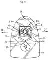
- the folding device also includes a movable member for rotary actuator 18 in the general shape of a crown which acts as a means of maneuver.
- This movable operating member 18 is hollowed out in its central part to present an access light 21 facing the lens 3 in place on the bottom 2, and has a circular external edge 19 sliding against one or several cylindrical guide face (s) 20 integral with the frame 1 adapted for receive the movable operating member 18 and guide it in rotation relative to the frame 1.
- the mobile rotary actuator 18 is connected to the movable folding surfaces 9, 11, that is to say at the intermediate movable part 12, by means of a cam mechanism 22 and contact slide 23.
- the intermediate movable part 12 carries a slide 23 which extends projecting towards the top to cooperate with a cam 22 hollowed out under the movable member 18.
- the cam shape 22 is adapted so that when the member operating mobile 18 is moved in a first direction of rotation 24 (FIG. 5b), the intermediate moving part 12 is moved in the first direction diametral 15 (the pins 14 being guided in the first branches of the grooves 13), and when it is moved in the second direction of rotation 25 (FIG. 5c) opposite the first direction of rotation 24, the intermediate movable part 12 is moved in the second diametrical direction 16 (the pins 14 being guided in the second branches of the grooves 13).
- the movable operating member 18 covers the part intermediate mobile 12 and the assembly is held in place axially by relative to the frame 1 by stops 26, 27.
- the device comprises a fixed stop 26 extending horizontally projecting above the edge of the upper face of the movable operating member 18 and, diametrically opposite to this fixed stop 26, a removable stop 27 fixed by a screw 28, so as to allow the mounting and dismounting of the movable member operating 18.
- the mobile operating member 18 comprises two maneuvering notches 29 to facilitate its manual grip and its rotary actuation.
- the first mode of actuation ( Figure 5b) of the organ operating mobile 18 in the first direction of rotation 24 has the effect of bring the mobile folding seat 9 radially closer to the first pair of folding spans, of the fixed folding span 8 of this first pair, according to the first radial direction 15, which causes the folding of the optical part 3a of the lens along a first fold line at 6 am to 12 pm at least substantially perpendicular to the first diametrical direction 15.
- the second mode of actuation ( Figure 5c) of the organ operating mobile 18 in the second direction of rotation 25 has the effect of bring the mobile folding seat 11 radially closer to the second pair of folding spans, of the fixed folding span 10 of this second pair, according to the second radial direction 16, which causes the folding of the optical part 3a of the lens along a second fold line at 3 am to 9 am at least substantially perpendicular to the second diametrical direction 16.
- the cover 30 of the folding device of the first mode of realization is articulated on the side of the frame 1, for example by a film hinge 35 formed of a thin strip of synthetic material.
- This cover 30 includes a locking pin 31 in the closed position forcibly engaged in an orifice 32 of the frame 1, and an axial extension 33 extending downwards in the closed position for maintain a lens 3 axially in place on the receiving bottom 2.
- the cover 30 in the closed position, is engaged between two straight walls 34 of the movable operating member 18, so that it then prohibits any movement untimely rotation of this movable operating member 18.
- the folding device according to the invention essentially consists of three parts movable relative to each other, namely the frame 1, the movable part intermediate 12 and the movable operating member 18.
- the folding device is formed only of two parts: the frame 1 and the movable member maneuver 18 rotatably mounted on this frame 1.
- Each movable folding span 9a, 9b, 1a, 11b is formed by an end stud of a flexible arm 36, 37 integral of frame 1 extending horizontally and perpendicular to the direction diametral according to which the staff must move.
- the first pair of folding staves includes two movable folding spans 9a, 9b and the second pair of folding spans comprises two movable folding spans 11a, 11b.
- the mobile organ of operation 18 comprises two cams 22a, 22b delimiting its central lumen 21, and adapted to come into contact simultaneously with the semi-cylindrical posterior faces 38 or 39 of the two studs forming the two folding spans 9a, 9b or 11a, 11b of the same pair of folding spans.
- One 22a of the cams one 9a, 1a of the folding spans, while the other cam 22b controls the other folding span 9b, 11b.
- the folding ranges 9a, 9b of the first pair have notches forming housing for receiving the handles haptics 3b of the lens.
- the lens 3 is maintained in place axially, that is to say carried by the frame 1, only thanks to these reception accommodation, by its haptic handles 3b.
- the movable folding spans 9a, 9b, 11a, 11b can present, as for the embodiment of FIG. 7b represented, radial inward extensions under the optical part 3a of the lens so to form, at least in part, means for receiving the lens 3 and to wear it axially.
- the movable operating member 18 has a tab 40 actuation and is guided on the frame 1 by guiding means in rotation at circular groove (s) and nipple (s).
- the cams 22a, 22b come to contact of the rear faces 38 of the studs forming the two folding spans mobiles 9a, 9b of the first pair which radially approach one of the other by bending the arms 36 which carry them.
- This displacement in flexion is comparable to a translation in the first diametrical direction 15 counts given the length of the arms 36 and the small displacement stroke induced.
- the lens 3 is then folded along a fold line from 6 am to 12 pm
- the folding device comprises a movable operating member 42 guided not in rotation on the frame 1, but in translation according to one or the other of the two directions 49, 50 perpendicular to the first diametrical direction 15 and, respectively, to the second diametrical direction 16.
- a V-shaped groove 43 is formed in the movable member of operation 42, and a stud 44 secured to the frame 1 slides in the V-shaped groove 43.
- the mobile operating member 42 includes two lights 45, 46 trapezoidal, 90 ° from each other, each defining a pair of straight cams 47, 48 converging with respect to each other for the faces posterior 38, 39 of the pads carrying the movable folding spans 9a, 9b, 11a, 11b.
- the frame 1 carries two pairs of folding spans 9a, 9b, 11a, 11b movable formed by studs at the end of flexible arms 36, 37 of the frame 1.
- Each stud also has a radial extension (FIG. 7b) towards the interior under the optical part 3a of the lens for receiving and carrying it axially.
- the radial length of these extensions is not too great for do not prevent correct folding of the lens 3.
- the two cams 47 of the first light 45 come into contact with the rear faces 38 of the pads carrying the two movable folding staves 9a, 9b of the first pair, and bring them together radially from one another in the first diametrical direction 15.
- the lens 3 is folded along a fold line from 6h to 12h.
- the two cams 48 of the second light 46 come to contact of the rear faces 39 of the pads carrying the movable folding surfaces 11a, 11b of the second pair, and bring them radially closer to each other in the second diametrical direction 16.
- the lens 3 is folded along a line folding 3 am-9am.
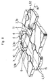
- the embodiment of Figure 8 differs from the previous one by the fact that the mobile operating member 42 is replaced by two members maneuvering mobiles 51, 52, guided in translation on the frame 1, one for each pair of folding staves.
- the device includes a first pair of folding staves 8, 9 consisting of a fixed folding 8 secured to the frame 1 and a movable folding seat 9 which is formed of the end face of the first movable operating member 51.
- the second pair consists of a fixed folding surface 10 secured to the frame 1 and a movable folding seat 11 which is formed from the end face of the second mobile operating member 52.
- Each movable operating member 51, 52 is guided in translation relative to the frame 1 in a direction which corresponds to the direction diametral 15, 16 according to which the movable folding span 9, 11 which it carries must be moved.
- the diametrical directions 15, 16, and therefore the corresponding fold lines are 90 ° from each other.
- FIG. 9 differs from that of Figures 3 and 4 by the fact that the movable rotating member 18 is replaced by a movable operating member 55 guided in translation in a single direction (i.e. along a single axis of translation), in one direction or in the other, in relation to the frame 1.
- the slide 23 of the intermediate moving part 12 is engaged in a V-shaped cam 56 of the movable operating member 55, the branches of this cam 56 being adapted so that the first direction of translation 57 of the member 55 corresponds to the first mode of actuation, that is to say to the displacement of the movable folding span 9 of the first pair for folding 6h-12h of lens 3, and so that the second direction of translation 58, opposite to first, corresponds to the second actuation mode, that is to say to the displacement of the movable folding span 11 of the second pair for a folding the lens from 3 am to 9 am.
- Figures 10 and 11 is similar to that of FIGS. 3 and 4, but comprises two intermediate movable parts 12a, 12b, defining two pairs of movable folding spans 9a, 9b, 11a, 11b.
- each intermediate movable part 12a, 12b is guided in translation on the frame 1 thanks to at least one V-shaped groove 13a, 13b at the bottom 2 of the frame 1 receiving at less a stud 14a, 14b secured, respectively, to the moving part intermediate 12a, 12b corresponding.
- a single V-shaped groove 13a, 13b is provided for each moving part 12a, 12b which is also guided by circular guide surfaces 68a, 68b of the movable operating member 18 receiving lugs 69a, 69b of the part 12a, 12b.
- the mobile operating member 18 is moreover similar to that of the mode of Figures 3 and 4, is in the form of a crown, and is guided in rotation with respect to the frame 1.
- this mobile maneuvering member 18 comprises two cams 71a, 71b recessed in its lower face 72 to receive, respectively, a contact slide 23a, 23b which extends projecting towards the top of each intermediate moving part 12a, 12b.
- Each pair of movable folding spans 9a, 9b and 11a, 11b comprises a first bearing 9a, 11a integral with the first movable part intermediate 12a, and a second bearing 9b, 11b secured to the second part intermediate mobile 12b.
- the shape of the cams 71a, 71b of the movable member of operation 18 and means 13a, 14a, 13b, 14b for guiding the moving parts intermediaries 12a, 12b relative to the frame 1 are adapted so that when the movable operating member 18 is moved in a first direction of rotation, the two intermediate moving parts 12a, 12b are displaced in translation in approaching each other in the same first diametrical direction, the movable folding spans 9a, 9b of a first pair approaching one of the other, the pins 14a, 14b being guided in the first branches, parallel one from the other, grooves 13a, 13b, and, when the movable operating member 18 is moved in the second direction of rotation opposite to the first, the parts intermediate mobiles 12a, 12b are moved in translation while approaching from each other in the same second diametrical direction distinct from the first, the movable folding spans 11a, 11b of a second pair are approaching one from the other, the pins 14a, 14b being guided in the second branches, parallel to
- the mobile operating member 18 covers the two intermediate moving parts 12a, 12b and is held in place axially by relative to the frame 1 thanks to the stops 26, 27.
- the bottom 2 comprises a central recess 5 for receiving the lens to be folded, and reception accommodation 70 haptic loops.
- Figures 10 and 11 is therefore similar to that of FIGS. 3 and 4, and is essentially only distinguished therefrom by the fact that fixed folding spans 8, 10 of FIGS. 3 and 4 are replaced by movable folding spans 9b, 11b secured to a second movable part intermediate 12b.
- the device essentially consists of four moving parts, one per compared to the others, namely the frame 1, the two intermediate moving parts 12a, 12b, and the mobile operating member 18.
- the invention may be subject to other variants of production.
- certain characteristics of the different variants may be combined with each other.
- the invention is also applicable for folding lenses intraoculars with haptic parts which are not C-handles.
Landscapes
- Health & Medical Sciences (AREA)
- Ophthalmology & Optometry (AREA)
- Cardiology (AREA)
- Oral & Maxillofacial Surgery (AREA)
- Transplantation (AREA)
- Engineering & Computer Science (AREA)
- Biomedical Technology (AREA)
- Heart & Thoracic Surgery (AREA)
- Vascular Medicine (AREA)
- Life Sciences & Earth Sciences (AREA)
- Animal Behavior & Ethology (AREA)
- General Health & Medical Sciences (AREA)
- Public Health (AREA)
- Veterinary Medicine (AREA)
- Prostheses (AREA)
Abstract
Description
L'invention concerne un dispositif de pliage d'une lentille intraoculaire à partie optique souple avant son implantation à l'état plié par passage au travers d'une incision de faible dimension (classiquement de 3 à 4 mm) ménagée dans l'oeil (en général dans la cornée).The invention relates to a device for folding a lens. intraocular with flexible optical part before implantation in the folded state by passage through a small incision (conventionally from 3 to 4 mm) formed in the eye (usually in the cornea).
Les lentilles intraoculaires à partie optique souple présentent l'avantage de pouvoir être pliées avant d'être introduites dans l'oeil, ce qui permet de les passer dans une incision de faible dimension. Après la mise en place dans l'oeil, la partie optique se déplie et reprend sa forme initiale.Intraocular lenses with flexible optical part have the advantage of being able to be folded before being introduced into the eye, this which allows them to pass through a small incision. After the implementation placed in the eye, the optical part unfolds and resumes its initial shape.
Les lentilles intraoculaires qui peuvent être pliées ont une partie optique en un matériau souple qui peut être choisi notamment parmi les élastomères de polyuréthane, les élastomères de silicone, les gels synthétiques ou organiques (hydrogel, PMMA et/ou HEMA hydratés...).Intraocular lenses that can be folded have a optical part made of a flexible material which can be chosen in particular from polyurethane elastomers, silicone elastomers, synthetic gels or organic (hydrated hydrogel, PMMA and / or HEMA ...).
Les lentilles intraoculaires comportent en outre une partie haptique de fixation à la paroi interne de l'oeil qui peut être soit formée du même matériau que la partie optique, soit au contraire formée d'anses haptiques en un autre matériau, par exemple en PMMA, rapportées sur la partie optique.The intraocular lenses also have a part haptic attachment to the inner wall of the eye which can either be formed of the same material that the optical part, on the contrary is formed of haptic loops in a other material, for example PMMA, attached to the optical part.
Certaines lentilles intraoculaires à partie optique souple peuvent être pliées, au choix du chirurgien, selon l'une ou l'autre de plusieurs lignes de pliage distinctes, choisie notamment en fonction de la forme de la lentille, de son site ou de son mode d'implantation, ou de l'habitude du chirurgien.Certain intraocular lenses with flexible optical part can be folded, at the surgeon's choice, according to one or other of several separate fold lines, chosen in particular according to the shape of the lens, its site or its mode of implantation, or the habit of surgeon.
Ainsi, les lentilles intraoculaires comprenant deux anses haptiques courbes dites en "C" peuvent être pliées globalement selon l'un ou l'autre de deux modes de pliage.Thus, intraocular lenses comprising two handles haptic curves called "C" can be folded globally according to one or the other of two folding modes.
Dans le premier mode de pliage, dit 6h-12h, la partie optique est pliée selon une ligne de pliage diamétrale dont les prolongements au-delà de la partie optique coupent la partie d'extrémité libre de chaque anse haptique.In the first folding mode, called 6 a.m. to 12 p.m., the part optic is folded along a diametrical fold line whose extensions beyond of the optical part cut the free end part of each handle haptic.
Une fois la lentille pliée, celle-ci présente les deux anses haptiques qui s'étendent longitudinalement à l'opposé l'une de l'autre de la partie optique repliée. L'implantation s'effectue alors en deux étapes. Dans une première étape, le chirurgien tenant une pince entre les mors desquels la partie optique repliée est serrée, introduit la première anse haptique puis la partie optique dans l'oeil (dans le sac capsulaire pour une opération de la cataracte), puis desserre la pince pour libérer la partie optique. Dans une deuxième étape, le chirurgien serre dans la pince la deuxième anse haptique qui s'étend encore à travers l'incision, et l'introduit dans l'oeil.Once the lens is folded, it presents the two handles haptics that extend longitudinally opposite each other from the part folded optics. The implementation is then carried out in two stages. In first step, the surgeon holding pliers between the jaws of which the part folded optic is tight, introduces the first haptic loop then the part optic in the eye (in the capsular bag for a cataract operation), then loosens the clamp to release the optical part. In a second step, the surgeon squeezes the second haptic loop which still extends to through the incision, and introduces it into the eye.
Ce premier mode de pliage présente l'avantage d'être relativement facile à exécuter. Mais il nécessite deux étapes d'implantation et deux passages de la pince à travers l'incision. L'opération est donc relativement longue, et ces passages répétés à travers l'incision sont un facteur de risques pour le patient.This first folding method has the advantage of being relatively easy to execute. But it requires two stages of implantation and two passes of the forceps through the incision. The operation is therefore relatively long, and these repeated passages through the incision are a risk factor for the patient.
Dans le deuxième mode de pliage, dit 3h-9h, la partie optique est pliée selon une ligne de pliage diamétrale dont les prolongements au-delà de la partie optique ne coupent pas les anses haptiques. Une fois la lentille pliée, celle-ci présente les deux anses haptiques qui se chevauchent et se croisent, du même côté de la partie optique repliée. L'implantation peut alors s'effectuer en une seule étape, en introduisant tout d'abord les extrémités libres des deux anses haptiques, puis, après une rotation, la partie optique, à travers l'incision.In the second folding mode, called 3h-9h, the part optic is folded along a diametrical fold line whose extensions beyond of the optical part do not cut the haptic handles. Once the lens folded, it presents the two haptic handles which overlap and intersect, on the same side of the folded optical part. The implantation can then be carried out in a single step, by first introducing the free ends of the two handles haptics, then, after a rotation, the optical part, through the incision.
Avec ce deuxième mode de pliage, l'opération d'implantation est plus rapide, mais beaucoup plus délicate, car le chirurgien doit contrôler le bon passage et le positionnement correct de la lentille dans l'incision, et lors du dépliage de la partie optique, dans l'oeil. En outre, il peut arriver que les anses haptiques, présentées dans l'incision avec leur extrémité libre vers l'avant, butent sur une paroi oculaire, ce qui peut entraíner des lésions de l'oeil, voire même une cassure d'une anse haptique.With this second folding mode, the operation implantation is faster, but much more delicate, because the surgeon must check the correct passage and the correct positioning of the lens in the incision, and during the unfolding of the optical part, in the eye. In addition, it may happen that haptic handles, presented in the incision with their free end forward, abut on an eye wall, which can lead to eye damage or even even a break in a haptic loop.
Dès lors, aucun mode de pliage ne l'emporte sur l'autre, et les inventeurs ont en fait constaté que, pour une même lentille intraoculaire, il existe aussi bien des chirurgiens qui préconisent et utilisent le premier mode de pliage 6h-12h, et d'autres chirurgiens qui préconisent et utilisent le deuxième mode de pliage 3h-9h. En outre, il a été constaté que le mode de pliage retenu peut varier selon la personnalité du chirurgien, c'est-à-dire selon son goût ou ses habitudes, mais aussi, pour un même chirurgien, selon les cas d'opérations chirurgicales à traiter, de sorte qu'il n'est pas possible de savoir, à l'avance, le mode de pliage que le chirurgien retiendra pour une opération.Therefore, no folding mode prevails over the other, and the inventors have in fact found that, for the same intraocular lens, it There are also surgeons who recommend and use the first mode of folding 6 am-12pm, and other surgeons who advocate and use the second folding mode 3h-9h. In addition, it was found that the folding method adopted can vary according to the personality of the surgeon, that is to say according to his taste or habits, but also, for the same surgeon, depending on the case of operations to be treated, so it is not possible to know, in advance, the folding mode that the surgeon will use for an operation.
US-5 290 293 décrit une pince de pliage en une seule pièce comprenant des logements de réception de l'implant, et une paire de portées de pliage qui se rapprochent sensiblement en translation selon une direction diamétrale de la lentille lorsqu'on actionne des poignées de manoeuvre reliées entre elles par une portion souple formant charnière. Avec ce dispositif, la lentille intraoculaire une fois placée dans les logements de réception ne peut être pliée que selon une seule ligne de pliage perpendiculaire à ladite direction diamétrale, uniquement selon le mode de pliage 6h-12h. En outre, la lentille doit tout d'abord être manipulée pour être mise en place dans les logements de réception de la pince en vue de son pliage.US-5,290,293 describes a one-piece folding pliers comprising implant receiving housings, and a pair of folding which approximate substantially in translation in a direction diametral of the lens when actuating connected operating handles between them by a flexible portion forming a hinge. With this device, the lens intraocular once placed in the receptacles can not be folded that along a single fold line perpendicular to said diametrical direction, only according to the folding mode from 6 am to 12 noon. In addition, the lens must first be manipulated to be placed in the receiving housing of the clamp for folding.
US-5 139 501 décrit un dispositif de pliage comprenant une portée de pliage fixe sur un bâti, et une portée de pliage formée à l'extrémité d'un coulisseau monté mobile en translation par rapport au bâti, avec des plots d'attache des anses haptiques. Ce dispositif permet un pliage uniquement selon le mode de pliage 3h-9h. En outre, il est à noter que le coulisseau est guidé en translation vers la lentille dans une glissière en queue d'aronde, de sorte que les éventuelles poussières d'usure résultant du frottement des pièces lors de ce déplacement tendent à être emportées vers la lentille, avec le risque de la salir avant l'implantation.US-5 139 501 describes a folding device comprising a fixed folding span on a frame, and a folding span formed at the end of a slide mounted movable in translation relative to the frame, with studs attachment of haptic loops. This device allows folding only according to the folding mode 3h-9h. In addition, it should be noted that the slide is guided in translation towards the lens in a dovetail slide, so that the any wear dust resulting from the friction of the parts during this displacement tend to be carried towards the lens, with the risk of dirtying it before implantation.
Ces dispositifs de pliage ne connaissent qu'un faible succès commercial. En effet, lorsqu'ils sont proposés conjointement avec la lentille (par exemple comme emballage de la lentille placée en usine dans le dispositif), le chirurgien ne peut utiliser la lentille qu'avec le mode de pliage du dispositif de pliage correspondant. Il est donc nécessaire soit de prévoir, avant l'achat, le mode pliage retenu, ce qui est rarement possible, soit de constituer des stocks avec chaque type de dispositif de pliage. Par ailleurs, si le dispositif de pliage est proposé indépendamment de la lentille, des manipulations à risque sont nécessaires pour placer la lentille dans le dispositif de pliage, ce qui augmente le temps nécessaire à l'opération et les risques de salissure et de détérioration de la lentille.These folding devices have had little success commercial. Indeed, when they are offered in conjunction with the lens (for example example as packaging of the lens placed in the device in the factory), the surgeon can only use the lens with the folding mode of the corresponding folding. It is therefore necessary either to provide, before the purchase, the mode folding retained, which is rarely possible, either to build up stocks with each type of folding device. In addition, if the folding device is offered independently of the lens, risky manipulations are necessary to place the lens in the bending device, which increases the time required for the operation and the risk of soiling and deterioration of the lens.
US-5.281.227 décrit un dispositif de pliage de lentille souple comprenant un bâti, un organe plieur monodirectionnel comprenant une paire de mâchoires de pliage portées par des longerons souples élastiques de cet organe plieur monté rotatif sur le bâti et dissociable du bâti, et un capot. Pour plier la lentille en place entre les mâchoires de l'organe plieur, on ôte le capot, puis on place l'organe plieur selon l'orientation souhaitée par pivotement par rapport au bâti, le bâti empêchant la lentille de pivoter sur son support, puis on dissocie l'organe plieur du bâti, la lentille restant en place entre les mâchoires de l'organe plieur, puis on insère une pince de préhension de la lentille entre les mâchoires de l'organe plieur, puis on rapproche les deux mâchoires l'une vers l'autre par déformation élastique des longerons. Ce dispositif présente notamment l'inconvénient de nécessiter un glissement du support de lentilles de l'organe plieur par rapport à la lentille lors du pivotement d'orientation de l'organe plieur, au risque de détériorer l'état de surface de la partie optique, particulièrement sensible, de la lentille. De surcroít, le pliage de la lentille requiert un grand nombre de manipulations dont certaines sont relativement délicates, de la part du chirurgien. En outre, en cas de difficulté lors du pliage, la lentille risque de chuter à terre et être définitivement perdue. Egalement, le chirurgien ne peut pas laisser l'organe plieur dans une position intermédiaire de pliage compte tenu de l'élasticité des longerons. Et, l'action du chirurgien sur les longerons se retrouve directement, sans aucune démultiplication, sur les mâchoires de pliage et sur la lentille de sorte que le pliage ne peut pas être réalisé progressivement et précisément. La qualité du pliage est donc étroitement liée à l'habileté du chirurgien.US-5,281,227 describes a lens folding device flexible comprising a frame, a monodirectional folding member comprising a pair of folding jaws carried by flexible elastic beams of this type folding member rotatably mounted on the frame and separable from the frame, and a cover. For bend the lens in place between the jaws of the folding member, remove the cover, then the folding member is placed in the desired orientation by pivoting by compared to the frame, the frame preventing the lens from pivoting on its support, then we dissociates the folding member from the frame, the lens remaining in place between the jaws of the folding organ, then insert a gripper for gripping the lens between the jaws of the folding organ, then the two jaws are brought together, one towards the other by elastic deformation of the side members. This device presents in particular the disadvantage of requiring a sliding of the lens support of the organ folding with respect to the lens during the pivoting of orientation of the folding member, at the risk of deteriorating the surface condition of the optical part, particularly sensitive, from the lens. In addition, the folding of the lens requires a large number of manipulations, some of which are relatively delicate, on the part of the surgeon. In addition, in case of difficulty during folding, the lens may fall down and be permanently lost. Also, the surgeon cannot leave the folding member in an intermediate folding position taking into account the elasticity of the side members. And, the action of the surgeon on the side rails is found directly, without any reduction, on the folding jaws and on the lens so that folding cannot be done gradually and precisely. The quality of the folding is therefore closely linked to the skill of the surgeon.
L'invention vise donc à pallier ces inconvénients en proposant un dispositif de pliage d'une lentille intraoculaire qui permette, sans manipulation préalable de la lentille par rapport au dispositif, de plier la lentille selon l'un ou l'autre de plusieurs modes de pliage correspondant à des lignes de pliage diamétrales distinctes, et ce au choix du chirurgien immédiatement avant l'opération d'implantation. The invention therefore aims to overcome these drawbacks by proposing a device for folding an intraocular lens which allows, without prior manipulation of the lens relative to the device, to bend the lens according to one or other of several folding modes corresponding to lines of separate diametral folding, at the choice of the surgeon immediately before the implantation operation.
L'invention vise ainsi en particulier à proposer un dispositif de pliage qui permette de réaliser le pliage d'une lentille intraoculaire à anses haptiques en C, au choix du chirurgien immédiatement avant l'opération d'implantation, sans manipulation préalable de la lentille par rapport au dispositif, soit selon un mode de pliage 6h-12h, soit selon un mode de pliage 3h-9h.The invention thus aims in particular to propose a device of folding which allows the folding of an intraocular lens with handles haptics in C, at the surgeon's choice immediately before the operation implantation, without prior manipulation of the lens relative to the device, either according to a 6 am to 12 noon folding mode, or according to a 3 am to 9 am folding mode.
L'invention vise également à proposer un tel dispositif de pliage qui soit simple et peu coûteux.The invention also aims to propose such a device for folding that is simple and inexpensive.
L'invention vise plus particulièrement à proposer des modes de réalisation d'un tel dispositif de pliage dans lesquels il est constitué d'un nombre minimum de pièces distinctes, notamment d'au plus quatre pièces mobiles l'une par rapport à l'autre.The invention aims more particularly to propose embodiments of such a folding device in which it is made a minimum number of separate pieces, including at most four pieces movable relative to each other.
L'invention vise aussi, et plus particulièrement, à proposer des modes de réalisation d'un tel dispositif de pliage qui présentent des risques limités de salissure et de détérioration de la lentille au cours du pliage.The invention also aims, and more particularly, to propose embodiments of such a folding device which present risks limited soiling and deterioration of the lens during folding.
L'invention vise aussi, et plus particulièrement, à proposer des modes de réalisation d'un tel dispositif de pliage qui soient d'usage simple et immédiatement compréhensible, notamment qui permettent de choisir le mode de pliage facilement, rapidement, ct sans risque d'erreur.The invention also aims, and more particularly, to propose embodiments of such a folding device which are simple to use and immediately understandable, in particular which allow to choose the mode of folds easily, quickly, and without risk of error.
L'invention vise aussi, et plus particulièrement, à proposer des mode de réalisation d'un tel dispositif de pliage dont la manoeuvre soit aisée et rapide, et avec lequel le pliage peut être exécuté progressivement, lentement et avec précision sans nécessiter une habileté particulière de la part du chirurgien. A ce titre, l'invention vise plus particulièrement à proposer des modes de réalisation d'un tel dispositif de pliage dans lesquels le mouvement imparti par le chirurgien sur chaque organe mobile de manoeuvre est démultiplié, la course de déplacement de la portée de pliage mobile correspondante étant réduite par rapport à celle de l'organe mobile de manoeuvre.The invention also aims, and more particularly, to propose embodiments of such a folding device which is easy to maneuver and fast, and with which folding can be performed gradually, slowly and precisely without requiring any special skill on the part of the surgeon. AT As such, the invention aims more particularly to propose embodiments of such a folding device in which the movement imparted by the surgeon on each movable operating member is multiplied, the stroke of displacement of the corresponding movable folding span being reduced by compared to that of the mobile operating member.
L'invention vise aussi, et plus particulièrement, à proposer des modes de réalisation d'un tel dispositif de pliage dans lesquels il puisse servir d'emballage de la lentille intraoculaire et être stérilisé. The invention also aims, and more particularly, to propose embodiments of such a folding device in which it can be used packaging of the intraocular lens and be sterilized.
Pour ce faire, l'invention concerne un dispositif de pliage d'une lentille intraoculaire à partie optique souple avant son implantation, comprenant:
- des moyens de réception de la lentille,
- au moins une paire de portées de pliage adaptées pour pouvoir être placées au contact de la partie optique de la lentille en deux zones de contact opposées selon une même direction diamétrale,
- des moyens de manoeuvre reliés à au moins une portée de pliage et adaptés, lorsqu'ils sont actionnés, pour en commander un déplacement vers une autre portée de pliage d'une même paire de portées de pliage,
- selon un premier mode d'actionnement des moyens de manoeuvre, deux portées de pliage viennent au contact de la partie optique de la lentille en deux zones de contact opposées selon une première direction diamétrale, pour un pliage selon une première ligne de pliage,
- selon au moins un deuxième mode d'actionnement des moyens de manoeuvre, deux portées de pliage viennent au contact de la partie optique de la lentille en deux zones de contact opposées selon une deuxième direction diamétrale distincte de la première direction diamétrale, pour un pliage selon une deuxième ligne de pliage distincte de la première ligne de pliage,
- means for receiving the lens,
- at least one pair of folding spans adapted to be able to be placed in contact with the optical part of the lens in two opposite contact zones in the same diametral direction,
- maneuvering means connected to at least one folding span and adapted, when actuated, to control a displacement thereof towards another folding span of the same pair of folding spans,
- according to a first mode of actuation of the maneuvering means, two folding ranges come into contact with the optical part of the lens in two opposite contact zones in a first diametrical direction, for folding along a first fold line,
- according to at least one second mode of actuation of the maneuvering means, two folding surfaces come into contact with the optical part of the lens in two opposite contact zones in a second diametrical direction distinct from the first diametrical direction, for folding according to a second fold line separate from the first fold line,
Avantageusement et selon l'invention, notamment lorsque la lentille intraoculaire est du type comprenant deux anses haptiques en C, (dans tout le texte, on désigne par cette expression, des anses haptiques courbes déformables en flexion reliées à la périphérie de la partie optique par l'une de leurs extrémités et ayant une autre extrémité libre, les deux anses étant globalement de formes symétriques l'une de l'autre par rapport à l'axe optique de la partie optique), la première direction diamétrale et la deuxième direction diamétrale forment entre elles un angle compris entre 60° et 120°, de sorte que la lentille peut être pliée selon l'une ou l'autre de deux lignes de pliage formant entre elles un angle compris entre 60° et 120°.Advantageously and according to the invention, in particular when the intraocular lens is of the type comprising two haptic loops in C, (in all the text, we designate by this expression, curved haptic handles flexibly deformable connected to the periphery of the optical part by one of their ends and having another free end, the two handles being globally symmetrical to each other with respect to the optical axis of the optical part), the first diametrical direction and the second direction diametral form an angle between them between 60 ° and 120 °, so that the lens can be folded in either of two fold lines forming between them an angle between 60 ° and 120 °.
Dans une variante, avantageusement et selon l'invention, le dispositif de pliage comprend :
- un bâti comportant les moyens de réception de la lentille,
- au moins une paire de portées de pliage adaptées pour pouvoir être placées radialement au contact de la périphérie de la partie optique de la lentille en deux zones de contact diamétralement opposées, l'une au moins des deux portées de pliage, dite portée de pliage mobile d'une paire de portées de pliage, étant montée par rapport au bâti de façon à pouvoir être rapprochée de l'autre portée de pliage de cette paire de portées de pliage,
- a frame comprising the means for receiving the lens,
- at least one pair of folding spans adapted to be able to be placed radially in contact with the periphery of the optical part of the lens in two diametrically opposite contact zones, at least one of the two folding spans, known as mobile folding span a pair of folding spans, being mounted relative to the frame so that it can be brought closer to the other folding span of this pair of folding spans,
Selon une caractéristique avantageuse de l'invention, le dispositif de pliage est caractérisé en ce qu'il comprend:
- une première paire de portées de pliage adaptées pour pouvoir être placées au contact de la périphérie de la partie optique de la lentille en deux zones de contact opposées selon la première direction diamétrale, et produire sous l'effet de l'actionnement d'au moins un organe mobile de manoeuvre selon le premier mode d'actionnement, un pliage de la lentille selon la première ligne de pliage,
- au moins une deuxième paire de portées de pliage, distincte de la première paire de portées de pliage, les portées de pliage de cette deuxième paire étant adaptées pour pouvoir être placées au contact de la périphérie de la partie optique de la lentille en deux zones de contact opposées selon la deuxième direction diamétrale et produire, sous l'effet de l'actionnement d'au moins un organe mobile de manoeuvre selon le deuxième mode d'actionnement, un pliage de la lentille selon la deuxième ligne de pliage distincte de la première ligne de pliage.
- a first pair of folding spans adapted to be able to be placed in contact with the periphery of the optical part of the lens in two opposite contact zones in the first diametrical direction, and to produce under the effect of the actuation of at least a mobile maneuvering member according to the first actuation mode, a folding of the lens along the first folding line,
- at least a second pair of folding spans, distinct from the first pair of folding spans, the folding spans of this second pair being adapted so that they can be placed in contact with the periphery of the optical part of the lens in two zones of opposite contacts in the second diametrical direction and produce, under the effect of the actuation of at least one movable operating member according to the second actuation mode, a folding of the lens according to the second folding line distinct from the first fold line.
Dans un mode de réalisation et selon l'invention, le dispositif de pliage est caractérisé en ce que les moyens de manoeuvre comprennent au moins deux organes mobiles de manoeuvre, dont l'un est relié à au moins une première portée de pliage mobile d'une première paire de portées de pliage, et dont l'autre est relié à au moins une deuxième portée de pliage mobile d'une deuxième paire de portées de pliage.In one embodiment and according to the invention, the folding device is characterized in that the operating means comprise at least two mobile operating members, one of which is connected to at least a first movable folding span of a first pair of spans folding, and the other of which is connected to at least one second folding span mobile of a second pair of folding staves.
Dans un autre mode de réalisation, avantageusement et selon l'invention, le dispositif de pliage est caractérisé en ce que les moyens de manoeuvre comprennent un organe mobile de manoeuvre relié à au moins une première portée de pliage mobile de la première paire de portées de pliage et à au moins une deuxième portée de pliage mobile de la deuxième paire de portées de pliage, cet organe mobile de manoeuvre étant adapté pour pouvoir être actionné soit selon le premier mode d'actionnement, soit selon le deuxième mode d'actionnement.In another embodiment, advantageously and according to the invention, the folding device is characterized in that the means for maneuver comprises a mobile maneuvering member connected to at least one first mobile folding span of the first pair of folding staves and at minus a second movable folding span of the second pair of spans of folding, this movable operating member being adapted to be able to be actuated either according to the first mode of actuation, or according to the second mode actuating.
Avantageusement et selon l'invention, le dispositif de pliage est caractérisé en ce que l'organe mobile de manoeuvre est monté rotatif par rapport au bâti, en ce que le premier mode d'actionnement correspond à un déplacement en rotation de l'organe mobile de manoeuvre dans un premier sens de rotation, et en ce que le deuxième mode d'actionnement correspond à un déplacement en rotation de l'organe mobile de manoeuvre dans le deuxième sens de rotation opposé au premier sens de rotation. En variante ou en combinaison, le dispositif de pliage est caractérisé en ce que l'organe mobile de manoeuvre est monté par rapport au bâti de façon à pouvoir être déplacé selon au moins deux directions de translation distinctes dont l'une correspond au premier mode d'actionnement alors que l'autre correspond au deuxième mode d'actionnement. Dans une autre variante, ou en combinaison, le dispositif de pliage est caractérisé en ce que l'organe mobile de manoeuvre est monté par rapport au bâti de façon à pouvoir être déplacé selon au moins une direction de translation et selon au moins deux sens opposés selon cette direction de translation, dont l'un correspond au premier mode d'actionnement alors que l'autre correspond au deuxième mode d'actionnement. Advantageously and according to the invention, the device for folding is characterized in that the movable operating member is rotatably mounted with respect to the frame, in that the first actuation mode corresponds to a rotational movement of the movable operating member in a first direction rotation, and in that the second actuation mode corresponds to a rotational movement of the movable operating member in the second direction opposite to the first direction of rotation. As a variant or in combination, the folding device is characterized in that the movable maneuvering member is mounted relative to the frame so that it can be moved in at least two separate translation directions, one of which corresponds to the first mode actuation while the other corresponds to the second actuation mode. In another variant, or in combination, the folding device is characterized in that the movable operating member is mounted relative to the frame so as to be able to be moved in at least one direction of translation and according to minus two opposite directions in this direction of translation, one of which corresponds to the first actuation mode while the other corresponds to second actuation mode.
Il est à noter que rien n'empêche de prévoir que l'organe mobile de manoeuvre soit monté rotatif et coulissant, c'est-à-dire avec des composantes de déplacement combinées en rotation et en translation.It should be noted that nothing prevents the provision that the organ maneuvering mobile is mounted rotatable and sliding, that is to say with displacement components combined in rotation and translation.
Par ailleurs, avantageusement et selon l'invention, le dispositif de pliage est caractérisé en ce qu'une première portée de pliage mobile de la première paire de portées de pliage et une deuxième portée de pliage mobile de la deuxième paire de portées de pliage sont solidaires d'une seule et même pièce mobile intermédiaire montée et guidée par rapport au bâti et reliée à l'organe mobile de manoeuvre de façon à pouvoir être entraínée en déplacement sous l'effet de l'actionnement de cet organe mobile de manoeuvre selon l'un ou l'autre des modes d'actionnementFurthermore, advantageously and according to the invention, the folding device is characterized in that a first movable folding span of the first pair of folding spans and a second movable folding span of the second pair of folding spans are integral with one and the same intermediate moving part mounted and guided relative to the frame and connected to the movable operating member so as to be able to be driven on the move under the effect of the actuation of this movable operating member according to one or the other of the actuation modes
Egalement, dans les différents modes de réalisation, avantageusement et selon l'invention, un organe mobile de manoeuvre est relié à chaque portée de pliage mobile dont il commande les déplacements par l'intermédiaire d'un système à came et coulisseau de contact. Ainsi, le mouvement d'actionnement du praticien sur cet organe de manoeuvre mobile pourra avoir une course plus grande que celle du déplacement de la portée de pliage mobile.Also, in the different embodiments, advantageously and according to the invention, a mobile operating member is connected to each mobile folding span, the movements of which it controls through a contact cam and slide system. So the actuation movement of the practitioner on this movable operating member may have a greater stroke than that of the displacement of the range of mobile folding.
En outre, dans certains modes de réalisation, avantageusement et selon l'invention, chaque paire de portées de pliage comprend une portée de pliage fixe par rapport au bâti. Egalement, dans certains modes de réalisation, avantageusement et selon l'invention, chaque portée de pliage mobile est montée par rapport au bâti, de façon à pouvoir être mobile au moins sensiblement en translation, notamment selon une direction diamétrale correspondante.Additionally, in some embodiments, advantageously and according to the invention, each pair of folding spans includes a fixed folding span relative to the frame. Also, in some embodiments, advantageously and according to the invention, each scope of movable folding is mounted relative to the frame, so that it can be movable less substantially in translation, in particular in a diametrical direction corresponding.
En outre, avantageusement et selon l'invention, le dispositif de pliage est caractérisé en ce que les moyens de réception sont adaptés pour recevoir la lentille intraoculaire orientée, notamment par rapport au bâti, selon une et une seule direction possible. En particulier, les moyens de réception comportent, avantageusement et selon l'invention, des logements de réception de la partie haptique de la lentille -notamment des anses haptiques en C-. Les moyens de réception peuvent être formés, en totalité ou en partie, par les portées de pliage elles-mêmes (fixe(s) ou mobile(s)).In addition, advantageously and according to the invention, the device of folding is characterized in that the receiving means are adapted to receive the oriented intraocular lens, in particular relative to the frame, according to one and only one direction possible. In particular, the means of reception advantageously and according to the invention, include housing for receiving the haptic part of the lens -in particular haptic handles in C-. The receiving means can be formed, in whole or in part, by the scopes folding themselves (fixed (s) or mobile (s)).
Il est à noter que la lentille étant en place dans les moyens de réception selon son orientation prédéterminée, le chirurgien n'a pas à manipuler la lentille, avec une pince ou autrement, pour choisir le mode de pliage. Il lui suffit en effet d'actionner les moyens de manoeuvre du dispositif de pliage selon le mode d'actionnement approprié au pliage retenu.It should be noted that the lens being in place in the means of reception according to his predetermined orientation, the surgeon does not have to manipulate the lens, with pliers or otherwise, to choose the mode of folding. It suffices for him to activate the operating means of the folding according to the actuation mode appropriate to the selected folding.
Par ailleurs, avantageusement et selon l'invention, le dispositif de pliage est caractérisé en ce qu'il constitue un emballage d'une lentille intraoculaire et comprend un capot refermé sur la lentille en place dans les moyens de réception, ce capot étant adapté pour pouvoir être ouvert pour permettre l'accès à la lentille. Avantageusement et selon l'invention, ce capot est adapté pour avoir aussi pour fonction de maintenir la lentille en place dans les moyens de réception perpendiculairement au plan de la partie optique, c'est-à-dire selon l'axe optique.Furthermore, advantageously and according to the invention, the folding device is characterized in that it constitutes a package of a lens intraocular and includes a cover closed over the lens in place in the receiving means, this cover being adapted to be able to be opened for allow access to the lens. Advantageously and according to the invention, this cover is adapted to also have the function of holding the lens in place in the reception means perpendicular to the plane of the optical part, that is to say along the optical axis.
En outre, avantageusement et selon l'invention, le capot est adapté pour, en position refermée sur la lentille, interdire tout déplacement intempestif des moyens de manoeuvre, et, en position ouverte, autoriser l'actionnement des moyens de manoeuvre selon l'un ou l'autre des modes d'actionnement.In addition, advantageously and according to the invention, the cover is suitable for, in the closed position on the lens, preventing any movement untimely maneuvering means, and, in the open position, authorize actuation of the operating means according to one or the other of the modes actuating.
L'invention s'étend aussi à un dispositif de pliage caractérisé en combinaison par tout ou partie des caractéristiques mentionnées ci-dessus ou ci-après.The invention also extends to a folding device characterized in combination by all or some of the characteristics mentioned above or below.
D'autres buts, caractéristiques et avantages de l'invention apparaítront à la lecture de la description suivante qui se réfère aux figures annexées dans lesquelles :
- les figures 1
et 2 sont des vues schématiques en perspective d'un dispositif de pliage selon un premier mode de réalisation de l'invention réalisé en matière synthétique, illustré, respectivement, avec le capot ouvert et avec le capot fermé. - les figures 3
et 4 sont des vues schématiques en perspective éclatée de trois-quarts supérieure et, respectivement de trois-quarts inférieure, d'un dispositif de pliage selon un deuxième mode de réalisation semblable au premier mode de réalisation de l'invention, mais réalisé en métal et exempt de capot, - les figures Sa, 5b, 5c sont des vues schématiques de
dessus illustrant le dispositif de pliage des figures 3
et 4, respectivement en position initiale, en position de pliage 6h-12h, et en position de pliage 3h-9h d'une lentille intraoculaire, - les figures 6, 7a et 8 sont des vues schématiques en perspective illustrant, respectivement, trois autres modes de réalisation d'un dispositif de pliage selon l'invention, la figure 7b étant une vue schématique de dessus, à moindre échelle, du bâti du dispositif de la figure 7a,
- la figure 9 est une vue schématique de dessus illustrant un autre mode de réalisation d'un dispositif selon l'invention,
- les figures 10 et 11 sont des vues schématiques en perspective éclatée de trois-quart supérieure et, respectivement de trois-quart inférieure d'un autre mode de réalisation d'un dispositif selon l'invention.
- Figures 1 and 2 are schematic perspective views of a folding device according to a first embodiment of the invention made of synthetic material, illustrated, respectively, with the cover open and with the cover closed.
- Figures 3 and 4 are schematic exploded perspective views of three-quarter upper and, respectively three-quarter lower, of a folding device according to a second embodiment similar to the first embodiment of the invention, but made of metal and free of cover,
- Figures Sa, 5b, 5c are schematic views from above illustrating the folding device of Figures 3 and 4, respectively in the initial position, in the folding position 6h-12h, and in the folding position 3h-9h of an intraocular lens ,
- Figures 6, 7a and 8 are schematic perspective views illustrating, respectively, three other embodiments of a folding device according to the invention, Figure 7b being a schematic top view, on a smaller scale, of the frame of the device of FIG. 7a,
- FIG. 9 is a schematic top view illustrating another embodiment of a device according to the invention,
- FIGS. 10 and 11 are schematic exploded perspective views of an upper three-quarter and, respectively, of a lower three-quarter of another embodiment of a device according to the invention.
Sur les différentes figures, les mêmes repères sont utilisés pour désigner les mêmes éléments fonctionnels.In the different figures, the same references are used to designate the same functional elements.
Le premier mode de réalisation des figures 1 et 2, et le
deuxième mode de réalisation des figures 3 et 4, présentent les mêmes éléments
fonctionnels et la même cinématique, du point de vue du pliage de la lentille
intraoculaire. Ils ne diffèrent que par le matériau utilisé (matière synthétique dans
les figures 1 et 2, métal tel que l'aluminium dans les figures 3 et 4) et par le fait
que le premier mode de réalisation est doté d'un capot 30 articulé, et peut faire
office d'emballage pour la lentille 3 intraoculaire.The first embodiment of Figures 1 and 2, and the
second embodiment of Figures 3 and 4, have the same elements
functional and the same kinematics, from the point of view of lens bending
Intraocular. They differ only in the material used (synthetic material in
Figures 1 and 2, metal such as aluminum in Figures 3 and 4) and thereby
that the first embodiment has a hinged
Sur ces figures, le dispositif de pliage comporte un bâti 1
définissant un fond 2 de réception d'une lentille intraoculaire 3 à plier en vue de
son implantation dans l'oeil d'un patient. Le bâti 1 est globalement plat et présente
des formes et dimensions qui sont de préférence adaptées pour permettre la
préhension du dispositif dans une main, l'autre main servant à actionner des
moyens 4 de manoeuvre montés sur le bâti 1 pour le pliage de la lentille
intraoculaire 3. Dans la présente description, le bâti 1 et le fond 2 sont supposés
s'étendre horizontalement. La lentille intraoculaire 3 comprend une partie optique
3a en matériau souple pliable et deux anses haptiques 3b en C.In these figures, the folding device comprises a frame 1
defining a
Le fond 2 de réception est avantageusement doté d'un
évidement ou perçage central cylindrique 5, d'axe vertical, en regard de la partie
optique 3a, de diamètre inférieur à celui de la partie optique 3a, pour faciliter le
pliage et minimiser les frottements des bords périphériques de la partie optique
3a sur le fond 2 au cours du pliage. Le diamètre de l'évidement ou perçage
central 5 est par exemple de l'ordre de 4mm.The receiving
Le fond 2 porte deux plots fixes 6, 7, disposés au moins
sensiblement à 90° l'un de l'autre autour et à proximité de l'évidement ou perçage
central 5. Chacun de ces plots 6, 7 définit une face 8, respectivement 10, qui
s'étend vers le haut à partir du fond 2, et au moins sensiblement
perpendiculairement à la direction radiale de l'évidement ou perçage central 5 et
de la partie optique 3a d'une lentille en place sur le fond 2. Ces faces 8, 10
définissent deux portées de pliage fixes 8, 10 adaptées pour venir au contact de la
périphérie de la partie optique 30.The bottom 2 carries two fixed studs 6, 7, arranged at least
substantially 90 ° from each other around and near the recess or hole
central 5. Each of these studs 6, 7 defines a
Le dispositif comporte une pièce mobile intermédiaire 12
montée et guidée sur le bâti 1 grâce à au moins une rainure en V 13 du fond 2
recevant au moins un téton 14 de la pièce mobile intermédiaire 12, notamment
grâce à un ensemble de rainures 13 et tétons 14. Comme on le voit figures 3 et 4,
le fond 2 comporte trois rainures en V 13, ayant chacune deux branches, à savoir
une première branche et une deuxième branche formant entre elles un angle au
moins sensiblement égal à l'angle formé entre les deux lignes de pliage potentiel
souhaitées pour la lentille 3. Les différentes rainures 13 (c'est-à-dire leurs
branches correspondantes) sont parallèles entre elles. La pièce mobile
intermédiaire 12 comporte trois tétons 14 s'étendant en saillie vers le bas pour
pouvoir coulisser dans les trois rainures 13. La pièce mobile intermédiaire 12
peut ainsi se déplacer en translation par rapport au fond 2 selon l'une ou l'autre
des directions correspondant aux directions des deux branches des rainures 13.The device comprises an intermediate moving
La pièce mobile intermédiaire 12 présente deux faces 9,
respectivement 11, qui s'étendent vers le haut par rapport au fond 2. Lorsque la
pièce mobile intermédiaire 12 est en position initiale avant le pliage, les tétons 14
étant placés au sommet des rainures en V 13, ces faces 9, 11 s'étendent au moins
sensiblement perpendiculairement à la direction radiale de l'évidement ou
perçage central 5 et de la partie optique 3a d'une lentille en place sur le fond 2.The intermediate
Chacune de ces faces 9, 11 qui se déplace avec la pièce
mobile intermédiaire 12 définit une portée de pliage mobile 9, 11 adaptée pour
venir au contact de la périphérie de la partie optique 3a de la lentille.Each of these
Le dispositif de pliage comporte ainsi deux paires 8, 9 et
10, 11 de portées de pliage.The folding device thus comprises two
La première paire 8, 9 comprend une portée de pliage fixe
8 solidaire du fond 2 et une portée de pliage mobile 9 solidaire de la pièce mobile
intermédiaire 12, et ces deux portées de pliage 8, 9 sont adaptées pour pouvoir
être placées au contact de la périphérie de la partie optique 3a de la lentille 3 en
place sur le fond 2 en deux zones de contact opposées selon une première
direction diamétrale 15 au moins sensiblement parallèle à la direction des
premières branches des rainures en V 13.The
La deuxième paire 10, 11 comprend une portée de pliage
fixe 10 solidaire du fond 2 et une portée de pliage mobile 11 solidaire de la pièce
mobile intermédiaire 12, et ces deux portées de pliage 10, 11 sont adaptées pour
pouvoir être placées au contact de la périphérie de la partie optique 3a de la
lentille 3 en place sur le fond 2 en deux zones de contact opposées selon une
deuxième direction diamétrale 16 au moins sensiblement perpendiculaire à la
première direction diamétrale 15, cette deuxième direction diamétrale 16 étant au
moins sensiblement parallèle à la direction des deuxièmes branches des rainures
en V 13.The
En position initiale, les deux portées de pliage mobile 10,
11 sont disposées autour de l'évidement ou perçage central 5, au moins
sensiblement à 90° l'une de l'autre autour et à proximité de cet évidement ou
perçage central 5. Les deux portées de pliage 8, 9 et 10, 11 d'une même paire
s'étendent au moins sensiblement parallèles l'un de l'autre et perpendiculairement
à la direction diamétrale 15, 16 correspondante.In the initial position, the two movable folding reaches 10,
11 are arranged around the central recess or bore 5, at least
substantially 90 ° from each other around and near this recess or
La pièce mobile intermédiaire 12 est adaptée pour
permettre le passage d'une anse haptique 3b autour et derrière l'une 11 des deux
portées de pliage mobile (celle de la deuxième paire), et comporte un évidement
17 pour ce faire. L'autre anse haptique 3b de la lentille 3 peut être passée derrière
le plot 7 définissant la portée de pliage fixe 10 de la deuxième paire. La pièce
mobile intermédiaire 12 et/ou l'autre plot 6 sont adaptés pour empêcher le
passage des anses haptiques 3b derrière les autres portées de pliage 8, 9 de la
première paire de portées de pliage. De la sorte, la lentille 3 ne peut être placée
que selon une seule orientation possible par rapport au fond 2.The intermediate moving
Le dispositif de pliage comporte aussi un organe mobile de
manoeuvre 18 rotatif en forme générale de couronne qui fait office de moyen de
manoeuvre. Cet organe mobile de manoeuvre 18 est évidé en sa partie centrale
pour présenter une lumière d'accès 21 en regard de la lentille 3 en place sur le
fond 2, et présente un chant externe circulaire 19 venant glisser contre une ou
plusieurs face(s) cylindrique(s) 20 de guidage solidaires du bâti 1 adaptées pour
recevoir l'organe mobile de manoeuvre 18 et le guider en rotation par rapport au
bâti 1.The folding device also includes a movable member for
L'organe mobile de manoeuvre rotatif 18 est relié aux
portées de pliage mobiles 9, 11, c'est-à-dire à la pièce mobile intermédiaire 12,
par l'intermédiaire d'un mécanisme à came 22 et coulisseau de contact 23. Ainsi,
la pièce mobile intermédiaire 12 porte un coulisseau 23 qui s'étend en saillie vers
le haut pour coopérer avec une came 22 ménagée en creux sous l'organe mobile
de manoeuvre 18. La forme de came 22 est adaptée pour que lorsque l'organe
mobile de manoeuvre 18 est déplacé dans un premier sens de rotation 24 (figure
5b), la pièce mobile intermédiaire 12 est déplacée selon la première direction
diamétrale 15 (les tétons 14 étant guidés dans les premières branches des rainures
13), et lorsqu'il est déplacé dans le deuxième sens de rotation 25 (figure 5c)
opposé au premier sens de rotation 24, la pièce mobile intermédiaire 12 est
déplacée selon la deuxième direction diamétrale 16 (les tétons 14 étant guidés
dans les deuxièmes branches des rainures 13).The mobile
L'organe mobile de manoeuvre 18 vient coiffer la pièce
mobile intermédiaire 12 et l'ensemble est maintenu en place axialement par
rapport au bâti 1 par des butées 26, 27. The
Dans le mode de réalisation des figures 3 et 4, le dispositif
comprend une butée fixe 26 s'étendant en saillie horizontalement au-dessus de la
bordure de la face supérieure de l'organe mobile de manoeuvre 18 et,
diamétralement opposée à cette butée fixe 26, une butée amovible 27 fixée par
une vis 28, de façon à permettre le montage et le démontage de l'organe mobile
de manoeuvre 18.In the embodiment of Figures 3 and 4, the device
comprises a fixed
Dans le mode de réalisation des figures 1 et 2, les deux
butées 26, 27 sont fixes, et l'organe mobile de manoeuvre 18 est engagé en force
sous ces butées 26, 27 en matière plastique par déformation élastique.In the embodiment of Figures 1 and 2, the two
stops 26, 27 are fixed, and the
L'organe mobile de manoeuvre 18 comprend deux
échancrures de manoeuvre 29 permettant de faciliter sa prise manuelle et son
actionnement en rotation.The
Le premier mode d'actionnement (figure 5b) de l'organe
mobile de manoeuvre 18 selon le premier sens de rotation 24 a pour effet de
rapprocher radialement la portée de pliage mobile 9 de la première paire de
portées de pliage, de la portée de pliage fixe 8 de cette première paire, selon la
première direction radiale 15, ce qui entraíne le pliage de la partie optique 3a de
la lentille selon une première ligne de pliage 6h-12h au moins sensiblement
perpendiculaire à la première direction diamétrale 15.The first mode of actuation (Figure 5b) of the organ
operating mobile 18 in the first direction of
Le deuxième mode d'actionnement (figure 5c) de l'organe
mobile de manoeuvre 18 selon le deuxième sens de rotation 25 a pour effet de
rapprocher radialement la portée de pliage mobile 11 de la deuxième paire de
portées de pliage, de la portée de pliage fixe 10 de cette deuxième paire, selon la
deuxième direction radiale 16, ce qui entraíne le pliage de la partie optique 3a de
la lentille selon une deuxième ligne de pliage 3h-9h au moins sensiblement
perpendiculaire à la deuxième direction diamétrale 16.The second mode of actuation (Figure 5c) of the organ
operating mobile 18 in the second direction of
Le capot 30 du dispositif de pliage du premier mode de
réalisation est articulé sur le côté du bâti 1, par exemple par une charnière film 35
formée d'une bande mince de matériau synthétique. Ce capot 30 comporte un
téton de verrouillage 31 en position fermée engagé en force dans un orifice 32 du
bâti 1, et une extension axiale 33 s'étendant vers le bas en position fermée pour
maintenir une lentille 3 axialement en place sur le fond 2 de réception. En outre,
en position fermée, le capot 30 est engagé entre deux parois droites 34 de
l'organe mobile de manoeuvre 18, de sorte qu'il interdit alors tout déplacement
intempestif en rotation de cet organe mobile de manoeuvre 18.The
Lorsque le capot est ouvert (figure 1), l'organe mobile de
manoeuvre 18 est libéré et peut être actionné dans l'un ou l'autre des sens de
rotation 24, 25.When the cover is open (Figure 1), the movable member of
Dans les modes de réalisation des figures 1 et 2 et 3 et 4, le
dispositif de pliage selon l'invention est essentiellement constitué de trois pièces
mobiles les unes par rapport aux autres, à savoir le bâti 1, la pièce mobile
intermédiaire 12 et l'organe mobile de manoeuvre 18.In the embodiments of FIGS. 1 and 2 and 3 and 4, the
folding device according to the invention essentially consists of three parts
movable relative to each other, namely the frame 1, the movable part
intermediate 12 and the
Dans le mode de réalisation représenté figure 6, le
dispositif de pliage n'est formé que de deux pièces : le bâti 1 et l'organe mobile
de manoeuvre 18 monté rotatif sur ce bâti 1. Chaque portée de pliage mobile 9a,
9b, 1 la, 11b est formée par un plot d'extrémité d'un bras flexible 36, 37 solidaire
du bâti 1 s'étendant horizontalement et perpendiculairement à la direction
diamétrale selon laquelle la portée doit se déplacer.In the embodiment shown in FIG. 6, the
folding device is formed only of two parts: the frame 1 and the
En outre, dans ce mode de réalisation, toutes les portées de
pliage sont mobiles. La première paire de portées de pliage comprend deux
portées de pliage mobiles 9a, 9b et la deuxième paire de portées de pliage
comprend deux portées de pliage mobiles 11a, 11b. L'organe mobile de
manoeuvre 18 comporte deux cames 22a, 22b délimitant sa lumière centrale 21,
et adaptées pour venir simultanément au contact des faces postérieures semi-cylindriques
38 ou 39 des deux plots formant les deux portées de pliage 9a, 9b ou
11a, 11b d'une même paire de portées de pliage. L'une 22a des cames commande
l'une 9a, 1 la des portées de pliage, tandis que l'autre came 22b commande l'autre
portée de pliage 9b, 11b. Les portées de pliage 9a, 9b de la première paire
présentent des échancrures formant des logements de réception des anses
haptiques 3b de la lentille. Dans la variante représentée la lentille 3 est maintenue
en place axialement, c'est-à-dire portée par le bâti 1, uniquement grâce à ces
logements de réception, par ses anses haptiques 3b.Furthermore, in this embodiment, all the ranges of
folding are movable. The first pair of folding staves includes two
movable folding spans 9a, 9b and the second pair of folding spans
comprises two movable folding spans 11a, 11b. The mobile organ of
Les portées de pliage mobiles 9a, 9b, 11a, 11b peuvent présenter, comme pour le mode de réalisation de la figure 7b représenté, des extensions radiales vers l'intérieur sous la partie optique 3a de la lentille de façon à former, au moins en partie, des moyens de réception de la lentille 3 et la porter axialement.The movable folding spans 9a, 9b, 11a, 11b can present, as for the embodiment of FIG. 7b represented, radial inward extensions under the optical part 3a of the lens so to form, at least in part, means for receiving the lens 3 and to wear it axially.
L'organe mobile de manoeuvre 18 comporte une patte 40
d'actionnement et est guidé sur le bâti 1 par des moyens de guidage en rotation à
rainure(s) circulaire(s) et téton(s). Lorsque l'on actionne l'organe mobile de
manoeuvre 18 dans le premier sens de rotation 24, les cames 22a, 22b viennent au
contact des faces postérieures 38 des plots formant les deux portées de pliage
mobiles 9a, 9b de la première paire qui se rapprochent radialement l'une de
l'autre par flexion des bras 36 qui les portent. Ce déplacement en flexion est
assimilable à une translation selon la première direction diamétrale 15 compte
tenu de la longueur des bras 36 et de la faible course de déplacement induite. La
lentille 3 est alors pliée selon une ligne de pliage 6h-12hThe
Lorsque l'on actionne l'organe mobile de manoeuvre 18
dans le deuxième sens de rotation 25, les cames 22a, 22b viennent au contact des
faces 39, et les deux portées de pliage mobiles 11a, 11b se rapprochent
radialement l'une de l'autre par flexion des bras 37 qui les portent, le déplacement
étant assimilable à une translation selon la deuxième direction diamétrale 16. La
lentille 3 est pliée selon une ligne de pliage 3h-9h.When the
Dans le mode de réalisation des figures 7a et 7b, le
dispositif de pliage comporte un organe mobile de manoeuvre 42 guidé non pas
en rotation sur le bâti 1, mais en translation selon l'une ou l'autre des deux
directions 49, 50 perpendiculaires à la première direction diamétrale 15 et,
respectivement, à la deuxième direction diamétrale 16. Pour ce faire, au moins
une rainure en V 43, à deux branches à 90°, est ménagée dans l'organe mobile de
manoeuvre 42, et un téton 44 solidaire du bâti 1 coulisse dans la rainure en V 43.In the embodiment of Figures 7a and 7b, the
folding device comprises a
L'organe mobile de manoeuvre 42 comprend deux lumières
45, 46 trapézoïdales, à 90° l'une de l'autre, définissant chacune une paire de
cames droites 47, 48 convergentes l'une par rapport à l'autre pour les faces
postérieures 38, 39 des plots portant les portées de pliage mobiles 9a, 9b, 11a,
11b. The
Là encore, le bâti 1 porte deux paires de portées de pliage
9a, 9b, 11a, 11b mobiles formées par des plots à l'extrémité de bras flexibles 36,
37 du bâti 1. Chaque plot comporte aussi une extension radiale (figure 7b) vers
l'intérieur sous la partie optique 3a de la lentille pour la recevoir et la porter
axialement. La longueur radiale de ces extensions n'est pas trop importante pour
ne pas empêcher un pliage correct de la lentille 3.Again, the frame 1 carries two pairs of folding spans
9a, 9b, 11a, 11b movable formed by studs at the end of
Lorsque l'on actionne l'organe 42 selon une première
direction de translation 49 par rapport au bâti 1, les deux cames 47 de la première
lumière 45 viennent au contact des faces postérieures 38 des plots portant les
deux portées de pliage mobiles 9a, 9b de la première paire, et les rapprochent
radialement l'une de l'autre selon la première direction diamétrale 15. La lentille
3 est pliée selon une ligne de pliage 6h-12h.When the
Lorsqu'on déplace l'organe 42 selon la deuxième direction
de translation 50, les deux cames 48 de la deuxième lumière 46 viennent au
contact des faces postérieures 39 des plots portant les portées de pliage mobiles
11a, 11b de la deuxième paire, et les rapprochent radialement l'une de l'autre
selon la deuxième direction diamétrale 16. La lentille 3 est pliée selon une ligne
de pliage 3h-9h.When the
Le mode de réalisation de la figure 8 diffère du précédent
par le fait que l'organe mobile de manoeuvre 42 est remplacé par deux organes
mobiles de manoeuvre 51, 52, guidés en translation sur le bâti 1, un pour chaque
paire de portées de pliage. En outre, dans ce mode de réalisation, le dispositif
comprend une première paire de portées de pliage 8, 9 constituée d'une portée de
pliage fixe 8 solidaire du bâti 1 et d'une portée de pliage mobile 9 qui est formée
de la face d'extrémité du premier organe mobile de manoeuvre 51. De même, la
deuxième paire est constituée d'une portée de pliage fixe 10 solidaire du bâti 1 et
d'une portée de pliage mobile 11 qui est formée de la face d'extrémité du
deuxième organe mobile de manoeuvre 52.The embodiment of Figure 8 differs from the previous one
by the fact that the
Chaque organe mobile de manoeuvre 51, 52 est guidé en
translation par rapport au bâti 1 selon une direction qui correspond à la direction
diamétrale 15, 16 selon laquelle la portée de pliage mobile 9, 11 qu'il porte doit
être déplacée. Dans ce mode de réalisation, les directions diamétrales 15, 16, et
donc les lignes de pliage correspondantes, sont à 90° l'une de l'autre.Each movable operating member 51, 52 is guided in
translation relative to the frame 1 in a direction which corresponds to the
Le mode de réalisation de la figure 9 diffère de celui des
figures 3 et 4 par le fait que l'organe mobile de manoeuvre 18 rotatif est remplacé
par un organe mobile de manoeuvre 55 guidé en translation selon une seule
direction (c'est-à-dire selon un seul axe de translation), dans un sens ou dans
l'autre, par rapport au bâti 1.The embodiment of FIG. 9 differs from that of
Figures 3 and 4 by the fact that the movable rotating
Le coulisseau 23 de la pièce mobile intermédiaire 12 est
engagé dans une came en V 56 de l'organe mobile de manoeuvre 55, les branches
de cette came 56 étant adaptées pour que le premier sens de translation 57 de
l'organe 55 corresponde au premier mode d'actionnement, c'est-à-dire au
déplacement de la portée de pliage mobile 9 de la première paire pour un pliage
6h-12h de la lentille 3, et pour que le deuxième sens de translation 58, opposé au
premier, corresponde au deuxième mode d'actionnement, c'est-à-dire au
déplacement de la portée de pliage mobile 11 de la deuxième paire pour un
pliage 3h-9h de la lentille.The
Le mode de réalisation des figures 10 et 11 est semblable à
celui des figures 3 et 4, mais comprend deux pièces mobiles intermédiaires 12a,
12b, définissant deux paires de portées de pliage mobiles 9a, 9b, 11a, 11b.
chaque pièce mobile intermédiaire 12a, 12b est guidée en translation sur le bâti 1
grâce à au moins une rainure en V 13a, 13b du fond 2 du bâti 1 recevant au
moins un téton 14a, 14b solidaire, respectivement, de la pièce mobile
intermédiaire 12a, 12b correspondante. Dans le mode de réalisation représenté,
une seule rainure 13a, 13b en V est prévue pour chaque pièce mobile 12a, 12b
qui est par ailleurs guidée par des portées de guidage circulaire 68a, 68b de
l'organe mobile de manoeuvre 18 recevant des ergots 69a, 69b de la pièce 12a,
12b. L'organe mobile de manoeuvre 18 est par ailleurs semblable à celui du mode
de réalisation des figures 3 et 4, est en forme de couronne, et est guidé en rotation
par rapport au bâti 1. Mais, cet organe mobile de manoeuvre 18 comprend deux
cames 71a, 71b ménagées en creux dans sa face inférieure 72 pour recevoir,
respectivement, un coulisseau de contact 23a, 23b qui s'étend en saillie vers le
haut de chaque pièce mobile intermédiaire 12a, 12b. The embodiment of Figures 10 and 11 is similar to
that of FIGS. 3 and 4, but comprises two intermediate
Chaque paire de portées de pliage mobiles 9a, 9b et 11a,
11b comprend une première portée 9a, 11a solidaire de la première pièce mobile
intermédiaire 12a, et une deuxième portée 9b, 11b solidaire de la deuxième pièce
mobile intermédiaire 12b.Each pair of movable folding spans 9a, 9b and 11a,
11b comprises a
La forme des cames 71a, 71b de l'organe mobile de
manoeuvre 18 et des moyens 13a, 14a, 13b, 14b de guidage des pièces mobiles
intermédiaires 12a, 12b par rapport au bâti 1 sont adaptées pour que lorsque
l'organe mobile de manoeuvre 18 est déplacé dans un premier sens de rotation, les
deux pièces mobiles intermédiaires 12a, 12b sont déplacées en translation en se
rapprochant l'une de l'autre selon une même première direction diamétrale, les
portées de pliage mobiles 9a, 9b d'une première paire se rapprochant l'une de
l'autre, les tétons 14a, 14b étant guidés dans les premières branches, parallèles
l'une de l'autre, des rainures 13a, 13b, et, lorsque l'organe mobile de manoeuvre
18 est déplacé dans le deuxième sens de rotation opposé au premier, les pièces
mobiles intermédiaires 12a, 12b sont déplacées en translation en se rapprochant
l'une de l'autre selon une même deuxième direction diamétrale distincte de la
première, les portées de pliage mobiles 11a, 11b d'une deuxième paire se
rapprochant l'une de l'autre, les tétons 14a, 14b étant guidés dans les deuxièmes
branches, parallèles l'une de l'autre, des rainures 13a, 13b.The shape of the
L'organe mobile de manoeuvre 18 vient coiffer les deux
pièces mobiles intermédiaires 12a, 12b et est maintenu en place axialement par
rapport au bâti 1 grâce aux butées 26, 27.The
Par ailleurs, dans ce mode de réalisation, le fond 2
comprend un évidement 5 central de réception de la lentille à plier, et des
logements de réception 70 des anses haptiques.Furthermore, in this embodiment, the
Le mode de réalisation des figures 10 et 11 est donc semblable à celui des figures 3 et 4, et ne s'en différencie essentiellement que par le fait que des portées de pliage fixes 8, 10 des figures 3 et 4 sont remplacées par des portées de pliage mobiles 9b, 11b solidaires d'une deuxième pièce mobile intermédiaire 12b.The embodiment of Figures 10 and 11 is therefore similar to that of FIGS. 3 and 4, and is essentially only distinguished therefrom by the fact that fixed folding spans 8, 10 of FIGS. 3 and 4 are replaced by movable folding spans 9b, 11b secured to a second movable part intermediate 12b.
Dans le mode de réalisation des figures 10 et 11, le
dispositif est essentiellement constitué de quatre pièces mobiles les unes par
rapport aux autres, à savoir le bâti 1, les deux pièces mobiles intermédiaires 12a,
12b, et l'organe mobile de manoeuvre 18.In the embodiment of Figures 10 and 11, the
device essentially consists of four moving parts, one per
compared to the others, namely the frame 1, the two intermediate moving
L'invention peut faire l'objet d'autres variantes de réalisation. En outre, certaines caractéristiques des différentes variantes peuvent être combinées entre elles.The invention may be subject to other variants of production. In addition, certain characteristics of the different variants may be combined with each other.
L'invention est aussi applicable pour le pliage de lentilles intraoculaires ayant des parties haptiques qui ne sont pas des anses en C.The invention is also applicable for folding lenses intraoculars with haptic parts which are not C-handles.
Par ailleurs, il est aussi possible de prévoir plus de deux lignes de pliage distinctes pour un même boítier de pliage selon l'invention.In addition, it is also possible to provide more than two separate folding lines for the same folding box according to the invention.
Claims (15)
- A device for bending an intraocular lens (3) with a flexible optical part (3a), before the lens is implanted, comprising:characterized in that the means (4) for manoeuvring are designed such that, with a lens (3) in place in the means (2) for reception:means (2) for reception of the lens (3);at least one pair of bending support surfaces (8,9,9a,9b,10,11,11a,11b), which are designed to be able to be placed in contact with the optical part (3a) of the lens (3), in two areas of contact which are opposite according to a single diametral direction;means (4) for manoeuvring, which are connected to at least one bending support surface (9,9a,9b,11,11a,11b), and, when they are actuated, are designed to control displacement towards another bending support surface (8,9b,11b,11a) of a single pair of bending support surfaces,such that the lens (3) can be bent according to one or the other of the different bending lines.according to a first method for actuation of the means (4) for manoeuvring, a first pair of bending support surfaces (8,9,9a,9b) comes into contact with the periphery of the optical part (3a) of the lens (3), in two areas of contact which are opposite according to a first diametral direction (15), this first pair of bending support surfaces (8,9,9a,9b) being designed, under the effect of actuation of at least one mobile manoeuvring unit (18,42,51,52,55,62a,62b) according to this first method for actuation, to produce bending of the lens according to a first bending line;according to at least a second method for actuation of the means (4) for manoeuvring, a second pair of bending support surfaces (10,11,11a,11b), which is distinct from the first pair of bending support surfaces, comes into contact with the periphery of the optical part (3a) of the lens (3), in two areas of contact which are opposite according to a second diametral direction (16), which is different from the first diametral direction (15), this second pair of bending support surfaces (10,11,11a,11b) being designed, under the effect of actuation of at least one mobile manoeuvring unit (18,42,51,52,55,62a,62b) according to the second method for actuation, to produce bending of the lens according to a second bending line, which is distinct from the first bending line,
- A device as claimed in claim 1, characterized in that the first diametral direction (15) and the second diametral direction (16) form between one another an angle of between 60° and 120°, such that the lens (3) can be bent according to one or the other of two bending lines which form between one another an angle of between 60° and 120°.
- A device as claimed in one of claims 1 and 2,
characterized in that it comprises a frame (1) which includes the means (2) for reception of the lens (3), in that at least one (9,9a,9b,11,11a,11b) of the two bending support surfaces, known as the mobile bending support surface (9,9a,9b,11,11a,11b) of at least one of the pairs of bending support surfaces, is fitted relative to the frame (1) such that it can be drawn closer to the other bending support surface (8,9b,9a,10,11b,11a) of this pair of bending support surfaces, and in that the means (4) for manoeuvring comprise at least one mobile manoeuvring unit (18,42,51,52,55,62a,62b), which is connected to at least one mobile bending support surface (9,9a,9b,11,11a,11b), in order to control the displacements of the latter relative to the means (2) for reception, when this mobile manoeuvring unit is actuated. - A device as claimed in any one of claims 1 to 3,
characterized in that the means (4) for manoeuvring comprise at least two mobile manoeuvring units (51,52), one of which (51) is connected to at least one first mobile bending support surface (9) of a first pair of bending support surfaces (8,9), and the other (52) of which is connected to at least one second mobile bending support surface (11) of a second pair of bending support surfaces (10,11). - A device as claimed in any one of claims 1 to 3,
characterized in that the means (4) for manoeuvring comprise a mobile manoeuvring unit (18,42,55), which is connected to at least one first mobile bending support surface (9,9a,9b) of the first pair of bending support surfaces (8,9,9a,9b), and to at least one second mobile bending support surface (11,11a,11b) of the second pair of bending support surfaces (10,11,11a,11b), and is designed to be able to be actuated either according to the first method for actuation, or according to the second method for actuation. - A device as claimed in claim 5, characterized in that the mobile manoeuvring unit (18) is fitted such as to rotate relative to the frame (1), in that the first method for actuation corresponds to displacement in rotation of the mobile manoeuvring unit (18) in a first direction of rotation (24), and in that the second method for actuation corresponds to displacement in rotation of the mobile manoeuvring unit (18) in the second direction of rotation (25), opposite to the first direction of rotation (24).
- A device as claimed in claim 5, characterized in that the mobile manoeuvring unit (42) is fitted relative to the frame (1) such that it can be displaced according to at least two distinct directions (49,50) of translation, one of which (49) corresponds to the first method for actuation, whereas the other (50) corresponds to the second method for actuation.
- A device as claimed in claim 5, characterized in that the mobile manoeuvring unit (55) is fitted relative to the frame (1) such that it can be displaced according to at least one direction of translation, and according to at least two opposite directions (57,58) according to this direction of translation, one of which (57) corresponds to the first method for actuation, whereas the other (58) corresponds to the second method for actuation.
- A device as claimed in any one of claims 5 to 8,
characterized in that a first mobile bending support surface (9) of the first pair of bending support surfaces (8,9) and a second mobile bending support surface (11) of the second pair of bending support surfaces (10,11) are integral with a single intermediate mobile part (12), which is fitted and guided relative to the frame (1), and is connected to the mobile manoeuvring unit (18), such as to be able to be entrained in displacement under the effect of actuation of this mobile manoeuvring unit (18) according to one or the other of the methods for actuation. - A device as claimed in any one of claims 1 to 9,
characterized in that a mobile manoeuvring unit (18,42,55) is connected to each mobile bending support surface (9,9a,9b,11,11a,11b) of which it controls the displacements, by means of a cam (22,47,48,56) and contact slide system (23,38,39). - A device as claimed in any one of claims 1 to 10,
characterized in that each pair of bending support surfaces comprises a bending support surface (8,10) which is fixed relative to the frame (1). - A device as claimed in any one of claims 1 to 11,
characterized in that each mobile bending support surface (9,9a,9b,11,11a,11b) is fitted relative to the frame (1), such as to be able to be mobile at least substantially in translation. - A device as claimed in any one of claims 1 to 12,
characterized in that the means (2) for reception are designed to receive the intraocular lens (3) which is oriented according to a single possible direction only. - A device as claimed in any one of claims 1 to 13,
characterized in that it constitutes packaging for an intraocular lens (3), and includes a cap (30) which is closed onto the lens (3) which is in place in the means (2) for reception, this cap (30) being designed to be able to be opened in order to permit access to the lens (3). - A device as claimed in claim 14, characterized in that the cap (30) is designed such that, in the position in which it is closed onto the lens (3), it prevents any premature displacement of the means (4) for manoeuvring, and, in its open position, it permits actuation of the means (4) for manoeuvring according to one or the other of the methods for actuation.
Applications Claiming Priority (3)
| Application Number | Priority Date | Filing Date | Title |
|---|---|---|---|
| FR9806155A FR2778556B1 (en) | 1998-05-15 | 1998-05-15 | INTRAOCULAR LENS FOLDING DEVICE |
| FR9806155 | 1998-05-15 | ||
| PCT/FR1999/001006 WO1999059504A1 (en) | 1998-05-15 | 1999-04-28 | Device for bending an intraocular lens |
Publications (2)
| Publication Number | Publication Date |
|---|---|
| EP1077657A1 EP1077657A1 (en) | 2001-02-28 |
| EP1077657B1 true EP1077657B1 (en) | 2003-08-27 |
Family
ID=9526398
Family Applications (1)
| Application Number | Title | Priority Date | Filing Date |
|---|---|---|---|
| EP99915857A Expired - Lifetime EP1077657B1 (en) | 1998-05-15 | 1999-04-28 | Device for bending an intraocular lens |
Country Status (9)
| Country | Link |
|---|---|
| US (1) | US6537282B1 (en) |
| EP (1) | EP1077657B1 (en) |
| JP (1) | JP2002515291A (en) |
| AT (1) | ATE247934T1 (en) |
| CA (1) | CA2332425A1 (en) |
| DE (1) | DE69910765T2 (en) |
| ES (1) | ES2207198T3 (en) |
| FR (1) | FR2778556B1 (en) |
| WO (1) | WO1999059504A1 (en) |
Families Citing this family (10)
| Publication number | Priority date | Publication date | Assignee | Title |
|---|---|---|---|---|
| JP2001346817A (en) * | 2000-06-08 | 2001-12-18 | Menicon Co Ltd | Intraocular lens case |
| EP1391185B1 (en) * | 2001-05-25 | 2012-06-27 | Hoya Healthcare Corporation | Storage container having soft intraocular lens folding function |
| CA2769703A1 (en) * | 2002-07-26 | 2004-02-19 | Amo Groningen B.V. | Method and device for manipulation of an intraocular lens |
| US8623082B2 (en) | 2002-07-26 | 2014-01-07 | Amo Groningen B.V. | Method and device for manipulation of an intraocular lens |
| WO2004087019A1 (en) * | 2003-03-28 | 2004-10-14 | Menicon Co., Ltd. | Distribution container for intraocular lens |
| IL190577A0 (en) * | 2008-04-02 | 2008-12-29 | Nulens Ltd | Cartridge for storing an iol and forceps for use therewith |
| JP6967374B2 (en) * | 2017-06-01 | 2021-11-17 | Hoya株式会社 | Lens storage container |
| CA3117954A1 (en) * | 2018-12-13 | 2020-06-18 | Alcon Inc. | Haptic optic management system utilizing rotating cams |
| US11534292B2 (en) * | 2018-12-19 | 2022-12-27 | Alcon Inc. | Folding device for intraocular lens injector |
| EP4017418A1 (en) * | 2019-08-23 | 2022-06-29 | Alcon Inc. | Packaging-integrated manually actuated intraocular lens cartridge and lens delivery device |
Family Cites Families (8)
| Publication number | Priority date | Publication date | Assignee | Title |
|---|---|---|---|---|
| DE4039119C1 (en) | 1990-12-07 | 1991-09-05 | Dieter Dr.Med. 8904 Friedberg De Klaas | |
| US5318011A (en) * | 1992-02-04 | 1994-06-07 | Escalon Ophthalmics, Inc. | Iris protector/dilator and method of using the same |
| US5281227A (en) * | 1992-11-09 | 1994-01-25 | Allergan, Inc. | Lens case with IOL folding device |
| US5290293A (en) | 1993-06-21 | 1994-03-01 | Alcon Surgical, Inc. | Intraocular lens folder |
| US5629577A (en) * | 1994-07-15 | 1997-05-13 | Micro Medical Devices | Miniature linear motion actuator |
| US6336932B1 (en) * | 1994-08-05 | 2002-01-08 | Bausch & Lomb Surgical, Inc. | Device for inserting a flexible intraocular lens |
| US5702400A (en) * | 1996-12-11 | 1997-12-30 | Alcon Laboratories, Inc. | Intraocular lens folder |
| US5947975A (en) * | 1997-03-07 | 1999-09-07 | Canon Staar Co., Inc. | Inserting device for deformable intraocular lens |
-
1998
- 1998-05-15 FR FR9806155A patent/FR2778556B1/en not_active Expired - Fee Related
-
1999
- 1999-04-28 DE DE69910765T patent/DE69910765T2/en not_active Expired - Fee Related
- 1999-04-28 ES ES99915857T patent/ES2207198T3/en not_active Expired - Lifetime
- 1999-04-28 WO PCT/FR1999/001006 patent/WO1999059504A1/en active IP Right Grant
- 1999-04-28 JP JP2000549171A patent/JP2002515291A/en active Pending
- 1999-04-28 EP EP99915857A patent/EP1077657B1/en not_active Expired - Lifetime
- 1999-04-28 US US09/700,399 patent/US6537282B1/en not_active Expired - Fee Related
- 1999-04-28 CA CA002332425A patent/CA2332425A1/en not_active Abandoned
- 1999-04-28 AT AT99915857T patent/ATE247934T1/en not_active IP Right Cessation
Also Published As
| Publication number | Publication date |
|---|---|
| DE69910765D1 (en) | 2003-10-02 |
| US6537282B1 (en) | 2003-03-25 |
| EP1077657A1 (en) | 2001-02-28 |
| WO1999059504A1 (en) | 1999-11-25 |
| FR2778556A1 (en) | 1999-11-19 |
| ATE247934T1 (en) | 2003-09-15 |
| ES2207198T3 (en) | 2004-05-16 |
| CA2332425A1 (en) | 1999-11-25 |
| JP2002515291A (en) | 2002-05-28 |
| FR2778556B1 (en) | 2000-11-10 |
| DE69910765T2 (en) | 2004-06-17 |
Similar Documents
| Publication | Publication Date | Title |
|---|---|---|
| EP0077277A1 (en) | Method and device for applying haemostatic clips, and haemostatic clips for use with this device | |
| EP1077657B1 (en) | Device for bending an intraocular lens | |
| EP0133393B1 (en) | Packaging and manipulation device for an object not to be handled directly | |
| EP2606762B1 (en) | Clasp with different bracelet length settings | |
| EP1994852B1 (en) | Make-up box | |
| FR2578415A1 (en) | ARTICULATED INTRA-OCULAR LENS | |
| FR2578724A1 (en) | HELMETS, IN PARTICULAR FOR AIRCRAFT DRIVERS | |
| FR2464488A1 (en) | BINOCULAR APPROACH GLASS WITH INTERNAL FOCUS | |
| FR2515956A1 (en) | Artificial crystalline lens for implantation after cataract surgery - has retaining finger which retracts elastically to facilitate insertion behind iris | |
| EP0661938B1 (en) | Unfolding buckle-type clasp for a bracelet | |
| FR2542099A1 (en) | EYEWEAR MOUNT WITH ELASTIC HINGES | |
| EP0855866B1 (en) | Clasp with button | |
| EP1296596B1 (en) | Clamp for medical use comprising two articulated jaws | |
| WO2018115605A1 (en) | Application of cosmetic product, such as mascara | |
| FR2751431A1 (en) | Spectacle frame with pivoted side=pieces | |
| EP0323787B1 (en) | Device for centering and blocking optical lenses | |
| EP2120625B1 (en) | Watch bracelet | |
| EP0514262B1 (en) | Intra-ocular device for implanting in the capsular bag | |
| FR2474303A1 (en) | Articulated handpiece for micro-surgery - has scissor-type tip with branches articulating with linkage sliding inside supporting sleeve | |
| EP0514263B1 (en) | Intra-ocular device for implanting in the capsular bag | |
| WO2018087457A1 (en) | Hinge for spectacle frames | |
| FR2716739A1 (en) | Label holder for a suspended file | |
| FR2631545A1 (en) | Applicator for epicorneal implantation of flexible (soft) lenses | |
| EP3801371B1 (en) | Device for storing orthodontic pliers | |
| CH684151A5 (en) | Bracelet clasp |
Legal Events
| Date | Code | Title | Description |
|---|---|---|---|
| PUAI | Public reference made under article 153(3) epc to a published international application that has entered the european phase |
Free format text: ORIGINAL CODE: 0009012 |
|
| 17P | Request for examination filed |
Effective date: 20001006 |
|
| AK | Designated contracting states |
Kind code of ref document: A1 Designated state(s): AT BE CH CY DE DK ES FI FR GB GR IE IT LI LU MC NL PT SE |
|
| GRAH | Despatch of communication of intention to grant a patent |
Free format text: ORIGINAL CODE: EPIDOS IGRA |
|
| GRAS | Grant fee paid |
Free format text: ORIGINAL CODE: EPIDOSNIGR3 |
|
| GRAA | (expected) grant |
Free format text: ORIGINAL CODE: 0009210 |
|
| AK | Designated contracting states |
Designated state(s): AT BE CH CY DE DK ES FI FR GB GR IE IT LI LU MC NL PT SE |
|
| PG25 | Lapsed in a contracting state [announced via postgrant information from national office to epo] |
Ref country code: NL Free format text: LAPSE BECAUSE OF FAILURE TO SUBMIT A TRANSLATION OF THE DESCRIPTION OR TO PAY THE FEE WITHIN THE PRESCRIBED TIME-LIMIT Effective date: 20030827 Ref country code: FI Free format text: LAPSE BECAUSE OF FAILURE TO SUBMIT A TRANSLATION OF THE DESCRIPTION OR TO PAY THE FEE WITHIN THE PRESCRIBED TIME-LIMIT Effective date: 20030827 Ref country code: CY Free format text: LAPSE BECAUSE OF FAILURE TO SUBMIT A TRANSLATION OF THE DESCRIPTION OR TO PAY THE FEE WITHIN THE PRESCRIBED TIME-LIMIT Effective date: 20030827 Ref country code: AT Free format text: LAPSE BECAUSE OF FAILURE TO SUBMIT A TRANSLATION OF THE DESCRIPTION OR TO PAY THE FEE WITHIN THE PRESCRIBED TIME-LIMIT Effective date: 20030827 |
|
| REG | Reference to a national code |
Ref country code: GB Ref legal event code: FG4D Free format text: NOT ENGLISH |
|
| REG | Reference to a national code |
Ref country code: CH Ref legal event code: EP |
|
| REG | Reference to a national code |
Ref country code: IE Ref legal event code: FG4D Free format text: FRENCH |
|
| REF | Corresponds to: |
Ref document number: 69910765 Country of ref document: DE Date of ref document: 20031002 Kind code of ref document: P |
|
| PG25 | Lapsed in a contracting state [announced via postgrant information from national office to epo] |
Ref country code: SE Free format text: LAPSE BECAUSE OF FAILURE TO SUBMIT A TRANSLATION OF THE DESCRIPTION OR TO PAY THE FEE WITHIN THE PRESCRIBED TIME-LIMIT Effective date: 20031127 Ref country code: GR Free format text: LAPSE BECAUSE OF FAILURE TO SUBMIT A TRANSLATION OF THE DESCRIPTION OR TO PAY THE FEE WITHIN THE PRESCRIBED TIME-LIMIT Effective date: 20031127 Ref country code: DK Free format text: LAPSE BECAUSE OF FAILURE TO SUBMIT A TRANSLATION OF THE DESCRIPTION OR TO PAY THE FEE WITHIN THE PRESCRIBED TIME-LIMIT Effective date: 20031127 |
|
| GBT | Gb: translation of ep patent filed (gb section 77(6)(a)/1977) |
Effective date: 20031217 |
|
| PG25 | Lapsed in a contracting state [announced via postgrant information from national office to epo] |
Ref country code: PT Free format text: LAPSE BECAUSE OF FAILURE TO SUBMIT A TRANSLATION OF THE DESCRIPTION OR TO PAY THE FEE WITHIN THE PRESCRIBED TIME-LIMIT Effective date: 20040127 |
|
| NLV1 | Nl: lapsed or annulled due to failure to fulfill the requirements of art. 29p and 29m of the patents act | ||
| PG25 | Lapsed in a contracting state [announced via postgrant information from national office to epo] |
Ref country code: LU Free format text: LAPSE BECAUSE OF NON-PAYMENT OF DUE FEES Effective date: 20040428 |
|
| PG25 | Lapsed in a contracting state [announced via postgrant information from national office to epo] |
Ref country code: MC Free format text: LAPSE BECAUSE OF NON-PAYMENT OF DUE FEES Effective date: 20040430 Ref country code: LI Free format text: LAPSE BECAUSE OF NON-PAYMENT OF DUE FEES Effective date: 20040430 Ref country code: CH Free format text: LAPSE BECAUSE OF NON-PAYMENT OF DUE FEES Effective date: 20040430 Ref country code: BE Free format text: LAPSE BECAUSE OF NON-PAYMENT OF DUE FEES Effective date: 20040430 |
|
| REG | Reference to a national code |
Ref country code: ES Ref legal event code: FG2A Ref document number: 2207198 Country of ref document: ES Kind code of ref document: T3 |
|
| PLBE | No opposition filed within time limit |
Free format text: ORIGINAL CODE: 0009261 |
|
| STAA | Information on the status of an ep patent application or granted ep patent |
Free format text: STATUS: NO OPPOSITION FILED WITHIN TIME LIMIT |
|
| 26N | No opposition filed |
Effective date: 20040528 |
|
| BERE | Be: lapsed |
Owner name: *CHAUVIN OPSIA Effective date: 20040430 |
|
| REG | Reference to a national code |
Ref country code: CH Ref legal event code: PL |
|
| PGFP | Annual fee paid to national office [announced via postgrant information from national office to epo] |
Ref country code: GB Payment date: 20050314 Year of fee payment: 7 |
|
| PGFP | Annual fee paid to national office [announced via postgrant information from national office to epo] |
Ref country code: FR Payment date: 20050401 Year of fee payment: 7 |
|
| PGFP | Annual fee paid to national office [announced via postgrant information from national office to epo] |
Ref country code: IE Payment date: 20050414 Year of fee payment: 7 |
|
| PGFP | Annual fee paid to national office [announced via postgrant information from national office to epo] |
Ref country code: ES Payment date: 20050415 Year of fee payment: 7 |
|
| PGFP | Annual fee paid to national office [announced via postgrant information from national office to epo] |
Ref country code: DE Payment date: 20050429 Year of fee payment: 7 |
|
| PG25 | Lapsed in a contracting state [announced via postgrant information from national office to epo] |
Ref country code: IE Free format text: LAPSE BECAUSE OF NON-PAYMENT OF DUE FEES Effective date: 20060428 Ref country code: GB Free format text: LAPSE BECAUSE OF NON-PAYMENT OF DUE FEES Effective date: 20060428 |
|
| PG25 | Lapsed in a contracting state [announced via postgrant information from national office to epo] |
Ref country code: ES Free format text: LAPSE BECAUSE OF NON-PAYMENT OF DUE FEES Effective date: 20060429 |
|
| PGFP | Annual fee paid to national office [announced via postgrant information from national office to epo] |
Ref country code: IT Payment date: 20060430 Year of fee payment: 8 |
|
| PG25 | Lapsed in a contracting state [announced via postgrant information from national office to epo] |
Ref country code: DE Free format text: LAPSE BECAUSE OF NON-PAYMENT OF DUE FEES Effective date: 20061101 |
|
| GBPC | Gb: european patent ceased through non-payment of renewal fee |
Effective date: 20060428 |
|
| REG | Reference to a national code |
Ref country code: IE Ref legal event code: MM4A |
|
| REG | Reference to a national code |
Ref country code: FR Ref legal event code: ST Effective date: 20061230 |
|
| REG | Reference to a national code |
Ref country code: ES Ref legal event code: FD2A Effective date: 20060429 |
|
| PG25 | Lapsed in a contracting state [announced via postgrant information from national office to epo] |
Ref country code: FR Free format text: LAPSE BECAUSE OF NON-PAYMENT OF DUE FEES Effective date: 20060502 |
|
| PG25 | Lapsed in a contracting state [announced via postgrant information from national office to epo] |
Ref country code: IT Free format text: LAPSE BECAUSE OF NON-PAYMENT OF DUE FEES Effective date: 20070428 |