EP1074746A2 - Turboverdichter - Google Patents
Turboverdichter Download PDFInfo
- Publication number
- EP1074746A2 EP1074746A2 EP00810274A EP00810274A EP1074746A2 EP 1074746 A2 EP1074746 A2 EP 1074746A2 EP 00810274 A EP00810274 A EP 00810274A EP 00810274 A EP00810274 A EP 00810274A EP 1074746 A2 EP1074746 A2 EP 1074746A2
- Authority
- EP
- European Patent Office
- Prior art keywords
- radial
- electric motor
- turbocompressor
- shaft
- housing
- Prior art date
- Legal status (The legal status is an assumption and is not a legal conclusion. Google has not performed a legal analysis and makes no representation as to the accuracy of the status listed.)
- Granted
Links
Images



Classifications
-
- F—MECHANICAL ENGINEERING; LIGHTING; HEATING; WEAPONS; BLASTING
- F04—POSITIVE - DISPLACEMENT MACHINES FOR LIQUIDS; PUMPS FOR LIQUIDS OR ELASTIC FLUIDS
- F04D—NON-POSITIVE-DISPLACEMENT PUMPS
- F04D25/00—Pumping installations or systems
- F04D25/02—Units comprising pumps and their driving means
- F04D25/06—Units comprising pumps and their driving means the pump being electrically driven
- F04D25/0686—Units comprising pumps and their driving means the pump being electrically driven specially adapted for submerged use
-
- F—MECHANICAL ENGINEERING; LIGHTING; HEATING; WEAPONS; BLASTING
- F04—POSITIVE - DISPLACEMENT MACHINES FOR LIQUIDS; PUMPS FOR LIQUIDS OR ELASTIC FLUIDS
- F04D—NON-POSITIVE-DISPLACEMENT PUMPS
- F04D17/00—Radial-flow pumps, e.g. centrifugal pumps; Helico-centrifugal pumps
- F04D17/08—Centrifugal pumps
- F04D17/10—Centrifugal pumps for compressing or evacuating
- F04D17/12—Multi-stage pumps
-
- F—MECHANICAL ENGINEERING; LIGHTING; HEATING; WEAPONS; BLASTING
- F04—POSITIVE - DISPLACEMENT MACHINES FOR LIQUIDS; PUMPS FOR LIQUIDS OR ELASTIC FLUIDS
- F04D—NON-POSITIVE-DISPLACEMENT PUMPS
- F04D25/00—Pumping installations or systems
- F04D25/02—Units comprising pumps and their driving means
- F04D25/06—Units comprising pumps and their driving means the pump being electrically driven
- F04D25/0606—Units comprising pumps and their driving means the pump being electrically driven the electric motor being specially adapted for integration in the pump
-
- F—MECHANICAL ENGINEERING; LIGHTING; HEATING; WEAPONS; BLASTING
- F04—POSITIVE - DISPLACEMENT MACHINES FOR LIQUIDS; PUMPS FOR LIQUIDS OR ELASTIC FLUIDS
- F04D—NON-POSITIVE-DISPLACEMENT PUMPS
- F04D29/00—Details, component parts, or accessories
- F04D29/05—Shafts or bearings, or assemblies thereof, specially adapted for elastic fluid pumps
- F04D29/053—Shafts
- F04D29/054—Arrangements for joining or assembling shafts
-
- F—MECHANICAL ENGINEERING; LIGHTING; HEATING; WEAPONS; BLASTING
- F04—POSITIVE - DISPLACEMENT MACHINES FOR LIQUIDS; PUMPS FOR LIQUIDS OR ELASTIC FLUIDS
- F04D—NON-POSITIVE-DISPLACEMENT PUMPS
- F04D29/00—Details, component parts, or accessories
- F04D29/05—Shafts or bearings, or assemblies thereof, specially adapted for elastic fluid pumps
- F04D29/056—Bearings
- F04D29/058—Bearings magnetic; electromagnetic
-
- F—MECHANICAL ENGINEERING; LIGHTING; HEATING; WEAPONS; BLASTING
- F04—POSITIVE - DISPLACEMENT MACHINES FOR LIQUIDS; PUMPS FOR LIQUIDS OR ELASTIC FLUIDS
- F04D—NON-POSITIVE-DISPLACEMENT PUMPS
- F04D29/00—Details, component parts, or accessories
- F04D29/58—Cooling; Heating; Diminishing heat transfer
- F04D29/5806—Cooling the drive system
-
- F—MECHANICAL ENGINEERING; LIGHTING; HEATING; WEAPONS; BLASTING
- F04—POSITIVE - DISPLACEMENT MACHINES FOR LIQUIDS; PUMPS FOR LIQUIDS OR ELASTIC FLUIDS
- F04D—NON-POSITIVE-DISPLACEMENT PUMPS
- F04D29/00—Details, component parts, or accessories
- F04D29/58—Cooling; Heating; Diminishing heat transfer
- F04D29/582—Cooling; Heating; Diminishing heat transfer specially adapted for elastic fluid pumps
- F04D29/584—Cooling; Heating; Diminishing heat transfer specially adapted for elastic fluid pumps cooling or heating the machine
Definitions
- the invention relates to a turbocompressor according to the preamble of Claim 1.
- a turbocompressor which is a radial turbocompressor and an electric motor, each of these units in one separate housing is arranged, and the shaft of the electric motor via a flexible shaft part is coupled to the shaft of the radial turbocompressor.
- a disadvantage of this known turbocompressor is the fact that this is relatively large that a plurality of seals and Bearings are required and that the manufacturing cost of the Turbocompressors are therefore relatively high.
- the publication DE 37 29 486 C1 discloses one in FIG Turbo compressor, which two two-stage radial turbo compressor and one Includes electric motor, which are coupled to a rigid shaft, which is supported in three places with magnetic radial bearings.
- This Embodiment has the disadvantage that the assembly is very is complex and difficult that this arrangement for one at most two-stage radial turbocompressor is suitable, and that the Turbo compressor has relatively high dissipation losses.
- the object of the present invention is an economically more advantageous one To propose turbocompressors.
- the object is achieved in particular with a turbocompressor an electric motor, a multi-stage radial turbocompressor and one common shaft, with a portion of the shaft as the rotor of Electric motor is formed, and wherein a further section of the shaft is designed as a rotor of the radial turbocompressor, the rotor being a Compressor shaft and associated compressor wheels, and wherein to support the shaft several electromagnetic radial bearings in Direction of the shaft are arranged spaced, and wherein a single between the rotor of the electric motor and the compressor wheel electromagnetic radial bearing is arranged, and wherein the electric motor, the radial turbocompressor, the shaft and the radial bearings in one common, gas-tight housing are arranged to the outside, and wherein the housing consists of several sub-housings, which are fixed are interconnectable, the electric motor in a partial housing and Radial turbocompressor is arranged in a partial housing, and the rotor of the electric motor and the rotor of the
- turbocompressor comprising an electric motor, a multi-stage radial turbocompressor and a common shaft, with a portion of the shaft as a rotor of the electric motor is formed, and wherein a further section of the Shaft is designed as a rotor of the radial turbocompressor, the rotor a compressor shaft and compressor wheels connected thereto, and with several electromagnetic radial bearings in to support the shaft Direction of the shaft are spaced, the Radial bearings are supported on a common base element.
- turbocompressor comprising an externally gas-tight housing inside which a common shaft, an electric motor and a multi-stage Radial turbocompressors are arranged, being used to support the shaft in its Direction of electromagnetic radial bearings spaced apart are, and being between the electric motor and the radial turbocompressor a dry gas seal enclosing the shaft is arranged around the Seal electric motor with respect to the radial turbocompressor, the Electric motor has an interior, which fluidly with the Housing penetrating outlet opening is connected.
- Fig. 1 shows a known turbocompressor, which one on both sides mounted electric motor and a bilateral Includes radial turbocompressor, wherein the shaft of the electric motor via a flexible shaft part is coupled to the shaft of the radial turbocompressor.
- turbocompressor for the complete storage of the entire shaft, opposite the 1, three radial bearings, in particular configured as an electromagnetic radial bearing, suffice by between the Electric motor and the compressor a single radial bearing is arranged. This makes the turbocompressor cheaper to manufacture.
- the entire shaft can be designed in one piece.
- a very rigid coupling is allowed to form an overall shaft, which one in the direction of the wave largely homogeneous stiffness curve.
- the total wave or the entire rotatable components of the As a result, turbo compressors behave like a compact shaft has a positive effect on the stable running behavior of the turbocompressor. In addition this enables the entire shaft in with the help of a single thrust bearing to store in the axial direction.
- a radial turbocompressor If only on one side of the electric motor a radial turbocompressor is arranged, three are sufficient spaced in the direction of the shaft arranged electromagnetic radial bearings for complete storage of the entire wave. Is on each side of the electric motor Arranged radial turbocompressors, four are sufficient in the direction of the Shaft spaced electromagnetic radial bearings for complete storage of the entire shaft.
- Dispensing with a radial bearing between the electric motor and the Radial turbo compressor also has the advantage that the length of the entire wave is shorter, which is advantageous in terms of rotor dynamics, an easier one Allows to form wave, and also a more compact design of the Turbo compressor results.
- electromagnetic Radial bearings in comparison to hydrodynamic radial bearings an essential have less bearing force, so that is due to the shorter shaft gained, more advantageous rotor dynamic behavior and the lower Weight is critical to keep the turbocompressor safe and operate trouble-free by means of electromagnetic bearings.
- the motor and the Radial turbocompressors in a common, hermetically sealed Housing, in particular a pressure housing, wherein a fluid-conducting inlet and outlet penetrate the housing or on the housing are flanged to compress the radial turbocompressor Supply and discharge fluid.
- the radial turbocompressor with a hermetically sealed to the outside
- the motor-compressor system according to the invention allows pressure housings also operate at locations that were previously used to operate a Radial turbo compressor were unsuitable, for example under water or in an environment with high levels of pollutants and high levels of pollution or high risk of explosion.
- turbocompressor Another advantage of the turbocompressor according to the invention is therein see that this can also be operated very securely by remote control.
- the Turbocompressors for example, do not have a complex oil system Storage of the rotor. In addition, there are no seals or only a few required. The turbocompressor therefore has no components whose operation requires a specialist on site, or components which require regular checks at relatively short intervals.
- the turbocompressor can be started and stopped remotely run, whereby the states of the turbocompressor from Can be monitored remotely and when an irregularity is detected appropriate measures, such as stopping, are automatically initiated can be.
- a turbocompressor is included in the design hermetically sealed pressure housing has the further advantage that the The risk of external interference is very low.
- part of the compressed Fluids or process gases for longitudinal gas cooling of the engine and the Radial bearing used is an advantage.
- Electric motor is preferably one for suction pressure or standstill pressure designed motor used.
- the electric motor has a separate one from the radial turbocompressor separate cooling circuit.
- the inventive Turbo compressor has a common base element, which for example, is plate-shaped, and on which some, preferably all radial bearings are supported.
- the arrangement of the Radial bearings on a common base element have the advantage that they are aligned with each other in a defined position, and that due to tensile, compressive or shear stresses or mutual due to temperature influences Displacements in the radial bearings can be kept to a minimum. So is a mutually precisely arranged alignment of the radial bearings different operating conditions guaranteed.
- the radial bearings are arranged on the base element but also the other elements such as the electric motor, the radial turbocompressor etc.
- the turbocompressor as a whole Ready to assemble the module in the manufacturing plant.
- This module can be Application site can be put into operation very quickly since it is no longer the radial turbocompressor and the electric motor are required separately anchoring a document and exactly the mutual position adjust.
- the turbocompressor is arranged within a housing, part of the housing, for example, the inner wall of the housing arranged below, at the same time forms the common basic element.
- the turbocompressor Radial turbo compressor and the motor in a common housing arranged, the housing consisting of several interconnectable Part housing, or consists of a substantially single housing.
- the entire drive device is advantageously in one partial housing and in a further partial housing the entire radial turbocompressor arranged, these partial housings preferably mutually are adapted to be directly centerable and mutually are firmly connectable.
- this is common housing designed so stiff that the entire Turbocompressor comprising the radial turbocompressor, the engine, etc. the common housing mutually essentially free of displacement is mounted so that the common housing, for example, designed as a pipe, without external support, or with only one or two Supports can be supported on a surface.
- the turbocompressor known from FIG. 1 consists of a separate motor with its own housing, as well as with a radial turbocompressor another, own housing.
- the mutual movement of the housing or the displacement of the individual waves is a significant problem, which is caused by this is that each housing is individually anchored to the floor. By different thermal expansions or other acting forces the individual housings change their position.
- the inventive Arrangement of engine and radial turbocompressor on a common Base element, in particular in a common housing has the Advantage that the base element or the housing Reference for storage forms, and therefore a mutual change the position of the engine and radial turbocompressor largely excluded is.
- Fig. 1 shows schematically a known turbocompressor 1, which one Radial turbocompressor 3 with a shaft 3a and a driving one Includes electric motor 2 with a shaft 2a.
- the wave 3a of the Radial turbocompressor 3 is supported on both sides by two radial bearings 5.
- the shaft 2a of the electric motor 2 is likewise formed by two radial bearings 5 each stored on both sides.
- the two shafts 2a, 3a are via a coupling 4 comprising two coupling parts 4a and a flexible intermediate piece 4b connected so that the electric motor 2 via the shaft 2a and the clutch 4th drives the shaft 3a of the radial turbocompressor 3.
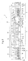
- Fig. 2 shows a turbocompressor 1, which is in a hermetic sealed pressure housing 6 is arranged, each one Pressure housing 6 penetrating supply line 6c and discharge line 6d provided is fluid-conducting to the radial turbocompressor 3 with an outside of the To connect pressure housing 6 arranged device.
- the electric motor 2 comprises the rotor 2b and the stator 2c, the rotor 2b being part of the Motor shaft 2a is, and the motor shaft 2a on both sides in the electromagnetic Radial bearing 5, each comprising a support device 5a and one electromagnetic coil 5b, is mounted in the radial direction.
- the Motor shaft 2a has an axial bearing 7 against radial centrifugal compressor 3 on, which forms part of the motor shaft 2a disc 2d and includes electromagnetic coils 7a.
- the motor shaft 2a is on the other End section via a clutch 4 with the rotor 3a of the Radial turbocompressor 3 connected, the opposite End portion of the rotor 3a is mounted in a radial bearing 5.
- the Motor shaft 2a and rotor 3a form a common shaft 13.
- two compressor wheels 3b are arranged, which has a first compression stage 3c and a second compression stage Train 3d.
- the guide vanes 3f of the are not shown Radial turbo compressor 3.
- the main mass flow 8 of the to be compressed Fluid passes through the inlet opening 6a and the feed line 6c into the first compression stage 3c subsequently to the second compression stage 3d and subsequently via the Discharge 6d directed to the outlet opening 6b.
- a small fraction of the The main mass flow 8 is at the exit point of the first Compression stage 3c derived via a connecting line 11 and as Cooling gas mass flow 9 fed to a filter device 10, which the Cooling gas mass flow 9 cleans of impurities, and the cleaned Cooling gas mass flow 9 as a coolant to the electromagnetic radial bearings 5 and the electric motor 2 feeds.
- the cooling gas mass flow 9 flows in the longitudinal direction of the housing, the radial bearing 5 and subsequently the electric motor 2 and the other Radial bearing 5 supplied, the cooling gas preferably between the Wave 2a and the respective magnet 5b, 2c is performed.
- the Cooling gas mass flow 9 opens to the suction side of the first Compression level 3c, which is in turn compressed by this, and is called Main mass flow 8 and / or further promoted as a cooling gas mass flow 9.
- the connecting line 11 and the filter device 10 can be inside or be arranged outside the pressure housing 6 extending.
- the Turbo compressor 1 according to the embodiment shown in FIG. 2 has the advantage that no seal of the motor shaft 2a or Runner 3a versus atmosphere is required. In addition, there is no seal between between the engine 2 and the first compression stage 3c required.
- the electric motor 2 is to be designed in such a way that it also has Suction pressure or can be operated with standstill pressure.
- the turbocompressor 1 could of course have a plurality in the direction of travel of the rotor 3a have spaced-apart compressor wheels 3b, so for example, a total of four, six, eight or ten compressor wheels 3b.
- the compression pressure to be achieved is largely open upwards, with a corresponding number connected in series Compressor wheels 3b, for example, a compression pressure of 600 bar is achievable.
- the turbocompressor 1 could also have one or more others Radial turbocompressors 3 and / or electric motors 2, which in Direction of the runner 3a; 2a are arranged, with all runs 3a; 2a form a common wave.
- This common wave could go through Radial bearings, in particular magnetic radial bearings 5, can be mounted preferably a single one between each radial turbocompressor 3 Radial bearing 5 is arranged. All radial turbocompressors 3 are preferably third together with the electric motor 2 or the electric motors 2 in one common, single pressure housing 6 arranged.
- the electromagnetic radial bearings 5 and the radial bearings 5 assigned sections of the shafts 2a and 3a have further, for one Components which are obvious to a person skilled in the art and therefore not shown to form an electromagnetic radial bearing 5, such as electrical Coils, ferromagnetic parts etc.
- Fig. 3 shows a longitudinal section of a further embodiment of a Turbocompressor 1 comprising two radial turbocompressors 3, each on Side of the electric motor 2 each arranged a radial turbocompressor 3 and whose rotor 3a is connected to the motor shaft 2a via a coupling 4. Only the upper half of the turbocompressor 1 is shown. It will only be the essential compared to the embodiment of FIG. 2 Differences described in detail.
- the entire wave encompassing the Motor shaft 2a and the two rotor 3a is by four, in the longitudinal direction electromagnetic radial bearings 5 distributed over the entire shaft stored.
- the radial turbocompressor 3 arranged on the left is as Low pressure part connected and has six compressor wheels 3b.
- the radial turbocompressor 3 arranged on the right is a high-pressure part connected and has five compressor wheels 3b. Also shown are the guide vanes 3f.
- the main mass flow 8 occurs via the feed line 6c into the low-pressure part, and after compressing it via a Connection line 12 fed to the high pressure part, the Main mass flow 8 the high pressure part after compression via the Lead 6d leaves.
- a small part of the main mass flow 8 is after the first compression stage 3c as cooling gas mass flow 9 in the Connection line 11 passed, this cooling gas mass flow 9 after the flow through the filter 10 on the right side of the electric motor 2 arranged interior 9c is fed, and then in the longitudinal direction of the motor shaft 2a flowing over the interior 9b of the suction opening flows to the first compression stage 3c.
- part of the Radial turbocompressor 3 located process gas for cooling the Electric motor 2 derived and used.
- the electric motor 2 is in turn designed to to be operable at a suction pressure or a standstill pressure.
- the Connecting line 12 and / or the connecting line 11 as well Filter device 10 could also be entirely within the housing 6 be arranged progressively.
- the radial turbocompressors 3 can for example also in a “back to back “arrangement, in other words such that the forces caused by the two radial turbocompressors 3 on the shaft in act in the opposite direction, so that in the direction of the Motor shaft 2a to compensate and reduce acting thrust forces.
- the housing 6 settles in the embodiments according to FIGS. 3 and 4 from the three sub-housings 6e, 6f, 6g together, the sub-housings 6e, Form 6g part of the radial turbocompressor 3 and the partial housing 6f part of the Motors 2 forms.
- the sub-housings 6e, 6f, 6g are mutually adapted in this way configured that they, as shown in Figures 3 and 4, fixed can be connected to one another, for example by means of screws.
- connection points can also be such mutually adapted to be arranged that are arranged adjacent Part housing when pushing together and connecting with respect to Center the longitudinal axis of the turbocompressor 1 automatically.
- the two partial housings 6e, 6g each have an opening 23a in the outer wall on, which can be closed gas-tight with a cover 23b.
- 3 is the in the partial housing 6g arranged opening 23a shown with cover 23b.
- the Turbocompressor 1 is preferably prefabricated such that the Radial turbocompressor 3 is installed in the respective partial housing 6e, 6g and the electric motor 2 is installed in the sub-housing 6f.
- the so Pre-configured sub-housings 6e, 6f, 6g are assembled Condition transported to the application site.
- the assembly of the Turbocompressor 1 is as follows: After the partial housing 6e, 6f, 6g over the Flanges 6k, 6l are firmly connected, the shaft 3a and the rotor 2b on the one accessible from the outside through the opening 23a Coupling 4 firmly connected. Then the opening 23a with the lid 23b closed tightly and gas-tight.
- the on the clutch 4 Fasteners used, such as screws, are in themselves known and therefore not shown in detail.
- the turbocompressor 1 shown in FIG. 4 essentially has otherwise configured in the housing part 6e the same as the turbocompressor according to FIG. 3 an outlet opening 6h connected to the interior 9b in a fluid-conducting manner, and an adjoining lead 6i through which the Cooling gas mass flow 9 and a small proportion of the Main mass flow 9a emerges and, for example, a plant foreign Process source is fed.
- This arrangement points towards the 3 has the advantage that the pressure in the Derivation 6i subsequent device regardless of the pressure in Radial turbocompressor 3, which pressure is preferably chosen in this way is that the engine cooling takes place at a lower pressure level than in the Embodiment according to FIG.
- the Derivation 6i can be fed to a compressor 24, for example, which compresses the mass flow 9, 9a again the inlet opening 6a feeds.
- the suction pressure generated by the compressor in the discharge line 6i can for example lower than 50 bar.
- a control device 17 which at least to control the electromagnetic radial bearings 5 and the motor 2 serves.
- the sensors 16a, 16b, 16c, 16d arranged, which the position of the entire shaft 13 or the partial shafts 2a, 3a with respect to the radial bearings 5, the sensors 16a, 16b, 16c, 16d via electrical lines 16e, 16f, 16g, 16h with the control device 17 are connected.
- electrical lines 15a, 15b, 15c, 15d which are connected to the control device 17.
- one electrical line 15e is provided, which the control device 17 a power electronics, not shown, with the winding of the Electric motor 2 connects.
- Fig. 5 shows a longitudinal section through a housing 6, the Junction of two sub-housings 6e, 6f is shown.
- the flange 6k of the first partial housing 6e has a recess designed in this way, that the flange 6l of the second sub-housing 6f is accommodated therein, the mutual position of the two sub-housings 6e, 6f at Joining by the flanges 6k, 6l are mutually centered.
- the Flanges 6k, 6l are distributed in the circumferential direction by several arranged screws 6m held together with nut 6n, on the Front of the flanges 6k, 6l a groove running in the circumferential direction is provided, in which a sealing element 6o is arranged, around which the two sub-housings 6e, 6f limited interior to the outside to seal.
- FIG. 6 shows a longitudinal section of a schematically represented housing 6 consisting of three sub-housings 6e, 6f, 6g with flanges 6k, 6l and one Lead 6c and a lead 6d.
- the housing 6 is over two Support elements 18a, 18b are supported on a base 14.
- Within the A base element 6p is arranged in the housing, which has a rigid, in Support extending in the longitudinal direction of the housing 6, in particular a support Forms support surface on which the electromagnetic radial bearing 5th are arranged.
- the function of the basic element 6p is one if possible stable and preferably temperature-insensitive reference plane form on which at least some radial bearings 5 are arranged.
- the Base element 6p can be designed in a variety of embodiments be, for example as a solid, solid plate, as a support or as Grating. On the base element 6p, other components such as the Electric motor 2 or the radial turbocompressor 3 can be anchored.
- the Using a base element 6p enables the electromagnetic Radial bearings 5 mutually very precise and in particular exactly aligned to arrange.
- the common arrangement of the radial bearing 5 on the Base element 6p has the advantage that the attacking Tensile, compressive or shear forces or due to temperature influences mutual displacements of the radial bearings are very small. In addition this arrangement can be set up ready for operation very quickly.
- the bearing force that can be generated by electromagnetic radial bearings is much lower than that of known hydrodynamic bearings Generatable bearing force. That is why the exact mutual Alignment of the electromagnetic radial bearings as well as preventing one mutual displacement of the radial bearings of central importance.
- the Electromagnetic radial bearings are usually operated in such a way that the Shaft is held in the geometric center of the radial bearing. On mutual displacement of the radial bearings has the consequence that the Radial bearing has to exert considerable forces to keep the shaft in the keep geometric center. Because the electromagnetic radial bearing is relative soon reaches a state of magnetic saturation, that has Radial bearings in this situation have less, to support the shaft Available forces.
- the two central radial bearings 5 have a relatively low one mutual distance, so that when there is a mutual offset this two central radial bearings 5 the problem may arise that this in radial forces produce opposing forces, which causes that the residual force of the electromagnetic radial bearing is less or not at all Available.
- Fig. 7 shows a turbocompressor 1 with a compared to 4 separately cooled electric motor 2 between the pressure part of the radial turbocompressor 3 and the electric motor 2 each a system with a double seal, including one Dry gas seal 19 and subsequently a seal 20, arranged, an outlet 21 between the two seals 19, 20, as a vent (Leak to the atmosphere without gas combustion) or flare (leak to the Atmosphere with gas combustion) designed, which is arranged by the housing wall 6 runs.
- the electric motor 2 has a separate, separated by the seals 19, 20 from the radial turbocompressor 3 Cooling circuit on which a connecting line 11 and a cooler 22nd includes.
- a feed line 9d leads additional Cooling gas to, for example, those flowing off via the discharge line 21 To compensate for cooling gas.
- a cooling gas in particular is not aggressive gas such as nitrogen.
- the cooling circuit of the Electric motor 2 can be designed such that it has a pressure in the Range of atmospheric pressure or slightly above. As in 7, the cooling circuit can be designed such that a Small proportion of the cooling gas mass flow 9 via the seal 20 for Outlet 21 arrives. This ensures that the Cooling gas mass flow 9 is not contaminated by foreign gases. in the 7 also flows a small proportion of the Process gas 8 via the seal 19 to the outlet 21.
- the outlet 21 can a so-called flare or vent can be subordinated to the from the Discharge exhaust gases 21 unburned (Vent) or via a to discharge subsequent combustion (flare), especially to the environment to deliver.
- cooling gas 9 has a low pressure and / or that as a cooling gas inexpensive or easily manageable gas can be used, in particular a gas with no aggressive properties.
- turbocompressor 1 An advantage of the turbocompressor 1 according to the invention can be seen in the fact that that the electric motor 2 and the radial turbocompressor 3 together with the corresponding housing parts 6e, 6f can be preassembled so that the Turbo compressor 1 as a housing 6 or as a unit for Installation site can be transported and set up there.
- Lines 11, 12 and the associated components 22 can in a further embodiment also within the housing 6 be arranged progressively.
Landscapes
- Engineering & Computer Science (AREA)
- Mechanical Engineering (AREA)
- General Engineering & Computer Science (AREA)
- Physics & Mathematics (AREA)
- Thermal Sciences (AREA)
- Electromagnetism (AREA)
- Structures Of Non-Positive Displacement Pumps (AREA)
Abstract
Description
- dass der Zusammenbau des gesamten Turboverdichters sehr einfach ist,
- dass in jedem Teilgehäuse eine rotierbaren Einheit angeordnet ist, welche separat balanciert und ausgewuchtet werden kann,
- dass jedes Teilgehäuse mit der sich darin befindlichen rotierbaren Einheit auch von unterschiedlichen Lieferanten bezogen werden kann. Insbesondere kann der Elektromotor und der Radialturboverdichter von unterschiedlichen Lieferanten bezogen werden.
- dass der Unterhalt des Turboverdichters einfacher und kostengünstiger ist.
- Fig. 1
- eine schematische Anordnung eines bekannten Turboverdichters;
- Fig. 2
- ein Längsschnitt eines Turboverdichters mit einem Elektromotor sowie einem Radialturboverdichter;
- Fig. 3
- ein Längsschnitt eines Turboverdichters mit beidseitig angeordneten Radialturboverdichtern;
- Fig. 4
- ein weiterer Längsschnitt eines Turboverdichters mit beidseitig angeordneten Radialturboverdichtern;
- Fig. 5
- ein Längsschnitt durch die Verbindungsstelle zweier Teilgehäuse;
- Fig. 6
- ein Längsschnitt eines schematisch dargestellten Gehäuses bestehend aus drei Teilgehäusen;
- Fig. 7
- ein Längsschnitt eines Turboverdichters mit separatem Kühlsystem.
Claims (15)
- Turboverdichter (1) umfassend einen Elektromotor (2), einen mehrstufigen Radialturboverdichter (3) sowie eine gemeinsame Welle (13), wobei ein Teilabschnitt der Welle (13) als Rotor (2b) des Elektromotors (2) ausgebildet ist, und wobei ein weiterer Teilabschnitt der Welle (13) als Läufer (3e) des Radialturboverdichters (3) ausgebildet ist, wobei der Läufer (3e) eine Verdichterwelle (3a) sowie damit verbundene Verdichterräder (3b) umfasst, und wobei zum Lagern der Welle (13) mehrere elektromagnetische Radiallager (5) in Verlaufsrichtung der Welle (13) beabstandet angeordnet sind, und wobei zwischen dem Rotor (2b) des Elektromotors (2) und dem Verdichterrad (3b) ein einziges elektromagnetisches Radiallager (5) angeordnet ist, und wobei der Elektromotor (2), der Radialturboverdichter (3), die Welle (13) sowie die Radiallager (5) in einem gemeinsamen, nach aussen gasdichten Gehäuse (6) angeordnet sind, dadurch gekennzeichnet, dass das Gehäuse (6) aus mehreren Teilgehäusen (6e, 6f, 6g) besteht, welche fest miteinander verbindbar sind, dass der Elektromotor (2) in einem Teilgehäuse (6f) und der Radialturboverdichter (3) in einem Teilgehäuse (6e, 6g) angeordnet ist, und dass der Rotor (2b) des Elektromotors (2) sowie der Läufer (3e) des Radialturboverdichters (3) über eine zwischen dem Rotor (2b) des Elektromotors (2) und dem Verdichterrad (3b) angeordnete Kupplung (4) zu einer gemeinsamen Welle (13) verbindbar sind.
- Turboverdichter (1) nach Anspruch 1, dadurch gekennzeichnet, dass zumindest ein Teilgehäuse (6e, 6f, 6g) eine verschliessbare Öffnung (23a) aufweist, welche im Bereich der Kupplung (4) angeordnet ist.
- Turboverdichter (1) nach einem der vorhergehenden Ansprüche, dadurch gekennzeichnet, dass die Kupplung (4) axial im Bereich der Verbindungsstellen (6k, 6l) zweier Teilgehäuse (6e, 6f, 6g) angeordnet ist.
- Turboverdichter (1) nach einem der vorhergehenden Ansprüche, dadurch gekennzeichnet, dass die Radiallager (5) auf einem gemeinsamen Basiselement (6p) abgestützt sind.
- Turboverdichter (1) nach einem der vorhergehenden Ansprüche, dadurch gekennzeichnet, dass das gemeinsame Gehäuse (6), in welchem der Elektromotor (2), der Radialturboverdichter (3), die Welle (13) sowie die Radiallager (5) angeordnet sind, ein Basiselement (6p) umfasst, auf welchem die Radiallager (5) abgestützt sind.
- Turboverdichter (1) nach Anspruch 4 oder 5, dadurch gekennzeichnet, dass ein Teil der Innenseite des Gehäuses (6) das Basiselement (6p) ausbildet.
- Turboverdichter (1) nach einem der vorhergehenden Ansprüche, dadurch gekennzeichnet, dass die Kupplung (4) eine sehr hohe Steifigkeit aufweist, um der Welle (13) in Längsrichtung eine hohe und insbesondere homogene Steifigkeit zu verleihen.
- Turboverdichter (1) nach einem der vorhergehenden Ansprüche, dadurch gekennzeichnet, dass beidseits des Rotors (2b) des Elektromotors (2) ein mehrstufiger Radialturboverdichter (3) mit je einem Läufer (3e) angeordnet ist.
- Turboverdichter (1) nach einem der vorhergehenden Ansprüche, dadurch gekennzeichnet, dass das gemeinsame Gehäuse (6) eine von aussen in den Radialturboverdichter (3) mündende Zuleitung (6c) und Ableitung (6d) aufweist, um ausserhalb des Gehäuses (6) angeordnete Vorrichtungen fluidleitend mit dem Radialturboverdichter (3) zu verbinden.
- Turboverdichter (1) nach einem der vorhergehenden Ansprüche, dadurch gekennzeichnet, dass der Elektromotor (2) als ein Saugdruck resistenter Motor ausgestaltet ist, und dass der Elektromotor (2) an dessen einem, saugseitigen Ende fluidleitend mit dem Einlass einer bestimmten Stufe (3c, 3d) des Radialturboverdichters (3) verbunden ist, und dass das andere Ende des Elektromotors (2) mit dem Auslass der bestimmten Stufe (3c, 3d) oder einer nachfolgenden Stufe des Radialturboverdichters (3) fluidleitend verbunden ist, wobei als bestimmte Stufe (3c, 3d) vorzugsweise die erste Stufe (3c) gewählt ist.
- Turboverdichter (1) nach einem der vorhergehenden Ansprüche, dadurch gekennzeichnet, dass zwischen dem Elektromotor (2) und dem am saugseitigen Ende des Elektromotors (2) angeordneten Radialturboverdichter (3) kein Dichtungssystem angeordnet ist.
- Turboverdichter (1) nach einem der Ansprüche 1 bis 10, dadurch gekennzeichnet, dass zwischen dem Radialturboverdichter (3) und dem Elektromotor (2) ein Dichtungssystem (19,20) angeordnet ist, und dass der Elektromotor (2) einen separaten Kühlkreislauf (22,11) aufweist.
- Turboverdichter (1) nach einem der vorhergehenden Ansprüche, dadurch gekennzeichnet, dass ein auf die Welle (13) wirkendes Axiallager (7) in Längsrichtung der Welle (13) insbesondere zwischen dem Elektromotor (2) und dem Radialturboverdichter (3) angeordnet ist.
- Turboverdichter (1) nach einem der vorhergehenden Ansprüche, dadurch gekennzeichnet, dass entlang der Welle (13) Sensoren (16a, 16b, 16c) zum Erfassen der Lage der Welle (13) angeordnet sind, und dass eine Steuer- und Regelvorrichtung (17) vorgesehen ist, welche mit den Sensoren (16a, 16b, 16c) Signal leitend verbunden ist, und dass die elektromagnetischen Radiallager (5) elektromagnetische Spulen (5b) aufweisen, welche mit der Steuer- und Regelvorrichtung (17) Signal leitend verbunden sind.
- Anlage umfassend einen Turboverdichter nach einem der vorhergehenden Ansprüche.
Priority Applications (7)
| Application Number | Priority Date | Filing Date | Title |
|---|---|---|---|
| EP00810274A EP1074746B1 (de) | 1999-07-16 | 2000-03-31 | Turboverdichter |
| CA002312081A CA2312081C (en) | 1999-07-16 | 2000-06-20 | Cooling system for electromagnetic bearings of a turbocompressor |
| US09/597,938 US6464469B1 (en) | 1999-07-16 | 2000-06-20 | Cooling system for electromagnetic bearings of a turbocompressor |
| DE20011219U DE20011219U1 (de) | 1999-07-16 | 2000-06-26 | Turboverdichter |
| JP2000192339A JP4460116B2 (ja) | 1999-07-16 | 2000-06-27 | ターボ圧縮機 |
| KR1020000039922A KR100779959B1 (ko) | 1999-07-16 | 2000-07-12 | 터보압축기 |
| CNB001201131A CN1153907C (zh) | 1999-07-16 | 2000-07-17 | 涡轮压缩机装置 |
Applications Claiming Priority (3)
| Application Number | Priority Date | Filing Date | Title |
|---|---|---|---|
| EP99810640 | 1999-07-16 | ||
| EP99810640A EP0990798A1 (de) | 1999-07-16 | 1999-07-16 | Turboverdichter |
| EP00810274A EP1074746B1 (de) | 1999-07-16 | 2000-03-31 | Turboverdichter |
Publications (3)
| Publication Number | Publication Date |
|---|---|
| EP1074746A2 true EP1074746A2 (de) | 2001-02-07 |
| EP1074746A3 EP1074746A3 (de) | 2002-05-15 |
| EP1074746B1 EP1074746B1 (de) | 2005-05-18 |
Family
ID=26073836
Family Applications (1)
| Application Number | Title | Priority Date | Filing Date |
|---|---|---|---|
| EP00810274A Revoked EP1074746B1 (de) | 1999-07-16 | 2000-03-31 | Turboverdichter |
Country Status (7)
| Country | Link |
|---|---|
| US (1) | US6464469B1 (de) |
| EP (1) | EP1074746B1 (de) |
| JP (1) | JP4460116B2 (de) |
| KR (1) | KR100779959B1 (de) |
| CN (1) | CN1153907C (de) |
| CA (1) | CA2312081C (de) |
| DE (1) | DE20011219U1 (de) |
Cited By (7)
| Publication number | Priority date | Publication date | Assignee | Title |
|---|---|---|---|---|
| NL1018212C2 (nl) | 2001-06-05 | 2002-12-10 | Siemens Demag Delaval Turbomac | Compressoreenheid omvattende een centrifugaalcompressor en een elektromotor. |
| NL1021656C2 (nl) | 2002-10-15 | 2004-04-16 | Siemens Demag Delaval Turbomac | Compressoreenheid met gemeenschappelijke behuizing voor elektromotor en compressor, werkwijze voor het vervaardigen van een scheidingswand voor een compressoreenheid en gebruik van een compressoreenheid. |
| WO2013160274A1 (de) * | 2012-04-27 | 2013-10-31 | Siemens Aktiengesellschaft | Strömungsmaschine sowie verfahren zur kühlen einer solchen |
| RU2670993C1 (ru) * | 2017-08-02 | 2018-10-29 | Василий Сигизмундович Марцинковский | Компрессорный агрегат компримирования азото-водородной смеси в производстве аммиака (варианты) |
| EP3726081A1 (de) | 2019-04-16 | 2020-10-21 | GE Energy Power Conversion Technology Ltd. | Mechanisches system und angekoppelter motorkompressor |
| US11274679B2 (en) | 2017-02-14 | 2022-03-15 | Danfoss A/S | Oil free centrifugal compressor for use in low capacity applications |
| US12006951B2 (en) | 2021-07-14 | 2024-06-11 | Man Energy Solutions Se | Turbo-machine arrangement |
Families Citing this family (93)
| Publication number | Priority date | Publication date | Assignee | Title |
|---|---|---|---|---|
| AU2003233369A1 (en) * | 2003-03-10 | 2004-10-11 | Thermodyn | Integrated centrifugal compressor unit |
| RU2333398C2 (ru) * | 2003-03-10 | 2008-09-10 | Термодин | Центробежный компрессорный агрегат |
| RU2304233C2 (ru) * | 2003-04-11 | 2007-08-10 | Термодин | Центробежный компрессорный агрегат |
| NO323324B1 (no) * | 2003-07-02 | 2007-03-19 | Kvaerner Oilfield Prod As | Fremgangsmate for regulering at trykket i en undervannskompressormodul |
| ATE348267T1 (de) * | 2003-07-05 | 2007-01-15 | Man Turbo Ag Schweiz | Kompressorvorrichtung und verfahren zum betrieb derselben |
| EP1482179B1 (de) * | 2003-07-05 | 2006-12-13 | MAN TURBO AG Schweiz | Kompressorvorrichtung und Verfahren zum Betrieb derselben |
| DE102004023148A1 (de) * | 2004-05-07 | 2005-11-24 | Atlas Copco Energas Gmbh | Turbomaschine für Tieftemperaturanwendungen |
| DE102004027594B4 (de) * | 2004-06-05 | 2006-06-29 | Man B & W Diesel Ag | Strömungsmaschine mit radial durchströmtem Verdichterrad |
| US8075668B2 (en) | 2005-03-29 | 2011-12-13 | Dresser-Rand Company | Drainage system for compressor separators |
| DE102005039033B3 (de) * | 2005-08-18 | 2006-11-02 | Atlas Copco Energas Gmbh | Turbomaschine für Tieftemperaturanwendungen |
| DE102005052077B4 (de) * | 2005-10-28 | 2016-11-24 | Man Diesel & Turbo Se | Vorrichtung zur seitlichen Montage und Demontage eines Kompressorbarrels |
| FR2896101B1 (fr) * | 2006-01-10 | 2008-04-18 | Mecanique Magnetique Sa Soc D | Dispositif de filtrage de particules dans une machine tournante a paliers magnetiques actifs |
| ITMI20060294A1 (it) * | 2006-02-17 | 2007-08-18 | Nuovo Pignone Spa | Motocompressore |
| JP2009530537A (ja) * | 2006-03-24 | 2009-08-27 | シーメンス アクチエンゲゼルシヤフト | 圧縮機装置 |
| NO326735B1 (no) * | 2006-06-30 | 2009-02-09 | Aker Subsea As | Fremgangsmåte og anordning for beskyttelse av kompressormoduler mot uønsket innstrømming av forurenset gass. |
| BRPI0716867A2 (pt) | 2006-09-19 | 2013-10-15 | Dresser Rand Co | Vedação de tambor de separador rotativo |
| BRPI0718513B1 (pt) | 2006-09-21 | 2018-10-23 | Dresser Rand Co | conjunto de manuseio de fluido para uma máquina para fluidos |
| BRPI0717571B1 (pt) | 2006-09-25 | 2018-11-27 | Dresser Rand Co | carretel de conexão para conectar um invólucro do compressor com um invólucro do acionador de um sistema de compressão industrial |
| US8231336B2 (en) | 2006-09-25 | 2012-07-31 | Dresser-Rand Company | Fluid deflector for fluid separator devices |
| BRPI0717087B1 (pt) | 2006-09-25 | 2018-10-16 | Dresser Rand Co | sistema de carretel conector para conectar um primeiro componente e um segundo componente de um sistema de compressão industrial |
| US8733726B2 (en) | 2006-09-25 | 2014-05-27 | Dresser-Rand Company | Compressor mounting system |
| EP2066988A4 (de) | 2006-09-25 | 2012-01-04 | Dresser Rand Co | Kopplungsüberwachungssystem |
| EP2415507A1 (de) | 2006-09-26 | 2012-02-08 | Dresser-Rand Company | Verbesserte statische Flüssigkeitstrennungsvorrichtung |
| US8156757B2 (en) * | 2006-10-06 | 2012-04-17 | Aff-Mcquay Inc. | High capacity chiller compressor |
| US7700207B2 (en) * | 2006-11-09 | 2010-04-20 | Gm Global Technology Operations, Inc. | Turbocompressor shutdown mechanism |
| US20080199326A1 (en) * | 2007-02-21 | 2008-08-21 | Honeywell International Inc. | Two-stage vapor cycle compressor |
| US7901177B2 (en) * | 2007-03-01 | 2011-03-08 | Siemens Energy, Inc. | Fluid pump having multiple outlets for exhausting fluids having different fluid flow characteristics |
| US8047809B2 (en) * | 2007-04-30 | 2011-11-01 | General Electric Company | Modular air compression apparatus with separate platform arrangement |
| DE102007032933B4 (de) * | 2007-07-14 | 2015-02-19 | Atlas Copco Energas Gmbh | Turbomaschine |
| BRPI0908051A2 (pt) | 2008-03-05 | 2015-08-11 | Dresser Rand Co | Conjunto compressor que inclui separador e bomba ejetora |
| CN102016326B (zh) * | 2008-03-13 | 2013-09-11 | Aaf-麦克维尔公司 | 大容量制冷机压缩机 |
| EP2113671A1 (de) * | 2008-04-28 | 2009-11-04 | Siemens Aktiengesellschaft | Anordnung mit einem elektrischen Motor und einer Pumpe |
| DE102008031994B4 (de) * | 2008-04-29 | 2011-07-07 | Siemens Aktiengesellschaft, 80333 | Fluidenergiemaschine |
| US7922218B2 (en) | 2008-06-25 | 2011-04-12 | Dresser-Rand Company | Shear ring casing coupler device |
| US8079805B2 (en) | 2008-06-25 | 2011-12-20 | Dresser-Rand Company | Rotary separator and shaft coupler for compressors |
| US8062400B2 (en) | 2008-06-25 | 2011-11-22 | Dresser-Rand Company | Dual body drum for rotary separators |
| DE102008038787A1 (de) | 2008-08-13 | 2010-02-18 | Siemens Aktiengesellschaft | Fluidenergiemaschine |
| DE102009004376B4 (de) * | 2009-01-12 | 2016-06-16 | Man Diesel & Turbo Se | Verfahren und System zur Steuerung eines Turbokompressorverbundes |
| US8210804B2 (en) | 2009-03-20 | 2012-07-03 | Dresser-Rand Company | Slidable cover for casing access port |
| US8087901B2 (en) | 2009-03-20 | 2012-01-03 | Dresser-Rand Company | Fluid channeling device for back-to-back compressors |
| US8061972B2 (en) | 2009-03-24 | 2011-11-22 | Dresser-Rand Company | High pressure casing access cover |
| IT1399171B1 (it) | 2009-07-10 | 2013-04-11 | Nuovo Pignone Spa | Unita' di compressione ad alta pressione per fluidi di processo di impianti industriali e relativo metodo di funzionamento |
| EP2290241A1 (de) | 2009-07-13 | 2011-03-02 | Siemens Aktiengesellschaft | Turbokompressoreinheit mit einem Kühlsystem |
| BE1019030A5 (nl) | 2009-08-03 | 2012-01-10 | Atlas Copco Airpower Nv | Turbocompressorsysteem. |
| US8414692B2 (en) | 2009-09-15 | 2013-04-09 | Dresser-Rand Company | Density-based compact separator |
| IT1395822B1 (it) * | 2009-10-12 | 2012-10-26 | Nuovo Pignone Spa | Metodo e macchinario con combinazione di dispositivi di separazione particelle e di regolazione flusso |
| US9095856B2 (en) | 2010-02-10 | 2015-08-04 | Dresser-Rand Company | Separator fluid collector and method |
| IT1399881B1 (it) * | 2010-05-11 | 2013-05-09 | Nuova Pignone S R L | Configurazione di tamburo di bilanciamento per rotori di compressore |
| US8673159B2 (en) | 2010-07-15 | 2014-03-18 | Dresser-Rand Company | Enhanced in-line rotary separator |
| US8663483B2 (en) | 2010-07-15 | 2014-03-04 | Dresser-Rand Company | Radial vane pack for rotary separators |
| US8657935B2 (en) | 2010-07-20 | 2014-02-25 | Dresser-Rand Company | Combination of expansion and cooling to enhance separation |
| WO2012012143A2 (en) | 2010-07-21 | 2012-01-26 | Dresser-Rand Company | Multiple modular in-line rotary separator bundle |
| EP2614216B1 (de) | 2010-09-09 | 2017-11-15 | Dresser-Rand Company | Spülungsaktivierter gesteuerter strömungsabfluss |
| US9726196B2 (en) * | 2010-10-27 | 2017-08-08 | Dresser-Rand Company | System and cooling for rapid pressurization of a motor-bearing cooling loop for a hermetically sealed motor/compressor system |
| FR2969722B1 (fr) | 2010-12-22 | 2013-01-04 | Thermodyn | Groupe motocompresseur a accouplement torsible place dans un arbre creux du compresseur |
| RU2448277C1 (ru) * | 2010-12-28 | 2012-04-20 | Закрытое акционерное общество "Научно-исследовательский и конструкторский институт центробежных и роторных компрессоров им. В.Б. Шнеппа" | Способ разгрузки и защиты упорного подшипника двухсекционного центробежного компрессора |
| US8994237B2 (en) | 2010-12-30 | 2015-03-31 | Dresser-Rand Company | Method for on-line detection of liquid and potential for the occurrence of resistance to ground faults in active magnetic bearing systems |
| EP2659277B8 (de) | 2010-12-30 | 2018-05-23 | Dresser-Rand Company | Verfahren zur online-erkennung von bodenwiderstandsfehlern in aktiven magnetlagersystemen |
| JP5697243B2 (ja) * | 2011-02-25 | 2015-04-08 | 三菱重工コンプレッサ株式会社 | 回転軸組立体およびこれを備えた遠心圧縮機 |
| RU2458253C1 (ru) * | 2011-03-18 | 2012-08-10 | Закрытое акционерное общество "Научно-исследовательский и конструкторский институт центробежных и роторных компрессоров им. В.Б. Шнеппа" | Центробежный компрессорный агрегат |
| US9551349B2 (en) | 2011-04-08 | 2017-01-24 | Dresser-Rand Company | Circulating dielectric oil cooling system for canned bearings and canned electronics |
| CN102200136B (zh) * | 2011-05-25 | 2012-09-05 | 北京虎渡能源科技有限公司 | 一种空气悬浮供气可调高速电机直驱鼓风机 |
| EP2715167B1 (de) | 2011-05-27 | 2017-08-30 | Dresser-Rand Company | Segmentiertes auslauflager für magnetlagersysteme |
| US8851756B2 (en) | 2011-06-29 | 2014-10-07 | Dresser-Rand Company | Whirl inhibiting coast-down bearing for magnetic bearing systems |
| DE102012016844A1 (de) * | 2011-08-30 | 2013-02-28 | Ksb Aktiengesellschaft | Turbokompressor und Verwendung |
| FR2980538B1 (fr) | 2011-09-27 | 2013-10-25 | Thermodyn | Groupe moto-compresseur a cartouche amovible |
| DE102012204403A1 (de) * | 2012-03-20 | 2013-09-26 | Man Diesel & Turbo Se | Radialverdichtereinheit |
| US9371835B2 (en) | 2013-07-19 | 2016-06-21 | Praxair Technology, Inc. | Coupling for directly driven compressor |
| FR2997739B1 (fr) * | 2012-11-07 | 2015-01-09 | Thermodyn | Compresseur comprenant un equilibrage de poussee |
| EP2853749A1 (de) * | 2013-09-25 | 2015-04-01 | Siemens Aktiengesellschaft | Strömungsenergiemaschine, Betriebsverfahren |
| ITCO20130069A1 (it) * | 2013-12-18 | 2015-06-19 | Nuovo Pignone Srl | Compressore centrifugo multistadio |
| DE102014009146A1 (de) * | 2014-06-20 | 2015-12-24 | Ziehl-Abegg Se | Elektromotor mit einem Rotor, einem Stator und einem Elektronikgehäuse sowie Lüfterrad für einen Elektromotor |
| JP6117423B2 (ja) * | 2014-11-17 | 2017-04-19 | 株式会社日立製作所 | 圧縮装置 |
| US11421696B2 (en) | 2014-12-31 | 2022-08-23 | Ingersoll-Rand Industrial U.S., Inc. | Multi-stage compressor with single electric direct drive motor |
| EP3121449B1 (de) * | 2015-07-22 | 2022-10-05 | Thermodyn | Unterwasserradialverdichter mit horizontaler welle und mit lediglich einem axialschublager |
| DE102015214788B4 (de) | 2015-08-03 | 2025-01-02 | Hanon Systems Efp Deutschland Gmbh | Elektrischer Verdichter zum Verdichten eines Gases, insbesondere für ein Kraftfahrzeug |
| IT201600120314A1 (it) | 2016-11-28 | 2018-05-28 | Nuovo Pignone Tecnologie Srl | Turbo-compressore e metodo di funzionamento di un turbo-compressore |
| BE1024644B1 (nl) * | 2017-03-07 | 2018-05-14 | Atlas Copco Airpower Naamloze Vennootschap | Compressormodule voor het comprimeren van gas en compressor daarmee uitgerust |
| GB201708289D0 (en) * | 2017-05-24 | 2017-07-05 | Rolls Royce Plc | Preventing electrical breakdown |
| IT201700097796A1 (it) * | 2017-08-31 | 2019-03-03 | Nuovo Pignone Tecnologie Srl | Sistemi di turbomacchine con refrigerazione di cuscini magnetici attivi e metodo |
| FR3072428B1 (fr) | 2017-10-16 | 2019-10-11 | L'air Liquide Societe Anonyme Pour L'etude Et L'exploitation Des Procedes Georges Claude | Dispositif et procede de compression et machine de refrigeration |
| FR3072429B1 (fr) * | 2017-10-16 | 2020-06-19 | L'air Liquide Societe Anonyme Pour L'etude Et L'exploitation Des Procedes Georges Claude | Dispositif et procede de compression |
| FR3088386B1 (fr) * | 2018-11-13 | 2021-01-08 | Thermodyn | Dispositif de filtration pour un groupe moto-compresseur |
| IT201900003077A1 (it) * | 2019-03-04 | 2020-09-04 | Nuovo Pignone Tecnologie Srl | Configurazione di turbomacchina compressore-espantore multistadio |
| KR102734827B1 (ko) * | 2019-04-08 | 2024-11-28 | 엘지전자 주식회사 | 터보 냉동기 |
| JP7429541B2 (ja) * | 2020-01-06 | 2024-02-08 | 三菱重工コンプレッサ株式会社 | 圧縮機システム |
| US11821435B2 (en) | 2020-07-02 | 2023-11-21 | Siemens Energy Global GmbH & Co. KG | Compressor rotor having flow loop through tie bolt |
| US20220010734A1 (en) * | 2020-07-08 | 2022-01-13 | Ge Energy Power Conversion Technology Limited | Mechanical drive system and associated motor compressor |
| CN114562480B (zh) * | 2022-03-24 | 2025-04-29 | 哈尔滨汽轮机厂有限责任公司 | 一种适应600℃排气温度的多级离心压缩机转子结构 |
| CN115388017B (zh) * | 2022-09-26 | 2023-09-19 | 烟台东德实业有限公司 | 一种高速离心空压机的膨胀端总成 |
| DE102023136182A1 (de) * | 2023-12-21 | 2025-06-26 | Man Energy Solutions Se | Strömungsmaschinenanordnung, Verwendung derselben und Verfahren zur Verflüssigung von Wasserstoff |
| DE102025103417B3 (de) | 2025-01-30 | 2026-06-25 | Everllence Se | Strömungsmaschinenanordnung |
| CN119900721A (zh) * | 2025-04-02 | 2025-04-29 | 东方电气集团东方电机有限公司 | 一种成撬设计的氦气压缩机 |
Citations (1)
| Publication number | Priority date | Publication date | Assignee | Title |
|---|---|---|---|---|
| DE3729486C1 (de) | 1987-09-03 | 1988-12-15 | Gutehoffnungshuette Man | Kompressoreinheit |
Family Cites Families (11)
| Publication number | Priority date | Publication date | Assignee | Title |
|---|---|---|---|---|
| CH663644A5 (de) * | 1982-02-22 | 1987-12-31 | Bbc Brown Boveri & Cie | Turboverdichter. |
| FR2528127A1 (fr) * | 1982-06-04 | 1983-12-09 | Creusot Loire | Moto-compresseur centrifuge electrique integre a grande vitesse |
| EP0297691A1 (de) * | 1987-06-11 | 1989-01-04 | Acec Energie S.A. | Motor- Kompressor-Aggregat |
| GB9404436D0 (en) * | 1994-03-08 | 1994-04-20 | Welsh Innovations Ltd | Compressor |
| IL109967A (en) * | 1993-06-15 | 1997-07-13 | Multistack Int Ltd | Compressor |
| US5698917A (en) * | 1995-09-25 | 1997-12-16 | Glacier Rpb Inc. | Electromagnetic bearing with a stationary armature canning arrangement |
| JPH09132924A (ja) * | 1995-11-08 | 1997-05-20 | Shin Caterpillar Mitsubishi Ltd | 建設機械の点検用カバーおよびこれを備えた建設機械 |
| JP3425308B2 (ja) * | 1996-09-17 | 2003-07-14 | 株式会社 日立インダストリイズ | 多段圧縮機 |
| JP3399800B2 (ja) * | 1997-09-24 | 2003-04-21 | イビデン株式会社 | モータ及びターボ分子ポンプ |
| KR100273380B1 (ko) * | 1997-12-26 | 2001-01-15 | 구자홍 | 터보 압축기 |
| JP3425351B2 (ja) * | 1998-01-13 | 2003-07-14 | 株式会社 日立インダストリイズ | 2段遠心圧縮機 |
-
2000
- 2000-03-31 EP EP00810274A patent/EP1074746B1/de not_active Revoked
- 2000-06-20 US US09/597,938 patent/US6464469B1/en not_active Expired - Lifetime
- 2000-06-20 CA CA002312081A patent/CA2312081C/en not_active Expired - Lifetime
- 2000-06-26 DE DE20011219U patent/DE20011219U1/de not_active Expired - Lifetime
- 2000-06-27 JP JP2000192339A patent/JP4460116B2/ja not_active Expired - Lifetime
- 2000-07-12 KR KR1020000039922A patent/KR100779959B1/ko not_active Expired - Lifetime
- 2000-07-17 CN CNB001201131A patent/CN1153907C/zh not_active Expired - Lifetime
Patent Citations (1)
| Publication number | Priority date | Publication date | Assignee | Title |
|---|---|---|---|---|
| DE3729486C1 (de) | 1987-09-03 | 1988-12-15 | Gutehoffnungshuette Man | Kompressoreinheit |
Cited By (10)
| Publication number | Priority date | Publication date | Assignee | Title |
|---|---|---|---|---|
| NL1018212C2 (nl) | 2001-06-05 | 2002-12-10 | Siemens Demag Delaval Turbomac | Compressoreenheid omvattende een centrifugaalcompressor en een elektromotor. |
| WO2002099286A1 (en) | 2001-06-05 | 2002-12-12 | Siemens Demag Delaval Turbomachinery B.V. | Compressor unit comprising a centrifugal compressor and an electric motor |
| US7156627B2 (en) | 2001-06-05 | 2007-01-02 | Siemens Industrial Turbomachinery B.V. | Compressor unit comprising a centrifugal compressor and an electric motor |
| EP1942280A3 (de) * | 2001-06-05 | 2017-04-19 | Siemens Aktiengesellschaft | Kompressoreinheit mit einem Zentrifugalkompressor und einem Elektromotor |
| NL1021656C2 (nl) | 2002-10-15 | 2004-04-16 | Siemens Demag Delaval Turbomac | Compressoreenheid met gemeenschappelijke behuizing voor elektromotor en compressor, werkwijze voor het vervaardigen van een scheidingswand voor een compressoreenheid en gebruik van een compressoreenheid. |
| WO2013160274A1 (de) * | 2012-04-27 | 2013-10-31 | Siemens Aktiengesellschaft | Strömungsmaschine sowie verfahren zur kühlen einer solchen |
| US11274679B2 (en) | 2017-02-14 | 2022-03-15 | Danfoss A/S | Oil free centrifugal compressor for use in low capacity applications |
| RU2670993C1 (ru) * | 2017-08-02 | 2018-10-29 | Василий Сигизмундович Марцинковский | Компрессорный агрегат компримирования азото-водородной смеси в производстве аммиака (варианты) |
| EP3726081A1 (de) | 2019-04-16 | 2020-10-21 | GE Energy Power Conversion Technology Ltd. | Mechanisches system und angekoppelter motorkompressor |
| US12006951B2 (en) | 2021-07-14 | 2024-06-11 | Man Energy Solutions Se | Turbo-machine arrangement |
Also Published As
| Publication number | Publication date |
|---|---|
| EP1074746A3 (de) | 2002-05-15 |
| JP2001041191A (ja) | 2001-02-13 |
| US6464469B1 (en) | 2002-10-15 |
| KR20010015305A (ko) | 2001-02-26 |
| KR100779959B1 (ko) | 2007-11-28 |
| CN1153907C (zh) | 2004-06-16 |
| CA2312081C (en) | 2004-03-02 |
| CA2312081A1 (en) | 2001-01-16 |
| JP4460116B2 (ja) | 2010-05-12 |
| EP1074746B1 (de) | 2005-05-18 |
| CN1281101A (zh) | 2001-01-24 |
| DE20011219U1 (de) | 2000-10-05 |
Similar Documents
| Publication | Publication Date | Title |
|---|---|---|
| EP1074746B1 (de) | Turboverdichter | |
| EP1069313A2 (de) | Turboverdichter | |
| DE3729486C1 (de) | Kompressoreinheit | |
| EP1993893B1 (de) | Kompressoranordnung | |
| EP2017435A2 (de) | Turbomaschine mit elektrischer Maschine und Magnetlagern | |
| DE3600124A1 (de) | Geblaese zum umwaelzen grosser gasmengen, insbesondere fuer hochleistungs-laser | |
| EP2122169A1 (de) | Fluidarbeitsmaschine | |
| DE69614490T2 (de) | Gebläse für gaslaser | |
| EP0408791A1 (de) | Reibungspumpe mit glockenförmigem Rotor | |
| DE29904410U1 (de) | Schraubenkompressor | |
| DE10003018B4 (de) | Turboverdichter | |
| EP0990798A1 (de) | Turboverdichter | |
| EP0653566B1 (de) | Getriebeverdichter für die Verdichtung von Sauerstoff | |
| EP0569455B1 (de) | Trockenlaufende zweiwellenvakuumpumpe | |
| EP0750118B1 (de) | Verfahren und Vorrichtung zur Sicherung der Funktionstüchtigkeit von Gasdichtungen bei Turboverdichtern | |
| EP0290664B1 (de) | Zweiwellenpumpe | |
| DE602004001156T2 (de) | Verdichtereinheit mit unterstützter Kühlung | |
| DE102012207019B4 (de) | Strömungsmaschine sowie Verfahren zur Kühlen einer solchen | |
| DE102006060865B4 (de) | Vorrichtung | |
| DE2100690B2 (de) | Einbaublock zum einbau in einen mehrstufigen radialverdichter | |
| DE102021120100A1 (de) | Stirnradgetriebe | |
| EP0942172B1 (de) | Mehrwellenvakuumpumpe | |
| EP0713001B1 (de) | Gas-Expansionsmaschine | |
| EP0814268A1 (de) | Modularer Bausatz zur Herstellung einer Pumpe, insbes. einer Permanentmagnetkupplungspumpe | |
| EP0461131B1 (de) | Axialschubentlastungseinrichtung |
Legal Events
| Date | Code | Title | Description |
|---|---|---|---|
| PUAI | Public reference made under article 153(3) epc to a published international application that has entered the european phase |
Free format text: ORIGINAL CODE: 0009012 |
|
| AK | Designated contracting states |
Kind code of ref document: A2 Designated state(s): AT BE CH CY DE DK ES FI FR GB GR IE IT LI LU MC NL PT SE |
|
| AX | Request for extension of the european patent |
Free format text: AL;LT;LV;MK;RO;SI |
|
| RAP1 | Party data changed (applicant data changed or rights of an application transferred) |
Owner name: MAN TURBOMASCHINEN AG GHH BORSIG |
|
| PUAL | Search report despatched |
Free format text: ORIGINAL CODE: 0009013 |
|
| AK | Designated contracting states |
Kind code of ref document: A3 Designated state(s): AT BE CH CY DE DK ES FI FR GB GR IE IT LI LU MC NL PT SE |
|
| AX | Request for extension of the european patent |
Free format text: AL;LT;LV;MK;RO;SI |
|
| RIC1 | Information provided on ipc code assigned before grant |
Free format text: 7F 04D 25/06 A, 7F 04D 17/12 B, 7F 04D 29/04 B, 7F 04D 29/10 B, 7F 04D 29/58 B |
|
| 17P | Request for examination filed |
Effective date: 20020419 |
|
| RAP1 | Party data changed (applicant data changed or rights of an application transferred) |
Owner name: MAN TURBOMASCHINEN AG |
|
| RAP1 | Party data changed (applicant data changed or rights of an application transferred) |
Owner name: MAN TURBOMASCHINEN AG |
|
| AKX | Designation fees paid |
Designated state(s): AT BE CH CY DE DK ES FI FR GB GR IE IT LI LU MC NL PT SE |
|
| GRAP | Despatch of communication of intention to grant a patent |
Free format text: ORIGINAL CODE: EPIDOSNIGR1 |
|
| RAP1 | Party data changed (applicant data changed or rights of an application transferred) |
Owner name: MAN TURBO AG |
|
| GRAS | Grant fee paid |
Free format text: ORIGINAL CODE: EPIDOSNIGR3 |
|
| GRAA | (expected) grant |
Free format text: ORIGINAL CODE: 0009210 |
|
| AK | Designated contracting states |
Kind code of ref document: B1 Designated state(s): AT BE CH CY DE DK ES FI FR GB GR IE IT LI LU MC NL PT SE |
|
| PG25 | Lapsed in a contracting state [announced via postgrant information from national office to epo] |
Ref country code: FI Free format text: LAPSE BECAUSE OF FAILURE TO SUBMIT A TRANSLATION OF THE DESCRIPTION OR TO PAY THE FEE WITHIN THE PRESCRIBED TIME-LIMIT Effective date: 20050518 Ref country code: GB Free format text: LAPSE BECAUSE OF FAILURE TO SUBMIT A TRANSLATION OF THE DESCRIPTION OR TO PAY THE FEE WITHIN THE PRESCRIBED TIME-LIMIT Effective date: 20050518 Ref country code: IE Free format text: LAPSE BECAUSE OF FAILURE TO SUBMIT A TRANSLATION OF THE DESCRIPTION OR TO PAY THE FEE WITHIN THE PRESCRIBED TIME-LIMIT Effective date: 20050518 |
|
| REG | Reference to a national code |
Ref country code: GB Ref legal event code: FG4D Free format text: NOT ENGLISH |
|
| REG | Reference to a national code |
Ref country code: CH Ref legal event code: EP |
|
| REG | Reference to a national code |
Ref country code: IE Ref legal event code: FG4D Free format text: LANGUAGE OF EP DOCUMENT: GERMAN |
|
| REF | Corresponds to: |
Ref document number: 50010337 Country of ref document: DE Date of ref document: 20050623 Kind code of ref document: P |
|
| PG25 | Lapsed in a contracting state [announced via postgrant information from national office to epo] |
Ref country code: DK Free format text: LAPSE BECAUSE OF FAILURE TO SUBMIT A TRANSLATION OF THE DESCRIPTION OR TO PAY THE FEE WITHIN THE PRESCRIBED TIME-LIMIT Effective date: 20050818 Ref country code: GR Free format text: LAPSE BECAUSE OF FAILURE TO SUBMIT A TRANSLATION OF THE DESCRIPTION OR TO PAY THE FEE WITHIN THE PRESCRIBED TIME-LIMIT Effective date: 20050818 Ref country code: SE Free format text: LAPSE BECAUSE OF FAILURE TO SUBMIT A TRANSLATION OF THE DESCRIPTION OR TO PAY THE FEE WITHIN THE PRESCRIBED TIME-LIMIT Effective date: 20050818 |
|
| PG25 | Lapsed in a contracting state [announced via postgrant information from national office to epo] |
Ref country code: PT Free format text: LAPSE BECAUSE OF FAILURE TO SUBMIT A TRANSLATION OF THE DESCRIPTION OR TO PAY THE FEE WITHIN THE PRESCRIBED TIME-LIMIT Effective date: 20051024 |
|
| GBV | Gb: ep patent (uk) treated as always having been void in accordance with gb section 77(7)/1977 [no translation filed] |
Effective date: 20050518 |
|
| REG | Reference to a national code |
Ref country code: IE Ref legal event code: FD4D |
|
| PLBI | Opposition filed |
Free format text: ORIGINAL CODE: 0009260 |
|
| PLAX | Notice of opposition and request to file observation + time limit sent |
Free format text: ORIGINAL CODE: EPIDOSNOBS2 |
|
| PG25 | Lapsed in a contracting state [announced via postgrant information from national office to epo] |
Ref country code: BE Free format text: LAPSE BECAUSE OF NON-PAYMENT OF DUE FEES Effective date: 20060331 Ref country code: AT Free format text: LAPSE BECAUSE OF NON-PAYMENT OF DUE FEES Effective date: 20060331 Ref country code: LI Free format text: LAPSE BECAUSE OF NON-PAYMENT OF DUE FEES Effective date: 20060331 Ref country code: MC Free format text: LAPSE BECAUSE OF NON-PAYMENT OF DUE FEES Effective date: 20060331 Ref country code: CH Free format text: LAPSE BECAUSE OF NON-PAYMENT OF DUE FEES Effective date: 20060331 Ref country code: LU Free format text: LAPSE BECAUSE OF NON-PAYMENT OF DUE FEES Effective date: 20060331 |
|
| ET | Fr: translation filed | ||
| 26 | Opposition filed |
Opponent name: SIEMENS AKTIENGESELLSCHAFT ABT. CT IP PG Effective date: 20060217 |
|
| NLR1 | Nl: opposition has been filed with the epo |
Opponent name: SIEMENS AKTIENGESELLSCHAFT ABT. CT IP PG |
|
| PLAF | Information modified related to communication of a notice of opposition and request to file observations + time limit |
Free format text: ORIGINAL CODE: EPIDOSCOBS2 |
|
| PLBB | Reply of patent proprietor to notice(s) of opposition received |
Free format text: ORIGINAL CODE: EPIDOSNOBS3 |
|
| REG | Reference to a national code |
Ref country code: CH Ref legal event code: PL |
|
| BERE | Be: lapsed |
Owner name: MAN TURBO A.G. Effective date: 20060331 |
|
| PLAB | Opposition data, opponent's data or that of the opponent's representative modified |
Free format text: ORIGINAL CODE: 0009299OPPO |
|
| PG25 | Lapsed in a contracting state [announced via postgrant information from national office to epo] |
Ref country code: CY Free format text: LAPSE BECAUSE OF FAILURE TO SUBMIT A TRANSLATION OF THE DESCRIPTION OR TO PAY THE FEE WITHIN THE PRESCRIBED TIME-LIMIT Effective date: 20050518 |
|
| PG25 | Lapsed in a contracting state [announced via postgrant information from national office to epo] |
Ref country code: ES Free format text: LAPSE BECAUSE OF NON-PAYMENT OF DUE FEES Effective date: 20060331 |
|
| RAP2 | Party data changed (patent owner data changed or rights of a patent transferred) |
Owner name: MAN DIESEL & TURBO SE |
|
| APBM | Appeal reference recorded |
Free format text: ORIGINAL CODE: EPIDOSNREFNO |
|
| APBP | Date of receipt of notice of appeal recorded |
Free format text: ORIGINAL CODE: EPIDOSNNOA2O |
|
| APAH | Appeal reference modified |
Free format text: ORIGINAL CODE: EPIDOSCREFNO |
|
| APBQ | Date of receipt of statement of grounds of appeal recorded |
Free format text: ORIGINAL CODE: EPIDOSNNOA3O |
|
| PGFP | Annual fee paid to national office [announced via postgrant information from national office to epo] |
Ref country code: FR Payment date: 20130408 Year of fee payment: 14 Ref country code: DE Payment date: 20130321 Year of fee payment: 14 |
|
| REG | Reference to a national code |
Ref country code: DE Ref legal event code: R064 Ref document number: 50010337 Country of ref document: DE Ref country code: DE Ref legal event code: R103 Ref document number: 50010337 Country of ref document: DE |
|
| APBU | Appeal procedure closed |
Free format text: ORIGINAL CODE: EPIDOSNNOA9O |
|
| RDAF | Communication despatched that patent is revoked |
Free format text: ORIGINAL CODE: EPIDOSNREV1 |
|
| RDAG | Patent revoked |
Free format text: ORIGINAL CODE: 0009271 |
|
| STAA | Information on the status of an ep patent application or granted ep patent |
Free format text: STATUS: PATENT REVOKED |
|
| 27W | Patent revoked |
Effective date: 20131127 |
|
| PGFP | Annual fee paid to national office [announced via postgrant information from national office to epo] |
Ref country code: NL Payment date: 20140319 Year of fee payment: 15 |
|
| REG | Reference to a national code |
Ref country code: DE Ref legal event code: R107 Ref document number: 50010337 Country of ref document: DE Effective date: 20140522 |
|
| PGFP | Annual fee paid to national office [announced via postgrant information from national office to epo] |
Ref country code: IT Payment date: 20140327 Year of fee payment: 15 |
|
| REG | Reference to a national code |
Ref country code: AT Ref legal event code: MA03 Ref document number: 295939 Country of ref document: AT Kind code of ref document: T Effective date: 20131127 |
|
| REG | Reference to a national code |
Ref country code: DE Ref legal event code: R096 Ref document number: 50010337 Country of ref document: DE |