EP1070957B1 - Réfractomètre différentiel et chromatographe en phase liquide ainsi équipé - Google Patents
Réfractomètre différentiel et chromatographe en phase liquide ainsi équipé Download PDFInfo
- Publication number
- EP1070957B1 EP1070957B1 EP00104840A EP00104840A EP1070957B1 EP 1070957 B1 EP1070957 B1 EP 1070957B1 EP 00104840 A EP00104840 A EP 00104840A EP 00104840 A EP00104840 A EP 00104840A EP 1070957 B1 EP1070957 B1 EP 1070957B1
- Authority
- EP
- European Patent Office
- Prior art keywords
- value
- detector
- drift
- noise
- eluent
- Prior art date
- Legal status (The legal status is an assumption and is not a legal conclusion. Google has not performed a legal analysis and makes no representation as to the accuracy of the status listed.)
- Expired - Lifetime
Links
Images

Classifications
-
- G—PHYSICS
- G01—MEASURING; TESTING
- G01N—INVESTIGATING OR ANALYSING MATERIALS BY DETERMINING THEIR CHEMICAL OR PHYSICAL PROPERTIES
- G01N30/00—Investigating or analysing materials by separation into components using adsorption, absorption or similar phenomena or using ion-exchange, e.g. chromatography or field flow fractionation
- G01N30/02—Column chromatography
- G01N30/62—Detectors specially adapted therefor
- G01N30/74—Optical detectors
-
- G—PHYSICS
- G01—MEASURING; TESTING
- G01N—INVESTIGATING OR ANALYSING MATERIALS BY DETERMINING THEIR CHEMICAL OR PHYSICAL PROPERTIES
- G01N21/00—Investigating or analysing materials by the use of optical means, i.e. using sub-millimetre waves, infrared, visible or ultraviolet light
- G01N21/17—Systems in which incident light is modified in accordance with the properties of the material investigated
- G01N21/41—Refractivity; Phase-affecting properties, e.g. optical path length
- G01N21/4133—Refractometers, e.g. differential
Definitions
- the present invention relates to a differential refractive index detector and a liquid chromatograph equipped with the same.
- the present invention relates to a differential refractive index detector which can automatically perform the processing from the eluent purge operation of reference cell at the start of operation until the stability confirming operation by judging whether or not the detector was stabilized in an analysis capable condition, thereby enabling more efficient analysis work, and also relates to a liquid chromatograph equipped with the detector.
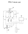
- Fig. 5 is a block diagram showing the outline of a conventional differential refractive index detector for a liquid chromatograph. as disclosed in Shodex, Operation Manual, No. 858 August, 1984 and which discloses the closest prior art.
- a conventional differential refractive index detector comprises two cells 11 and 12 consisting of a reference cell 11 for filling with or passage of a reference solution and a sample cell 12 through which a solution containing a sample is passed. These cells 11 and 12 are disposed such that their slant faces oppose each other.
- the sample cell 12 is connected by an eluent inlet line 14 for introducing an eluent eluted from a separation column 13 and by a sample cell outlet line 15.
- the reference cell 11 is connected by a reference cell inlet line 16 communicating with the sample cell outlet line 15 and by a reference cell outlet line 17.
- a three-way solenoid valve 19 is provided at the connection between the reference cell outlet line 17 and a line 18 externally extended from the connection of the sample outlet line 15 with the reference cell inlet line 16.
- an eluent outlet line 20 for discharging the eluent outside is connected to this three-way solenoid valve 19.
- a light source 21 for irradiating a measuring beam is provided, and on the other side, a reflector 22 for reflecting the measuring beam transmitted through these cells 11 and 12 is provided. Furthermore, in the vicinity of the light source 21, a photoreceptor device for detecting the displacement of the measuring beam accompanying the difference in the refractive index of the eluent in the two cells 11 and 12 is provided.
- the light source 21, the photoreceptor device 23 and the three-way solenoid valve 19 converge at a signal processing part 24.
- the signal processing part 24 has a function of outputting the difference in refractive index of the eluent into two cells 11 and 12 as an electric signal based on a signal sent from the photoreceptor device 23 and at the same time, controlling the driving of three-way solenoid valve 19 and the driving of light source 21 based on an operation signal sent from the outside.
- the differential refractive index detector can be stabilized in an analysis capable condition.
- the change in the refractive index of the eluent causes a serious problem.
- the refractive index of the eluent changes not only with the elution of a sample but also by the staining of eluent itself, the dissolved gas concentration, the temperature and the like.
- the judgement that the differential refractive index detector has reached a stable condition is made by intuition in many cases and greatly depends on the experience and skill of the judging person. This naturally brings about great personal errors in the judgement of stable condition. Depending on the case, the condition may be excessively stable or may be deficient in stability. Thus, this intuitive judgement is disadvantageous in that an efficient operation cannot be attained.
- the present invention was developed in order to solve the problems described above. It is an object of the present invention to provide a differential refractive index detector in which the processing from an initial solution purge operation of intermittently introducing an eluent into a referential cell until a stability confirming operation of confirming that the differential refractive index detector has stabilized in an analysis capable condition are automated, thereby eliminating fears for personal errors in the judgement of stable condition and enabling a highly efficient analysis operation, and also to provide a liquid chromatograph equipped with the detector.
- means for announcing that the detector has stabilized in the analysis capable condition is provided, so that the operator can swiftly know that the detector has stabilized in the analysis capable condition and can efficiently perform the analysis work.
- the processing from the initial solution purge operation of introducing an eluent into a reference cell until the stability confirming operation of stabilizing the differential refractive index detector into the analysis capable condition can be automated and thereby a highly efficient analysis operation can be attained.
- the liquid chromatograph of the present invention is characterized by being equipped with the differential refractive index detector of the present invention.
- a differential refractive index detector of the present invention is provided, so that the reference cell and the sample cell can be automatically and swiftly stabilized without any participation from an operator and the liquid chromatography can be more efficiently performed.
- the differential refractive index detector of the present invention when applied to a liquid chromatograph, the analysis operation of liquid chromatography can be performed with remarkably high efficiency.
- Figure 1 is a block diagram showing the signal processing part forming an important part of a differential refractive index detector for a liquid chromatograph according to one embodiment of the present invention.
- the numeral 1 is an A/D converter where an analog signal corresponding to the displacement of optical axis of light transmitted through a reference cell and a sample cell accompanying the difference in refractive index of the reference solution and the sample solution is output from the photoreceptor device (detection part) not shown and converted into a digital signal;
- 2 is a digital computer for applying predetermined processing on the digital signal output from the A/D converter 1;
- 3 is a D/A converter where the digital signal as a result of processing is output from the digital computer and converted into an analog signal to output it as an output signal.
- the numeral 4 is an input unit for inputting parameters such as respective limits of drift value and noise value or giving indications relating to the operations such as actuation or stopping and also for inputting input data or the like into the digital computer 2;
- 5 is an output unit for outputting the processing result output from the digital computer 2 with respect to the operating state, for example, whether or not the detector has stabilized in a analysis capable condition;
- 6 is a three-way solenoid valve driving circuit for driving a three-way solenoid valve by switching over the flow passage of eluent to the reference cell or sample cell; and 7 is a light source driving circuit for driving a light source not shown.
- the output unit 5 has announcing means for announcing that the detector has stabilized in an analysis capable condition when it is confirmed in the stability confirming operation and also for announcing that the condition where the drift value described later is larger than the drift limit and/or the noise value is larger than the noise limit is continuing in excess of a predetermined time.
- the announcing means is a display unit such as display, an acoustic unit of making announcement by sound or an audio unit of making announcement by voice. Also, a unit of making the announcement by vibration or the like may be mounted as the announcing means.
- the digital computer 2 stores a program (means) 8 as a previously established time series procedure.
- the eluent passed through the sample cell at the start of operation of detector is intermittently passed through the reference cell according to the previously established time series procedure to eliminate bubbles in the sample cell and the reference cell and also to roughly perform the eluent purge.
- a drift value and a noise value are determined from a signal corresponding to the difference in refractive index based on the signal sent from the photoreceptor device. These values are compared with a previously set drift limit and a noise limit and when the drift value is smaller than the drift limit and at the same time, the noise value is smaller than the noise limit, the eluent passed through the sample cell is stopped from passing through the reference cell. When the drift value is larger than the drift limit and/or the noise value is larger than the noise limit, the comparison operation is again performed.
- a drift value and a noise value are determined from a signal corresponding to the difference in refractive index based on the signal from the photoreceptor device. These values are compared with previously set drift limit and noise limit and when the drift value is smaller than the drift limit and at the same time, the noise value is smaller than the noise limit, the detector is judged to have stabilized in the analysis capable condition. When the drift value is larger than the drift limit and/or the noise value is larger than the noise limit, the comparison operation is again performed.
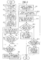
- SP1 Electric power is charged (SP1) and when a START signal is inputted from the input unit 4 (SP2), the three-way solenoid valve driving circuit 6 is driven to flush the three-way solenoid valve and allow the eluent passed through from the sample cell to intermittently pass through the reference cell, whereby bubbles in the sample cell and the reference cell are eliminated and also rough eluent purge is attained (SP3).
- the three-way solenoid valve driving circuit is driven to open the three-way solenoid valve and continuously pass the eluent which has flowed out from the sample cell through the reference cell (SP4).
- a drift value and a noise value are calculated by a signal corresponding to the difference in refractive index based on the signal sent from a photoreceptor device not shown (SP5).
- the drift value and the noise value calculated are compared with the drift limit and the noise limit which are previously input by the input unit 4 (SP6).
- the three-way solenoid valve driving circuit 6 is driven to switch the flow passage and stop the flow of eluent into the reference cell (SP7).
- the eluent is continuously passed through the sample cell (SP10) and in this state, a drift value and a noise value are calculated from a signal corresponding to the difference in refractive index based on the signal sent from the photoreceptor device not shown (SP11).
- the drift value and the noise value calculated are compared with the drift limit and the noise limit previously input by the input unit 24 (SP12).
- the announcing means announces that the detector has reached a condition capable of analysis (SP13) and the work is terminated.
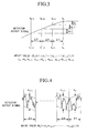
- an output signal value is measured at predetermined time intervals delta T (for example, from 3 to 15 minutes) and an absolute value of the difference between the output signal value at the time concerned and the output signal value at the preceding time is calculated and stored as the this-time value.
- the value calculated last time is stored as the last-time value
- the value calculated before last time is as the before-last-time value.
- a simple average of these this-time value, last-time value and before-last-time value is defined as the drift value at the time concerned.
- the drift value at the time concerned may be a smoothed value obtained using a smoothing constant.
- the output signal value at each measurement time may be an average of a plurality of measurements so as to reduce the dispersion in the measurement.
- instantaneous noise values are obtained in a plurality of blocks (k+1 blocks, wherein k is an integer satisfying, for example, 9 ⁇ k ⁇ 29) divided at predetermined time intervals delta t (for example, from 0.5 to 1 minute) and an average of the instantaneous noise values obtained is defined as the noise value at the time concerned.
- straight lines are drawn to include the minimum output signal value in a block and at the same time contact with one or more other output signal value. Out of these straight lines, a straight line having a smallest absolute value of gradient is picked up and on taking account of the relationship between this straight line and the output signal, a maximum value among absolute values of the difference at the same time instant is determined. Similarly, straight lines are drawn to include the maximum output signal value in a block and at the same time contact with one or more other output signal value. Out of these straight lines, a straight line having a smallest absolute value of gradient is picked up and on taking account of the relationship between this straight line and the output signal, a maximum value among absolute values of the difference at the same time instant is determined. A larger value of these values determined is defined as the instantaneous noise value of the block concerned. It is also possible to use a smaller value of the maximum values determined as the instantaneous noise value.
- a program is stored in the digital computer 22, which is composed such that an initial solution purge operation of performing eluent purge by intermittently passing an eluent flown out from the sample cell through the reference cell at the start of operation of the detector, a stabilizing solution purge operation of allowing the eluent purge of the sample cell and the reference cell to proceed and at the same time, confirming the stable condition thereof, and a stability confirming operation of confirming whether or not said detector has stabilized in the analysis capable condition by passing the eluent only through the sample cell are sequentially undertaken. Therefore, the processing from the initial solution purge operation until the stability confirming operation can be automated and a highly efficient analysis operation can be attained.
- the differential refractive index detector of this embodiment when applied to a detector of liquid chromatograph, the detector can be automatically and swiftly stabilized without requiring any participation from an operator. Therefore, the analysis operation of liquid chromatography can be performed with remarkably high efficiency.
- differential refractive index detector according to one embodiment of the present invention is described with reffering to the drawings, however, the specific structure thereof is by no means limited to this embodiment and any change can be made in the design as long as it does not depart from the spirit and scope of the present invention.
- the width of predetermined time intervals delta T or delta t used in the calculation method of drift value or noise value, or the number of absolute values of difference used for the simple averaging may be appropriately changed according to the apparatus to which the detector is applied.
Landscapes
- Physics & Mathematics (AREA)
- Health & Medical Sciences (AREA)
- Life Sciences & Earth Sciences (AREA)
- Chemical & Material Sciences (AREA)
- Analytical Chemistry (AREA)
- Biochemistry (AREA)
- General Health & Medical Sciences (AREA)
- General Physics & Mathematics (AREA)
- Immunology (AREA)
- Pathology (AREA)
- Spectroscopy & Molecular Physics (AREA)
- Investigating Or Analysing Materials By Optical Means (AREA)
- Optical Measuring Cells (AREA)
- Organic Low-Molecular-Weight Compounds And Preparation Thereof (AREA)
Claims (7)
- Détecteur différentiel d'indice de réfraction comprenant une cellule de référence (11) pour introduire ou transférer une solution de référence, une cellule à échantillon (12) pour transférer une solution contenant un échantillon, des moyens de commutation (19) pour permettre à un éluant, qui est sorti de la cellule à échantillon (12), de pénétrer de façon intermittente dans la cellule de référence (11), une source de lumière (21) pour projeter une lumière sur lesdites deux cellules (11,12), une partie de détection (23) pour détecter une lumière transmise par les cellules respectives (11,12), une partie (24) de traitement de signal pour appliquer un traitement prédéterminé à un signal de sortie envoyé par ladite partie de détection (23), caractérisé par :des moyens (8) pour exécuter séquentiellement(a) une opération de purge initial de la solution pour réaliser la purge de ladite cellule à échantillon (12) et de ladite cellule de référence (11) avec un éluant au moyen du passage de l'éluant à travers les cellules (11,12) lors du démarrage du fonctionnement dudit détecteur,(b) une opération de purge d'une solution de stabilisation pour permettre d'exécuter la purge de l'éluant de ladite cellule à échantillon (12) et de ladite cellule de référence (11) et, simultanément, pour confirmer la condition stable de ces cellules, et
dans lequel les moyens pour exécuter l'opération de purge de la solution de stabilisation comprennentdes moyens pour obtenir une valeur de dérive et une valeur de bruit à partir dudit signal de sortie, alors que les moyens de commutation (19) sont dans un état permettant l'écoulement de l'éluant depuis la cellule à échantillon (12) dans la cellule de référence (11),des moyens pour comparer les valeurs obtenues avec une limite de dérive et une limite de bruit réglées au préalable, etdes moyens pouri) soit empêcher l'éluant qui a traversé ladite cellule à échantillon (12) de traverser ladite cellule de référence (11) lorsque ladite valeur de dérive est inférieure à ladite limite de dérive et que simultanément ladite valeur de bruit est inférieure à ladite limite de bruit,ii) soit exécuter à nouveau l'opération d'obtention de ladite valeur de dérive et de ladite valeur de bruit et comparer ces valeurs à la limite de dérive et à la limite de bruit réglées antérieurement lorsque ladite valeur de dérive est supérieure à ladite limite de dérive et/ou que ladite valeur de bruit est supérieure à ladite limite de bruit,(c) une opération de confirmation de stabilité destinée à confirmer si ledit détecteur s'est stabilisé ou non dans une condition permettant une analyse, par passage dudit éluant uniquement dans ladite cellule à échantillon (12), et dans lequel le dispositif comprend en outredes moyens pour annoncer que ledit détecteur s'est stabilisé dans 1a condition permettant l'analyse. - Détecteur selon la revendication 1, dans lequel des moyens sont prévus pour activer les moyens (19) pour le passage intermittent d'un éluant ayant traversé ladite cellule à échantillon conformément à une procédure en série dans le temps, réglée au préalable, pendant l'opération de purge initiale de la solution.
- Détecteur selon la revendication 1 ou 2, dans lequel les moyens d'exécution de l'opération de confirmation de stabilité comprennent des moyens pour obtenir une valeur de dérive et une valeur de bruit à partir dudit signal de sortie, alors que l'éluant traverse uniquement ladite cellule à échantillon (12), des moyens pour comparer les valeurs obtenues à une limite de dérive et à une limite de bruit réglées précédemment, et des moyens pouri) soit évaluer que le détecteur s'est stabilisé dans la condition permettant l'analyse lorsque ladite valeur de dérive est inférieure à ladite limite de dérive et que simultanément, ladite valeur de bruit est inférieure à ladite limite de bruit,ii) soit exécuter à nouveau l'opération d'obtention de ladite valeur de dérive et de ladite valeur de bruit et comparer ces valeurs, lorsque ladite valeur de dérive est supérieure à ladite limite de dérive et/ou que ladite valeur de bruit est supérieure à ladite limite de bruit.
- Détecteur selon l'une quelconque des revendications précédentes, comprenant en outre des moyens pour annoncer que l'état, dans lequel ladite valeur de dérive est supérieure à ladite limite de dérive et/ou ladite valeur de bruit est supérieure à ladite limite de bruit, s'est maintenu au-delà d'un intervalle de temps prédéterminé.
- Détecteur selon la revendication 3 ou 4, comprenant en outre des moyens pour obtenir une valeur de dérive par mesure de la valeur dudit signal de sortie à des intervalles de temps prédéterminés, calcul d'une valeur absolue de la différence entre la valeur du signal de sortie à l'instant considéré et la valeur du signal de sortie à un instant précédent, et formation de la moyenne des valeurs absolues calculées.
- Détecteur selon la revendication 3 ou 4, comprenant en outre des moyens pour obtenir ladite valeur de bruit par formation de la moyenne de valeurs de bruit instantanées respectives d'une pluralité de blocs divisés à des intervalles de temps prédéterminés.
- Chromatographe en phase liquide équipé du détecteur différentiel d'indice de réfraction décrit dans l'une quelconque des revendications précédentes.
Applications Claiming Priority (2)
| Application Number | Priority Date | Filing Date | Title |
|---|---|---|---|
| JP20997899 | 1999-07-23 | ||
| JP20997899A JP3574010B2 (ja) | 1999-07-23 | 1999-07-23 | 示差屈折率検出器及びそれを備えた液体クロマトグラフ装置 |
Publications (3)
| Publication Number | Publication Date |
|---|---|
| EP1070957A2 EP1070957A2 (fr) | 2001-01-24 |
| EP1070957A3 EP1070957A3 (fr) | 2002-04-03 |
| EP1070957B1 true EP1070957B1 (fr) | 2005-11-23 |
Family
ID=16581841
Family Applications (1)
| Application Number | Title | Priority Date | Filing Date |
|---|---|---|---|
| EP00104840A Expired - Lifetime EP1070957B1 (fr) | 1999-07-23 | 2000-03-07 | Réfractomètre différentiel et chromatographe en phase liquide ainsi équipé |
Country Status (4)
| Country | Link |
|---|---|
| EP (1) | EP1070957B1 (fr) |
| JP (1) | JP3574010B2 (fr) |
| AT (1) | ATE310947T1 (fr) |
| DE (1) | DE60024176T2 (fr) |
Families Citing this family (3)
| Publication number | Priority date | Publication date | Assignee | Title |
|---|---|---|---|---|
| JP4656018B2 (ja) * | 2006-07-28 | 2011-03-23 | 株式会社島津製作所 | 示差屈折率検出器 |
| JP5333089B2 (ja) * | 2009-09-09 | 2013-11-06 | 株式会社島津製作所 | クロマトグラフ用データ処理装置 |
| JP6604677B1 (ja) * | 2019-04-05 | 2019-11-13 | 日本分光株式会社 | 示差屈折率の測定方法、測定装置、および、測定プログラム |
Family Cites Families (3)
| Publication number | Priority date | Publication date | Assignee | Title |
|---|---|---|---|---|
| US2810315A (en) * | 1953-05-11 | 1957-10-22 | Phillips Petroleum Co | Differential refractometer cell assembly |
| FR2459470B1 (fr) * | 1979-06-20 | 1985-06-21 | Waters Associates Inc | Dispositif de mesure de la deviation d'un faisceau lumineux |
| JP2504356B2 (ja) * | 1992-04-09 | 1996-06-05 | 株式会社島津製作所 | 示差屈折計 |
-
1999
- 1999-07-23 JP JP20997899A patent/JP3574010B2/ja not_active Expired - Lifetime
-
2000
- 2000-03-07 EP EP00104840A patent/EP1070957B1/fr not_active Expired - Lifetime
- 2000-03-07 DE DE60024176T patent/DE60024176T2/de not_active Expired - Lifetime
- 2000-03-07 AT AT00104840T patent/ATE310947T1/de not_active IP Right Cessation
Also Published As
| Publication number | Publication date |
|---|---|
| JP2001033386A (ja) | 2001-02-09 |
| DE60024176T2 (de) | 2006-08-03 |
| EP1070957A3 (fr) | 2002-04-03 |
| ATE310947T1 (de) | 2005-12-15 |
| JP3574010B2 (ja) | 2004-10-06 |
| EP1070957A2 (fr) | 2001-01-24 |
| DE60024176D1 (de) | 2005-12-29 |
Similar Documents
| Publication | Publication Date | Title |
|---|---|---|
| US3826905A (en) | Methods and apparatus for providing automatic control of chromatographic fractionating processes | |
| JP4775937B2 (ja) | 近赤外線分光器を利用したリソグラフィ工程用組成物の実時間制御システム及びその制御方法 | |
| JPH05288737A (ja) | ガスクロマトグラフ装置 | |
| US20090049891A1 (en) | Supercritical-Phase Mixed Chromatography Method and Installation for Implementing Same | |
| US6295125B1 (en) | Differential refractive index detector and liquid chromatograph equipped with the same | |
| EP1070957B1 (fr) | Réfractomètre différentiel et chromatographe en phase liquide ainsi équipé | |
| US4991428A (en) | Ion chromatography method for low concentrations | |
| AU711415B2 (en) | Multi-cycle loop injection for trace analysis by ion chromatography apparatus and method | |
| JP2648326B2 (ja) | ポリマーの分別測定装置 | |
| US4972730A (en) | System for dosing and determining saturation pressure in a volumetric sorption analyzer | |
| JPS61194336A (ja) | 自動化学分析装置 | |
| US5042293A (en) | Ion chromatography method for low concentrations | |
| CN107153120A (zh) | 样本分析仪及样本分析仪的样本载入控制方法 | |
| JPH0755780A (ja) | ガスクロマトグラフによる各種ガス中の超微量成分の高感度測定装置 | |
| JPH08271491A (ja) | ガスクロマトグラフ装置 | |
| JP2006527370A (ja) | 並列プロセスを実行する装置および方法 | |
| JPH10300734A (ja) | ガスクロマトグラフ装置 | |
| JP2001324445A (ja) | 表面プラズモン共鳴角測定における試料濃度予測方法 | |
| JPH049750A (ja) | 恒温槽浸漬型分析装置 | |
| US5914607A (en) | Apparatus and methods for analyzing a sample solution, including first and second ion detectors | |
| JPH05227943A (ja) | 自動培養装置 | |
| CN117110014A (zh) | 一种气体稀释进样装置 | |
| JPH04157185A (ja) | 自動液管理装置 | |
| JPH10300735A (ja) | クロマトグラフィーの試料導入条件決定法 | |
| JP2006162262A (ja) | 示差屈折率検出器 |
Legal Events
| Date | Code | Title | Description |
|---|---|---|---|
| PUAI | Public reference made under article 153(3) epc to a published international application that has entered the european phase |
Free format text: ORIGINAL CODE: 0009012 |
|
| AK | Designated contracting states |
Kind code of ref document: A2 Designated state(s): AT BE CH CY DE DK ES FI FR GB GR IE IT LI LU MC NL PT SE |
|
| AX | Request for extension of the european patent |
Free format text: AL;LT;LV;MK;RO;SI |
|
| PUAL | Search report despatched |
Free format text: ORIGINAL CODE: 0009013 |
|
| AK | Designated contracting states |
Kind code of ref document: A3 Designated state(s): AT BE CH CY DE DK ES FI FR GB GR IE IT LI LU MC NL PT SE |
|
| AX | Request for extension of the european patent |
Free format text: AL;LT;LV;MK;RO;SI |
|
| 17P | Request for examination filed |
Effective date: 20020920 |
|
| AKX | Designation fees paid |
Free format text: AT BE CH CY DE DK ES FI FR GB GR IE IT LI LU MC NL PT SE |
|
| 17Q | First examination report despatched |
Effective date: 20030128 |
|
| GRAP | Despatch of communication of intention to grant a patent |
Free format text: ORIGINAL CODE: EPIDOSNIGR1 |
|
| GRAS | Grant fee paid |
Free format text: ORIGINAL CODE: EPIDOSNIGR3 |
|
| GRAA | (expected) grant |
Free format text: ORIGINAL CODE: 0009210 |
|
| AK | Designated contracting states |
Kind code of ref document: B1 Designated state(s): AT BE CH CY DE DK ES FI FR GB GR IE IT LI LU MC NL PT SE |
|
| PG25 | Lapsed in a contracting state [announced via postgrant information from national office to epo] |
Ref country code: IT Free format text: LAPSE BECAUSE OF FAILURE TO SUBMIT A TRANSLATION OF THE DESCRIPTION OR TO PAY THE FEE WITHIN THE PRESCRIBED TIME-LIMIT;WARNING: LAPSES OF ITALIAN PATENTS WITH EFFECTIVE DATE BEFORE 2007 MAY HAVE OCCURRED AT ANY TIME BEFORE 2007. THE CORRECT EFFECTIVE DATE MAY BE DIFFERENT FROM THE ONE RECORDED. Effective date: 20051123 Ref country code: LI Free format text: LAPSE BECAUSE OF FAILURE TO SUBMIT A TRANSLATION OF THE DESCRIPTION OR TO PAY THE FEE WITHIN THE PRESCRIBED TIME-LIMIT Effective date: 20051123 Ref country code: FI Free format text: LAPSE BECAUSE OF FAILURE TO SUBMIT A TRANSLATION OF THE DESCRIPTION OR TO PAY THE FEE WITHIN THE PRESCRIBED TIME-LIMIT Effective date: 20051123 Ref country code: AT Free format text: LAPSE BECAUSE OF FAILURE TO SUBMIT A TRANSLATION OF THE DESCRIPTION OR TO PAY THE FEE WITHIN THE PRESCRIBED TIME-LIMIT Effective date: 20051123 Ref country code: NL Free format text: LAPSE BECAUSE OF FAILURE TO SUBMIT A TRANSLATION OF THE DESCRIPTION OR TO PAY THE FEE WITHIN THE PRESCRIBED TIME-LIMIT Effective date: 20051123 Ref country code: BE Free format text: LAPSE BECAUSE OF FAILURE TO SUBMIT A TRANSLATION OF THE DESCRIPTION OR TO PAY THE FEE WITHIN THE PRESCRIBED TIME-LIMIT Effective date: 20051123 Ref country code: CH Free format text: LAPSE BECAUSE OF FAILURE TO SUBMIT A TRANSLATION OF THE DESCRIPTION OR TO PAY THE FEE WITHIN THE PRESCRIBED TIME-LIMIT Effective date: 20051123 |
|
| REG | Reference to a national code |
Ref country code: GB Ref legal event code: FG4D |
|
| REG | Reference to a national code |
Ref country code: CH Ref legal event code: EP |
|
| REF | Corresponds to: |
Ref document number: 60024176 Country of ref document: DE Date of ref document: 20051229 Kind code of ref document: P |
|
| REG | Reference to a national code |
Ref country code: IE Ref legal event code: FG4D |
|
| PG25 | Lapsed in a contracting state [announced via postgrant information from national office to epo] |
Ref country code: DK Free format text: LAPSE BECAUSE OF FAILURE TO SUBMIT A TRANSLATION OF THE DESCRIPTION OR TO PAY THE FEE WITHIN THE PRESCRIBED TIME-LIMIT Effective date: 20060223 Ref country code: GR Free format text: LAPSE BECAUSE OF FAILURE TO SUBMIT A TRANSLATION OF THE DESCRIPTION OR TO PAY THE FEE WITHIN THE PRESCRIBED TIME-LIMIT Effective date: 20060223 Ref country code: SE Free format text: LAPSE BECAUSE OF FAILURE TO SUBMIT A TRANSLATION OF THE DESCRIPTION OR TO PAY THE FEE WITHIN THE PRESCRIBED TIME-LIMIT Effective date: 20060223 |
|
| PG25 | Lapsed in a contracting state [announced via postgrant information from national office to epo] |
Ref country code: ES Free format text: LAPSE BECAUSE OF FAILURE TO SUBMIT A TRANSLATION OF THE DESCRIPTION OR TO PAY THE FEE WITHIN THE PRESCRIBED TIME-LIMIT Effective date: 20060306 |
|
| PG25 | Lapsed in a contracting state [announced via postgrant information from national office to epo] |
Ref country code: IE Free format text: LAPSE BECAUSE OF NON-PAYMENT OF DUE FEES Effective date: 20060307 |
|
| PG25 | Lapsed in a contracting state [announced via postgrant information from national office to epo] |
Ref country code: LU Free format text: LAPSE BECAUSE OF NON-PAYMENT OF DUE FEES Effective date: 20060331 Ref country code: MC Free format text: LAPSE BECAUSE OF NON-PAYMENT OF DUE FEES Effective date: 20060331 |
|
| PG25 | Lapsed in a contracting state [announced via postgrant information from national office to epo] |
Ref country code: PT Free format text: LAPSE BECAUSE OF FAILURE TO SUBMIT A TRANSLATION OF THE DESCRIPTION OR TO PAY THE FEE WITHIN THE PRESCRIBED TIME-LIMIT Effective date: 20060424 |
|
| NLV1 | Nl: lapsed or annulled due to failure to fulfill the requirements of art. 29p and 29m of the patents act | ||
| REG | Reference to a national code |
Ref country code: CH Ref legal event code: PL |
|
| ET | Fr: translation filed | ||
| PLBE | No opposition filed within time limit |
Free format text: ORIGINAL CODE: 0009261 |
|
| STAA | Information on the status of an ep patent application or granted ep patent |
Free format text: STATUS: NO OPPOSITION FILED WITHIN TIME LIMIT |
|
| 26N | No opposition filed |
Effective date: 20060824 |
|
| REG | Reference to a national code |
Ref country code: IE Ref legal event code: MM4A |
|
| PG25 | Lapsed in a contracting state [announced via postgrant information from national office to epo] |
Ref country code: CY Free format text: LAPSE BECAUSE OF FAILURE TO SUBMIT A TRANSLATION OF THE DESCRIPTION OR TO PAY THE FEE WITHIN THE PRESCRIBED TIME-LIMIT Effective date: 20051123 |
|
| REG | Reference to a national code |
Ref country code: GB Ref legal event code: 732E Free format text: REGISTERED BETWEEN 20111201 AND 20111207 |
|
| REG | Reference to a national code |
Ref country code: FR Ref legal event code: TQ Owner name: SHOKO SCIENTIFIC CO., LTD, JP Effective date: 20111208 Ref country code: FR Ref legal event code: TQ Owner name: ERC INC., JP Effective date: 20111208 |
|
| REG | Reference to a national code |
Ref country code: DE Ref legal event code: R082 Ref document number: 60024176 Country of ref document: DE Representative=s name: STREHL, SCHUEBEL-HOPF & PARTNER, DE |
|
| REG | Reference to a national code |
Ref country code: DE Ref legal event code: R081 Ref document number: 60024176 Country of ref document: DE Owner name: ERC INC., JP Free format text: FORMER OWNER: SHOWA DENKO K.K., ERC INC., , JP Effective date: 20120306 Ref country code: DE Ref legal event code: R082 Ref document number: 60024176 Country of ref document: DE Representative=s name: PATENTANWAELTE STREHL, SCHUEBEL-HOPF & PARTNER, DE Effective date: 20120306 Ref country code: DE Ref legal event code: R081 Ref document number: 60024176 Country of ref document: DE Owner name: SHOKO SCIENTIFIC CO., LTD., JP Free format text: FORMER OWNER: SHOWA DENKO K.K., ERC INC., , JP Effective date: 20120306 Ref country code: DE Ref legal event code: R081 Ref document number: 60024176 Country of ref document: DE Owner name: SHOKO SCIENTIFIC CO., LTD., JP Free format text: FORMER OWNER: SHOKO SCIENTIFIC CO., LTD., YOKOHAMA, JP Effective date: 20120315 Ref country code: DE Ref legal event code: R081 Ref document number: 60024176 Country of ref document: DE Owner name: ERC INC., JP Free format text: FORMER OWNER: SHOKO SCIENTIFIC CO., LTD., YOKOHAMA, JP Effective date: 20120315 Ref country code: DE Ref legal event code: R082 Ref document number: 60024176 Country of ref document: DE Representative=s name: PATENTANWAELTE STREHL, SCHUEBEL-HOPF & PARTNER, DE Effective date: 20120315 Ref country code: DE Ref legal event code: R081 Ref document number: 60024176 Country of ref document: DE Owner name: SHOKO SCIENTIFIC CO., LTD., YOKOHAMA, JP Free format text: FORMER OWNER: SHOKO SCIENTIFIC CO., LTD., YOKOHAMA, KANAGAWA, JP Effective date: 20120315 Ref country code: DE Ref legal event code: R081 Ref document number: 60024176 Country of ref document: DE Owner name: ERC INC., KAWAGUCHI, JP Free format text: FORMER OWNER: SHOWA DENKO K.K., ERC INC., , JP Effective date: 20120306 Ref country code: DE Ref legal event code: R081 Ref document number: 60024176 Country of ref document: DE Owner name: ERC INC., KAWAGUCHI, JP Free format text: FORMER OWNER: SHOKO SCIENTIFIC CO., LTD., YOKOHAMA, KANAGAWA, JP Effective date: 20120315 Ref country code: DE Ref legal event code: R081 Ref document number: 60024176 Country of ref document: DE Owner name: SHOKO SCIENTIFIC CO., LTD., YOKOHAMA, JP Free format text: FORMER OWNER: SHOWA DENKO K.K., ERC INC., , JP Effective date: 20120306 Ref country code: DE Ref legal event code: R081 Ref document number: 60024176 Country of ref document: DE Owner name: SHOKO SCIENTIFIC CO., LTD., YOKOHAMA, JP Free format text: FORMER OWNERS: SHOWA DENKO K.K., TOKIO/TOKYO, JP; ERC INC., KAWAGUCHI, SAITAMA, JP Effective date: 20120306 Ref country code: DE Ref legal event code: R081 Ref document number: 60024176 Country of ref document: DE Owner name: ERC INC., KAWAGUCHI, JP Free format text: FORMER OWNERS: SHOWA DENKO K.K., TOKIO/TOKYO, JP; ERC INC., KAWAGUCHI, SAITAMA, JP Effective date: 20120306 Ref country code: DE Ref legal event code: R082 Ref document number: 60024176 Country of ref document: DE Representative=s name: STREHL SCHUEBEL-HOPF & PARTNER MBB PATENTANWAE, DE Effective date: 20120315 Ref country code: DE Ref legal event code: R082 Ref document number: 60024176 Country of ref document: DE Representative=s name: STREHL SCHUEBEL-HOPF & PARTNER MBB PATENTANWAE, DE Effective date: 20120306 |
|
| REG | Reference to a national code |
Ref country code: FR Ref legal event code: PLFP Year of fee payment: 17 |
|
| REG | Reference to a national code |
Ref country code: FR Ref legal event code: PLFP Year of fee payment: 18 |
|
| REG | Reference to a national code |
Ref country code: FR Ref legal event code: PLFP Year of fee payment: 19 |
|
| PGFP | Annual fee paid to national office [announced via postgrant information from national office to epo] |
Ref country code: GB Payment date: 20190306 Year of fee payment: 20 Ref country code: DE Payment date: 20190219 Year of fee payment: 20 |
|
| PGFP | Annual fee paid to national office [announced via postgrant information from national office to epo] |
Ref country code: FR Payment date: 20190213 Year of fee payment: 20 |
|
| REG | Reference to a national code |
Ref country code: DE Ref legal event code: R071 Ref document number: 60024176 Country of ref document: DE |
|
| REG | Reference to a national code |
Ref country code: GB Ref legal event code: PE20 Expiry date: 20200306 |
|
| PG25 | Lapsed in a contracting state [announced via postgrant information from national office to epo] |
Ref country code: GB Free format text: LAPSE BECAUSE OF EXPIRATION OF PROTECTION Effective date: 20200306 |