EP1070817A2 - Rahmenteil eines Tür- oder Fensterbandes - Google Patents
Rahmenteil eines Tür- oder Fensterbandes Download PDFInfo
- Publication number
- EP1070817A2 EP1070817A2 EP00114468A EP00114468A EP1070817A2 EP 1070817 A2 EP1070817 A2 EP 1070817A2 EP 00114468 A EP00114468 A EP 00114468A EP 00114468 A EP00114468 A EP 00114468A EP 1070817 A2 EP1070817 A2 EP 1070817A2
- Authority
- EP
- European Patent Office
- Prior art keywords
- frame part
- insert
- frame
- part according
- screw
- Prior art date
- Legal status (The legal status is an assumption and is not a legal conclusion. Google has not performed a legal analysis and makes no representation as to the accuracy of the status listed.)
- Granted
Links
Images



Classifications
-
- E—FIXED CONSTRUCTIONS
- E05—LOCKS; KEYS; WINDOW OR DOOR FITTINGS; SAFES
- E05D—HINGES OR SUSPENSION DEVICES FOR DOORS, WINDOWS OR WINGS
- E05D9/00—Flaps or sleeves specially designed for making from particular material, e.g. hoop-iron, sheet metal, plastics
-
- E—FIXED CONSTRUCTIONS
- E05—LOCKS; KEYS; WINDOW OR DOOR FITTINGS; SAFES
- E05D—HINGES OR SUSPENSION DEVICES FOR DOORS, WINDOWS OR WINGS
- E05D5/00—Construction of single parts, e.g. the parts for attachment
- E05D5/02—Parts for attachment, e.g. flaps
- E05D5/04—Flat flaps
-
- E—FIXED CONSTRUCTIONS
- E05—LOCKS; KEYS; WINDOW OR DOOR FITTINGS; SAFES
- E05Y—INDEXING SCHEME ASSOCIATED WITH SUBCLASSES E05D AND E05F, RELATING TO CONSTRUCTION ELEMENTS, ELECTRIC CONTROL, POWER SUPPLY, POWER SIGNAL OR TRANSMISSION, USER INTERFACES, MOUNTING OR COUPLING, DETAILS, ACCESSORIES, AUXILIARY OPERATIONS NOT OTHERWISE PROVIDED FOR, APPLICATION THEREOF
- E05Y2900/00—Application of doors, windows, wings or fittings thereof
- E05Y2900/10—Application of doors, windows, wings or fittings thereof for buildings or parts thereof
- E05Y2900/13—Type of wing
- E05Y2900/132—Doors
-
- E—FIXED CONSTRUCTIONS
- E05—LOCKS; KEYS; WINDOW OR DOOR FITTINGS; SAFES
- E05Y—INDEXING SCHEME ASSOCIATED WITH SUBCLASSES E05D AND E05F, RELATING TO CONSTRUCTION ELEMENTS, ELECTRIC CONTROL, POWER SUPPLY, POWER SIGNAL OR TRANSMISSION, USER INTERFACES, MOUNTING OR COUPLING, DETAILS, ACCESSORIES, AUXILIARY OPERATIONS NOT OTHERWISE PROVIDED FOR, APPLICATION THEREOF
- E05Y2900/00—Application of doors, windows, wings or fittings thereof
- E05Y2900/10—Application of doors, windows, wings or fittings thereof for buildings or parts thereof
- E05Y2900/13—Type of wing
- E05Y2900/148—Windows
Definitions
- the invention relates to a frame part of a Door or window hinge, in particular a hinge, with a vertical screw-on strip on a frame, with the one vertically to the frame via the screw bar protruding axle support piece in one piece at a transition point is an axle receiving recess of a joint part with which a wing part on the axle mounting piece is supported.
- Door or window hinges serve to carry the burden of one Door or window sash on the frame of the door or to transfer the window. So you need to be trained so be that they meet the burdens imposed by the Wings originate, in particular from its weight and from the dynamic resulting from the movements of the wing Charges. Dynamic loads come in particular occurs when the wing moves unintentionally. To the Example occur when a door leaf closes large impulsive forces on which the door hinge must have grown. These dynamic loads work especially in the area of the transition from the screw bar in the axle mounting piece of the entry described Part of the frame.
- the invention is therefore based on the object To improve the frame part with the features mentioned at the beginning, that it also impulses like loads instantly withstands duration.
- This object is achieved in that at least that Axle support piece one of its transition point to the screw bar stiffening insert.
- a stiffening Insert the transition point between the axle support piece and the screw-on bar significantly stiffened.
- the invention Training is suitable for both tapes, at which a wing part with the frame part via a hinge pin is pivotally connected, as with one Turn-tilt band, in which the wing has both rotary movements can perform as well as tilting movements and the articulated Connection of the wing part with the frame part therefore accordingly is trained.
- the stiffening insert stabilizes the transition point, experience shows that the highest specific material loads occur, for example, caused by notch stresses.
- the formation of the insert is basically arbitrary, provided that it stabilizes the transition point described. However, it is advantageous to design the frame part in such a way that the insert both engages in the axle support piece, as well as in the screw bar. In this case the transition point with the insert from the axle support piece stabilized here, as well as from the screw-on bar forth. In the axle mounting piece and in the screw-on bar Sufficiently large areas to stabilize the insert here to be able to train.
- the frame part it is preferred to design the frame part so that the insert in a recess on the frame side open of the frame part is present and if necessary with a Frame contact surface of the frame part is aligned.
- the insert can be inserted into the open recess be, whereby the assembly of the frame part and the insert is simplified. If the insert on the frame side a frame contact surface of the frame part is aligned at the same time for optimal attachment or installation of the insert concerned about the frame. This also has an advantageous effect on the To stabilize the transition point between the Axle support piece and the screw bar of the frame part out.
- a particularly simple design of the frame part results when the insert is the transition point between the axle support piece and the screw bar overlapping plate or as a flat Plate is formed.
- the flat plate can, for example are made of tape material and is in any case to be mass-produced. In particular, it is sufficient the requirements for a deposit with different Sizes of the frame part are to be provided, in particular highlight a simple edit of their length is.
- a significant improvement in the stiffness of the Frame part can be achieved in that the insert in Axle support piece at least one vertical to the frame projecting stiffening projection.
- the stiffening projections stabilize the axle support piece in particular in areas where this itself is vertical to the Frame protrudes over the screw bar. This is This is particularly important for thin-walled frame parts or for those made of materials that are less resilient.
- the stiffening projections described above can improve the frame part so that the axle mounting piece a hinge pin receiving, parallel to the screw bar Has axle bore, and that the insert two has the axle bore has extensive stiffening projections. In order to optimally protruding stiffening projections are guaranteed. A stiffening of the axle support piece two mutually parallel stiffening projections increase the Resilience of the axle support piece accordingly.
- the frame part In line with the geometry of the axle support piece the frame part can be designed so that the stiffening projections formed as parallel plates are. As a result, the axle support piece despite the two existing stiffening projections kept narrow.
- the insert can be attached to the fastening requirements of the frame part be adjusted. For this purpose, it is trained that the insert with screw holes in the screw bar has aligned through holes. Consequently does not need to change the attachment of the frame part to become.
- the mounting screws are more common Screwed into the frame and press the Insert with the fastening leg against the frame. The presence of an insert affects the fastening process not from.
- the frame part can meet the respective operating conditions be adjusted in terms of fastenings by being so formed is that it is made of plastic or die-cast zinc and there is a metal or steel insert.
- a metal insert for example a sheet metal insert
- a more resilient Steel insert is provided.
- the frame part in such a way that the insert either through holes for Has support pins of the frame part or with the frame side Support pins is provided.
- the support pins can in the Frame frame intervene and take over supporting functions, otherwise the frame part must ensure that it has suitable support pins.
- the assembly the known support pins with the known frame parts not uncritical.
- the known frame parts have sufficient material length to the known support pins to enclose and on the other hand, the bracket of the known Support pins in the known frame parts by suitable constructive measures can be guaranteed, such as through shape environments at the ends of the support pins so that firmly connect them to the frame part.
- Arrangement of the support pins on the insert can both parts are better coordinated.
- the frame part is achieved in that the support pins as separately manufactured Parts are attached to the insert.
- the insert can be used as mass-produced part are manufactured and the Support pins are also conventional, namely made of metal and can be attached to the insert in a suitable manner e.g. by welding or riveting. This results in an attachment that the known Connection techniques in the known frame parts can be superior.
- the frame part is expediently formed such that the support pins at the level of the axle receiving piece available. So they are there where in the loads on the axle support piece in the immediate vicinity occur.
- the frame part is designed so that the insert is poured into the frame part.
- the frame part is thus in a conventional manner Injection molding.
- Cavity of an injection mold is made before the start of Injection molding arranged the insert and then directly with poured.
- the insert and the frame part are both inseparable from each other connected. So there can be no loss of Insert or for inserting the frame part without insert come.
- the deposit is at least one of the Screw bar parallel, on all sides of the material of the frame part surrounded pen is.
- the pen is an inexpensive one and part suitable for mass production, especially in the To be arranged near the transition point and here for one effective reinforcement.
- the frame part described above can preferably do so be further developed that as a deposit two each other parallel, extending from an outer surface of the frame part are extending pins. With two pens achieve an effective stiffening of the transition point, if the frame part is comparatively in this area is wide.
- the pins can be removed from the outer surface of the Frame part are used forth, for example by pressing.
- Another advantageous embodiment of the frame part arises when an angle piece is used as the insert is present, one of the angled legs in the screw bar and its other angle leg in the axle receiving piece intervenes.
- Such a deposit is in particular the usual training of an angular transition point optimally adapted.
- an angle leg of the insert one on an axle bore of the axle mounting piece has a coordinated recess.
- the axle support piece is also in the area around its axle bore reinforced around with the insert.
- Fastening the insert to the frame part is particularly important also advantageous to achieve that the Insert a mounting hole of a fixed on the frame part Fastener has. So here is an attachment between the insert and the frame part directly through an additional connecting element that is either part of the frame part, or that on the frame part for example by pressing, screwing or riveting is attached.
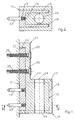
- the frame parts shown in the figures exist all from an axle receiving piece 13, which with a screw bar 12 is integrally formed and vertical projects to a frame 11 further than this Screw bar 12.
- the reason for this configuration is an axle bore 19, which is used to install a not shown Hinge pin is determined, with which also not
- the wing part shown can be pivoted on the frame part 10 is supported.
- the swivel axis of the wing part is 24 designated.
- the insert 15 is a flat plate 17th shown.
- the frame part 10 of the 3 shows a plate-shaped recess 16, the frame side is open, so that the insert 15 blind frame system side can be installed in the recess 16.
- the insert 15 and the frame part 10 produce that the insert 15 in the mold is installed. It is then from the material of the frame part 10 overmolded during its injection molding, so that a corresponding cohesion results, for example, by a suitable cross-sectional design of the plate 17 reinforced can be in which one of the edge surfaces a frame contact surface 10 'of the frame part 10 tapers.
- a suitable cross-sectional design of the plate 17 reinforced can be in which one of the edge surfaces a frame contact surface 10 'of the frame part 10 tapers.
- Such a tapering of an edge surface is shown in FIG 15 'of an insert 15 shown in dashed lines.
- the insert 15 In the manufacture of the frame part 10 is the installation the insert 15 in the injection mold of the frame part 10 unproblematic. Because the insert 15 has two Through holes 21, which are with the screw holes 20 of the Insert 15 must be aligned to the fastening screws 25 to be able to push through. To make the screw holes 20, however, retaining pins are required in the tool anyway, on which the insert 15 before the injection molding process is plugged on. The manufacture of the frame parts is accordingly simplified and certainly safer than if the assembly of the insert 15 and the frame part 10 after whose manufacture was carried out separately should be.
- Insert 15 of Figure 6 in its area with which it the screw bar 12 is used, also through holes 21 which are aligned with screw holes 20.
- the difference with this insert 15 is that it has reinforcing projections 18 has.
- These reinforcement tabs 18 extend into the area of FIG. 1, 2 Axle bore 19 of the axle support piece 13.
- Fig.2 shows that the stiffening projections 18, the axle receiving bore 19 reach around on both sides. They are each parallel to the bore Plates formed so that the insert 15 in the area of Axle bore 19 the U-shaped cross section shown in Figure 2 Has.
- the insert is in the area of the screw-on strip 12 15, on the other hand, is designed in the same way as a plate the Fig.4.
- the frame part 10 of Figure 5 is for receiving the Insert 15 of FIG. 6 with the recess 16 shown provided or this recess 16 is the space that during the assembly of the frame part 10 and the insert 15 is taken up by the latter.
- the support pins 23 shown in the figures are not in a way that differs from the prior art with the Frame part 10 connected directly, but with the insert 15.
- the insert 15 in the vertical region of the Axle receiving piece 13 pin receiving recesses 26, in the Fastening ends 23 'of the support pins 23 are installed.
- the 1,2 show a shape or longitudinal scoring of these ends, which is a sufficiently secure attachment with the insert 15 ensure.
- the support pins 23 jump from the insert 15 on the frame side so far that they are sufficient engage deep into the frame 11, as shown in Fig.1.
- For Absorption of the forces originating from the axle support piece 13 are two in one plane and in the plane of the fastening screws 25 support pins 23 arranged one above the other available.
- the support pins 23 can also be in on the insert 15 be attached differently.
- the support pins 23 with the deposits 15 are firmly connected by welding. This is then advantageous if the insert 15 with the frame part 10 is connected by injection molding and on the insert 15 no prefabricated bores 26 should be present.
- welding of the support pins 23 to the insert 15 is particularly unproblematic if the frame part 10 consists of zinc casting pressure, which with respect to the Welding heat load is not critical.
- All deposits apply that they are made from a material of the Frame part 10 must consist of coordinated material is suitable, which act on the axle receiving piece 13 To be able to absorb bending loads.
- the frame part 10 is injection-molded, for example, from plastic, it may be sufficient to produce the insert 15 from a sheet metal part, which is then, for example, an embossed part, which 6 has the shape with its projections 18 in particular to adequately stiffen the transition point 14.
- the frame part 10 is made of die-cast zinc it may be sufficient to insert the insert 15 as a flat plate 17 4 according to Figure 4, but which is sufficiently thick to the transition point 14 into the bending loads that occur to stiffen.
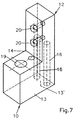
- Fig. 7 shows a frame part 10 in which two each other there are parallel recesses 16, which differ from one Bottom surface 13 'of the axle receiving piece 13 starting up to about extend into the middle of the screw bar 12.
- the two pin-shaped recesses 16 have the same distance from Transition point 14. Inserted into it, not shown Accordingly, pins also reinforce wider transition points reliable.
- the recesses 16 are arranged so that the Surround the pin on all sides by the material of the frame part 10 is.
- FIG 8 shows one in the vicinity of the transition point 14 of the frame part 10 arranged angular recess 16.
- the angle leg 27 is with Screw holes 20 for the passage of fastening screws 25 provided.
- Fig.9b Elbow has shown
- Angle piece in the angle leg 18 has a mounting hole 30, which is arranged so that it is under the wing part End face 31 of the axle receiving piece 13 is arranged is. Accordingly, the axle receiving piece 13 in its end face 31 also has a bore, not shown have into which a fastening pin is inserted can be fixed to the insert 16.
- the recess 16 could be open on the frame side. An installation the insert 15 would then be open from the frame-side frame contact surface 10 'of the frame part 10 can be made.
- FIG. 9b insert 15 shows a compared to the insert 15 of Figure 9 longer angle leg 28, in which an additional recess 29 is arranged.
- the recess 29 is on the axle bores 19 of the axle support piece 13 matched. she is for example the same size.
- the recess penetrating hinge pin or its axle bushing ensure that the insert 15 is fixed in the frame part 12.
- Additional fastening with the fastening hole 30 is also possible here.
- It can be the known connecting means are used, such as rivets or screws.
- a stud can also be formed on the frame part, the when inserting the insert 15 with the Frame part 10 in a specially provided connection hole engages, for example in a connecting hole an angle leg 27. At the same time or instead is a glue of the insert 15 to the frame part 10 possible.
Landscapes
- Engineering & Computer Science (AREA)
- Mechanical Engineering (AREA)
- Connection Of Plates (AREA)
- Window Of Vehicle (AREA)
- Specific Sealing Or Ventilating Devices For Doors And Windows (AREA)
- Wing Frames And Configurations (AREA)
- Body Structure For Vehicles (AREA)
Abstract
Description
- Fig.1
- einen Längsschnitt durch ein Rahmenteil, das an einem Blendrahmen angeschlagen ist, in schematischer Darstellung,
- Fig.2
- einen Querschnitt gemäß der Schnittlinie II-II,
- Fig.3
- eine perspektivische schematische Darstellung eines Rahmenteils gemäß der Erfindung,
- Fig.4
- eine perspektivische schematische Darstellung einer Einlegeplatte, die nach Wenden um 180° mit dem in Fig.3 dargestellten Rahmenteil zusammengebaut werden kann,
- Fig.5
- eine der Fig.3 entsprechende Darstellung mit einer rahmenseitigen Ausnehmung für den Einbau einer abweichend von Fig.4 dargestellten Einlage,
- Fig.6
- eine der Fig.4 entsprechende Darstellung einer Einlage, die mit dem Rahmenteil der Fig.5 zusammengebaut werden kann,
- Fig.7
- eine der Fig.3 entsprechende Darstellung mit Ausnehmungen zum Einbringen stiftförmiger Einlagen,
- Fig.8
- eine der Fig.3 entsprechende Darstellung mit einer winkelförmigen Ausnehmung zur Aufname einer entsprechend winkelförmigen Einlage, und
- Fig.9a,9b
- unterschiedliche winkelförmige Einlagen zur Versteifung des Rahmenteils.
Claims (19)
- Rahmenteil (10) eines Tür- oder Fensterbandes, insbesondere eines Drehbandes, mit einer an einem Blendrahmen (11) vertikalen Anschraubleiste (12), mit der ein vertikal zum Blendrahmen (11) über die Anschraubleiste (12) vorstehenden Achsaufnahmestück (13) an einer Übergangsstelle (14) einstückig ist, das eine Achsaufnahmeausnehmung eines Gelenkteils aufweist, mit dem ein Flügelteil am Achsaufnahmestück (13) abgestützt ist, dadurch gekennzeichnet, daß zumindest das Achsaufnahmestück (13) eine dessen Übergangsstelle (14) zur Anschraubleiste versteifende Einlage (15) aufweist.
- Rahmenteil nach Anspruch 1, dadurch gekennzeichnet, daß die Einlage (15) sowohl in das Achsaufnahmestück (13) eingreift, als auch in die Anschraubleiste (12).
- Rahmenteil nach Anspruch 1 oder 2, dadurch gekennzeichnet, daß die Einlage (15) in einer blendrahmenseitig offenen Ausnehmung (16) des Rahmenteils (10) vorhanden ist und bedarfsweise mit einer Rahmenanlagefläche (10') des Rahmenteils (10) fluchtet.
- Rahmenteil nach einem der Ansprüche 1 bis 3, dadurch gekennzeichnet, daß die Einlage (15) eine die Übergangsstelle (14) zwischen dem Achsaufnahmestück (13) und der Anschraubleiste (12) überlappende Platte (17) aufweist oder als flache Platte (17) ausgebildet ist.
- Rahmenteil nach einem der Ansprüche 1 bis 4, dadurch gekennzeichnet, daß die Einlage (15) im Achsaufnahmestück (13) mindestens einen vertikal zum Blendrahmen (11) vorspringenden Versteifungsvorsprung (18) aufweist.
- Rahmenteil nach einem der Ansprüche 1 bis 5, dadurch gekennzeichnet, daß das Achsaufnahmestück (13) eine einen Gelenkbolzen aufnehmende, der Anschraubleiste (12) parallele Achsbohrung (19) hat, und daß die Einlage (15) zwei die Achsbohrung (19) umgreifende Versteifungsvorsprünge (18) aufweist.
- Rahmenteil nach Anspruch 6, dadurch gekennzeichnet, daß die Versteifungsvorsprünge (18) als bohrungsparallele Platten ausgebildet sind.
- Rahmenteil nach einem der Ansprüche 1 bis 7, dadurch gekennzeichnet, daß die Einlage (15) mit Schraubenlöchern (20) der Anschraubleiste (12) fluchtende Durchstecklöcher (21) aufweist.
- Rahmenteil nach einem der Ansprüche 1 bis 8, dadurch gekennzeichnet, daß es aus Kunststoff oder Zinkdruckguß besteht und eine Metall- oder Stahleinlage vorhanden ist.
- Rahmenteil nach einem der Ansprüche 1 bis 9, dadurch gekennzeichnet, daß die Einlage (15) entweder Durchgriffsbohrungen für Tragstifte (23) des Rahmenteils hat oder mit blendrahmenseitigen Tragstiften (23) versehen ist.
- Rahmenteil nach Anspruch 10, dadurch gekennzeichnet, daß die Tragstifte (23) als separat hergestellte Teile an der Einlage (15) befestigt sind.
- Rahmenteil nach Anspruch 10 oder 11, dadurch gekennzeichnet, daß die Tragstifte (23) auf Höhe des Achsaufnahmestücks (13) vorhanden sind.
- Rahmenteil nach einem der Ansprüche 1 bis 12, dadurch gekennzeichnet, daß die Einlage (15) in das Rahmenteil (10) eingegossen ist.
- Rahmenteil nach einem der Ansprüche 1 bis 13, dadurch gekennzeichnet, daß die Durchstecklöcher (21) der Einlage (15) und/oder deren Bohrungen für Tragstifte (23) Eingriffsausnehmungen für Haltevorsprünge des Gußwerkzeuges sind.
- Rahmenteil nach einem der Ansprüche 1 bis 14, dadurch gekennzeichnet, daß die Einlage (15) mindestens ein der Anschraubleiste (12) paralleler, allseitig von Werkstoff des Rahmenteils (10) umgebener Stift ist.
- Rahmenteil nach einem der Ansprüche 1 bis 15, dadurch gekennzeichnet, daß als Einlage (15) zwei einander parallele, sich von einer Außenfläche (13') des Rahmenteils (10) aus erstreckende Stifte sind.
- Rahmenteil nach einem der Ansprüche 1 bis 16, dadurch gekennzeichnet, daß als Einlage (15) ein Winkelstück vorhanden ist, dessen einer Winkelschenkel (27) in die Anschraubleiste (28) und dessen anderer Winkelschenkel (28) in das Achsaufnahmestück (13) eingreift.
- Rahmenteil nach einem der Ansprüche 1 bis 17, dadurch gekennzeichnet, daß ein Winkelschenkel (28) der Einlage (15) eine auf eine Achsbohrung (19) des Achsaufnahmestücks (13) abgestimmte Ausnehmung (29) aufweist.
- Rahmenteil nach einem der Ansprüche 1 bis 18, dadurch gekennzeichnet, daß die Einlage (15) eine Befestigungsbohrung (30) eines am Rahmenteil (10) festen Befestigungselements aufweist.
Applications Claiming Priority (2)
| Application Number | Priority Date | Filing Date | Title |
|---|---|---|---|
| DE29912582U | 1999-07-20 | ||
| DE29912582U DE29912582U1 (de) | 1999-07-20 | 1999-07-20 | Rahmenteil eines Tür- oder Fensterbandes |
Publications (3)
| Publication Number | Publication Date |
|---|---|
| EP1070817A2 true EP1070817A2 (de) | 2001-01-24 |
| EP1070817A3 EP1070817A3 (de) | 2002-01-30 |
| EP1070817B1 EP1070817B1 (de) | 2007-01-10 |
Family
ID=8076342
Family Applications (1)
| Application Number | Title | Priority Date | Filing Date |
|---|---|---|---|
| EP20000114468 Expired - Lifetime EP1070817B1 (de) | 1999-07-20 | 2000-07-06 | Rahmenteil eines Tür- oder Fensterbandes |
Country Status (3)
| Country | Link |
|---|---|
| EP (1) | EP1070817B1 (de) |
| DE (2) | DE29912582U1 (de) |
| PL (1) | PL199115B1 (de) |
Cited By (1)
| Publication number | Priority date | Publication date | Assignee | Title |
|---|---|---|---|---|
| EP2075396A1 (de) * | 2007-08-17 | 2009-07-01 | Roto Frank Ag | Schamierbeschlag eines Fensters, einer Tür oder dgl. umfassend ein Metallteil und ein Kunststoffteil |
Family Cites Families (7)
| Publication number | Priority date | Publication date | Assignee | Title |
|---|---|---|---|---|
| DE7220232U (de) * | 1972-05-30 | 1972-08-17 | Siegenia Frank Kg | Fluegelgelenkband fuer fenster- und tuerscharniere |
| DE3036498A1 (de) * | 1980-09-27 | 1982-06-03 | Dieter 5620 Velbert Ramsauer | Kunststoffprofilscharnier fuer schaltuschranktueren |
| IT217991Z2 (it) * | 1988-08-10 | 1992-03-05 | Otlav Spa | Cerniera per infissi o simili resistente ad agenti corrosivi |
| DE9215565U1 (de) * | 1992-11-16 | 1994-03-17 | Hahn Gmbh & Co Kg Dr | Band für Türen, Fenster u.dgl. |
| US5769473A (en) * | 1995-12-14 | 1998-06-23 | Sovis; Martin | Apparatus for door restraining assembly |
| FR2772416B1 (fr) * | 1997-12-16 | 2000-01-14 | Ferco Int Usine Ferrures | Ferrure pour fenetres, portes-fenetres |
| DE29806383U1 (de) * | 1998-04-07 | 1998-08-06 | Anuba-Beschläge X. Heine & Sohn GmbH, 78147 Vöhrenbach | Band zur Lagerung eines Flügels einer Tür oder eines Fensters |
-
1999
- 1999-07-20 DE DE29912582U patent/DE29912582U1/de not_active Expired - Lifetime
-
2000
- 2000-07-06 EP EP20000114468 patent/EP1070817B1/de not_active Expired - Lifetime
- 2000-07-06 DE DE50013945T patent/DE50013945D1/de not_active Expired - Lifetime
- 2000-07-18 PL PL341521A patent/PL199115B1/pl not_active IP Right Cessation
Cited By (1)
| Publication number | Priority date | Publication date | Assignee | Title |
|---|---|---|---|---|
| EP2075396A1 (de) * | 2007-08-17 | 2009-07-01 | Roto Frank Ag | Schamierbeschlag eines Fensters, einer Tür oder dgl. umfassend ein Metallteil und ein Kunststoffteil |
Also Published As
| Publication number | Publication date |
|---|---|
| PL199115B1 (pl) | 2008-08-29 |
| EP1070817B1 (de) | 2007-01-10 |
| DE29912582U1 (de) | 2000-12-21 |
| PL341521A1 (en) | 2001-01-29 |
| EP1070817A3 (de) | 2002-01-30 |
| DE50013945D1 (de) | 2007-02-22 |
Similar Documents
| Publication | Publication Date | Title |
|---|---|---|
| DE69607986T2 (de) | Befestigungsvorrichtung für ein türblatt | |
| DE4219681C2 (de) | Einstellbares Abhebescharnier | |
| DE10021330A1 (de) | Verstellbare Scharnier-Rahmen-Anordnung | |
| EP0223871B1 (de) | 180-Grad-Scharnier | |
| EP0590108B1 (de) | Möbelscharnier | |
| DE8010921U1 (de) | Scharnierbandverbindung fuer fenster, tueren und tore | |
| DE2748623A1 (de) | Beschlag fuer einen glasfluegel, insbesondere fuer eine ganzglastuer | |
| DE3511493C2 (de) | ||
| DE9215565U1 (de) | Band für Türen, Fenster u.dgl. | |
| DE19816365A1 (de) | Verschwindscharnier | |
| EP0274552B1 (de) | Aussen sichtbares 180-Grad-Scharnier | |
| DE3036498C2 (de) | ||
| EP1070817B1 (de) | Rahmenteil eines Tür- oder Fensterbandes | |
| DE29817807U1 (de) | Dreidimensional verstellbares Aufschraubband für Tür- oder Fensterflügel | |
| DE2909229C2 (de) | Befestigungsanordnung eines Gelenkscharniers an einem am Korpus eines Möbelstücks vorgesehenen Rahmen | |
| DE2149503C3 (de) | Möbelscharnier | |
| CH420566A (de) | Doppelverglasungsrahmen für Fenster und dgl. | |
| DE19912839B4 (de) | Leicht montierbarer Zentralverschluß für Flügel | |
| DE102007025857A1 (de) | Gelenkband für Türen oder Fenster | |
| DE10053372C1 (de) | Türblatt mir Scharnier für den Aufbau eines Lastfahrzeuges sowie Lagerplatte für ein solches Scharnier | |
| DE29507058U1 (de) | Rahmenprofil für feuerhemmende Fenster oder Türen | |
| EP0728889A1 (de) | Verfahren zur Befestigung von Bauteilen an Hohlprofilen und dabei zu verwendende Befestigungs- und Positionierelemente | |
| DE19804498C2 (de) | Kämpferverbinder zur Herstellung einer Stoßverbindung | |
| DE4011074C2 (de) | ||
| EP0275895A2 (de) | Beschlag für einen wenigstens kippbaren Flügel |
Legal Events
| Date | Code | Title | Description |
|---|---|---|---|
| PUAI | Public reference made under article 153(3) epc to a published international application that has entered the european phase |
Free format text: ORIGINAL CODE: 0009012 |
|
| AK | Designated contracting states |
Kind code of ref document: A2 Designated state(s): AT BE CH CY DE DK ES FI FR GB GR IE IT LI LU MC NL PT SE Kind code of ref document: A2 Designated state(s): DE GB NL |
|
| AX | Request for extension of the european patent |
Free format text: AL;LT;LV;MK;RO;SI |
|
| PUAL | Search report despatched |
Free format text: ORIGINAL CODE: 0009013 |
|
| AK | Designated contracting states |
Kind code of ref document: A3 Designated state(s): AT BE CH CY DE DK ES FI FR GB GR IE IT LI LU MC NL PT SE |
|
| AX | Request for extension of the european patent |
Free format text: AL;LT;LV;MK;RO;SI |
|
| 17P | Request for examination filed |
Effective date: 20020511 |
|
| AKX | Designation fees paid |
Free format text: DE GB NL |
|
| 17Q | First examination report despatched |
Effective date: 20031114 |
|
| GRAP | Despatch of communication of intention to grant a patent |
Free format text: ORIGINAL CODE: EPIDOSNIGR1 |
|
| GRAF | Information related to payment of grant fee modified |
Free format text: ORIGINAL CODE: EPIDOSCIGR3 |
|
| GRAS | Grant fee paid |
Free format text: ORIGINAL CODE: EPIDOSNIGR3 |
|
| GRAA | (expected) grant |
Free format text: ORIGINAL CODE: 0009210 |
|
| AK | Designated contracting states |
Kind code of ref document: B1 Designated state(s): DE GB NL |
|
| REG | Reference to a national code |
Ref country code: GB Ref legal event code: FG4D Free format text: NOT ENGLISH |
|
| REF | Corresponds to: |
Ref document number: 50013945 Country of ref document: DE Date of ref document: 20070222 Kind code of ref document: P |
|
| GBT | Gb: translation of ep patent filed (gb section 77(6)(a)/1977) |
Effective date: 20070418 |
|
| PLBE | No opposition filed within time limit |
Free format text: ORIGINAL CODE: 0009261 |
|
| STAA | Information on the status of an ep patent application or granted ep patent |
Free format text: STATUS: NO OPPOSITION FILED WITHIN TIME LIMIT |
|
| 26N | No opposition filed |
Effective date: 20071011 |
|
| REG | Reference to a national code |
Ref country code: DE Ref legal event code: R082 Ref document number: 50013945 Country of ref document: DE Representative=s name: AXEL DRAUDT, DE Effective date: 20110705 Ref country code: DE Ref legal event code: R081 Ref document number: 50013945 Country of ref document: DE Owner name: ROTO GLUSKE-BKV GMBH, DE Free format text: FORMER OWNER: HANS-DIETER NIEMANN, 50169 KERPEN, DE Effective date: 20110705 Ref country code: DE Ref legal event code: R082 Ref document number: 50013945 Country of ref document: DE Representative=s name: DRAUDT, AXEL, DIPL.-ING., DE Effective date: 20110705 Ref country code: DE Ref legal event code: R081 Ref document number: 50013945 Country of ref document: DE Owner name: ROTO GLUSKE-BKV GMBH, DE Free format text: FORMER OWNER: NIEMANN, HANS-DIETER, 50169 KERPEN, DE Effective date: 20110705 |
|
| PGFP | Annual fee paid to national office [announced via postgrant information from national office to epo] |
Ref country code: NL Payment date: 20120719 Year of fee payment: 13 |
|
| PGFP | Annual fee paid to national office [announced via postgrant information from national office to epo] |
Ref country code: DE Payment date: 20130828 Year of fee payment: 14 |
|
| PGFP | Annual fee paid to national office [announced via postgrant information from national office to epo] |
Ref country code: GB Payment date: 20130719 Year of fee payment: 14 |
|
| REG | Reference to a national code |
Ref country code: NL Ref legal event code: V1 Effective date: 20140201 |
|
| PG25 | Lapsed in a contracting state [announced via postgrant information from national office to epo] |
Ref country code: NL Free format text: LAPSE BECAUSE OF NON-PAYMENT OF DUE FEES Effective date: 20140201 |
|
| REG | Reference to a national code |
Ref country code: DE Ref legal event code: R119 Ref document number: 50013945 Country of ref document: DE |
|
| GBPC | Gb: european patent ceased through non-payment of renewal fee |
Effective date: 20140706 |
|
| PG25 | Lapsed in a contracting state [announced via postgrant information from national office to epo] |
Ref country code: DE Free format text: LAPSE BECAUSE OF NON-PAYMENT OF DUE FEES Effective date: 20150203 |
|
| REG | Reference to a national code |
Ref country code: DE Ref legal event code: R119 Ref document number: 50013945 Country of ref document: DE Effective date: 20150203 |
|
| PG25 | Lapsed in a contracting state [announced via postgrant information from national office to epo] |
Ref country code: GB Free format text: LAPSE BECAUSE OF NON-PAYMENT OF DUE FEES Effective date: 20140706 |