EP1070205B1 - Arrangement relating to mechanically interlocking devices - Google Patents
Arrangement relating to mechanically interlocking devices Download PDFInfo
- Publication number
- EP1070205B1 EP1070205B1 EP99921335A EP99921335A EP1070205B1 EP 1070205 B1 EP1070205 B1 EP 1070205B1 EP 99921335 A EP99921335 A EP 99921335A EP 99921335 A EP99921335 A EP 99921335A EP 1070205 B1 EP1070205 B1 EP 1070205B1
- Authority
- EP
- European Patent Office
- Prior art keywords
- lock
- unit
- locking arrangement
- release unit
- arrangement according
- Prior art date
- Legal status (The legal status is an assumption and is not a legal conclusion. Google has not performed a legal analysis and makes no representation as to the accuracy of the status listed.)
- Expired - Lifetime
Links
- 230000009471 action Effects 0.000 claims description 11
- 238000003780 insertion Methods 0.000 claims description 6
- 230000037431 insertion Effects 0.000 claims description 6
- 238000004891 communication Methods 0.000 claims description 2
- 238000000926 separation method Methods 0.000 claims 1
- 230000007246 mechanism Effects 0.000 description 5
- 230000008901 benefit Effects 0.000 description 2
- 238000004519 manufacturing process Methods 0.000 description 2
- 239000000463 material Substances 0.000 description 2
- 230000008571 general function Effects 0.000 description 1
- 238000001746 injection moulding Methods 0.000 description 1
- 229910052751 metal Inorganic materials 0.000 description 1
- 239000002184 metal Substances 0.000 description 1
- 150000002739 metals Chemical class 0.000 description 1
- 230000000704 physical effect Effects 0.000 description 1
- 239000000243 solution Substances 0.000 description 1
- 210000002105 tongue Anatomy 0.000 description 1
- 230000007704 transition Effects 0.000 description 1
- 239000002023 wood Substances 0.000 description 1
Images

Classifications
-
- E—FIXED CONSTRUCTIONS
- E05—LOCKS; KEYS; WINDOW OR DOOR FITTINGS; SAFES
- E05C—BOLTS OR FASTENING DEVICES FOR WINGS, SPECIALLY FOR DOORS OR WINDOWS
- E05C19/00—Other devices specially designed for securing wings, e.g. with suction cups
- E05C19/06—Other devices specially designed for securing wings, e.g. with suction cups in which the securing part if formed or carried by a spring and moves only by distortion of the spring, e.g. snaps
-
- H—ELECTRICITY
- H04—ELECTRIC COMMUNICATION TECHNIQUE
- H04M—TELEPHONIC COMMUNICATION
- H04M1/00—Substation equipment, e.g. for use by subscribers
- H04M1/02—Constructional features of telephone sets
- H04M1/0202—Portable telephone sets, e.g. cordless phones, mobile phones or bar type handsets
- H04M1/0206—Portable telephones comprising a plurality of mechanically joined movable body parts, e.g. hinged housings
- H04M1/0208—Portable telephones comprising a plurality of mechanically joined movable body parts, e.g. hinged housings characterized by the relative motions of the body parts
- H04M1/021—Portable telephones comprising a plurality of mechanically joined movable body parts, e.g. hinged housings characterized by the relative motions of the body parts using combined folding and rotation motions
-
- H—ELECTRICITY
- H04—ELECTRIC COMMUNICATION TECHNIQUE
- H04M—TELEPHONIC COMMUNICATION
- H04M1/00—Substation equipment, e.g. for use by subscribers
- H04M1/02—Constructional features of telephone sets
- H04M1/0202—Portable telephone sets, e.g. cordless phones, mobile phones or bar type handsets
- H04M1/0249—Details of the mechanical connection between the housing parts or relating to the method of assembly
- H04M1/0252—Details of the mechanical connection between the housing parts or relating to the method of assembly by means of a snap-on mechanism
Definitions
- the present invention relates to mechanical locking arrangements for enabling mechanical interlocking between two devices, in particular to locking arrangements that comprise a plunger unit and a lock and release unit according to the first part of claim 1 (WO 83/00272).
- a vanity case comprising a receptacle and a cover member has an arrangement for enabling snap engagement between the receptacle and the cover member.
- the snap engagement and disengagement are accomplished by applying force between two resilient latch tongues, one comprised in the cover member and one being part of the receptacle. The force is applied via a separate slider element.
- Yet another problem addressed by the present invention is how to enable single action lock and release of the protruding member, while utilizing a minimum of number of components.
- the object of the present invention is to overcome the problems as stated above. This is in short achieved by providing a locking arrangement according to claim 1.
- a locking arrangement at a portable device comprises a main body and a movable protruding member.
- the protruding member is switchable between at least a first position and a second position with respect to the main body.
- the locking arrangement comprises a plunger unit and a lock and release unit with a fixed part and a resilient part.
- the resilient part is resilient along at least one direction of resilience away from the fixed part.
- the plunger unit is switchable, along a direction of insertion and retraction, between a disengaged position and an engaged position between the fixed part and the resilient part of the lock and release unit.
- An advantage of the present invention is that only a small motion, e.g. a hand action, is required by a user of the invention in order to engage and disengage the plunger unit to and from the lock and release unit and thus releasaing the protruding member from the main body of the device.
- Another advantage of the present invention is that, by the fact that the lock and release unit can be produced in one single unit, the complexity, and hence also the cost, relating to manufacture and assembly onto the device is low.
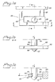
- a first embodiment of a locking arrangement according to the invention showing the general function of locking a member 104 to a main body 103, is illustrated in figures 1a, 1b and 1c.
- the arrangement comprises a lock and release unit 100 and a plunger 105.
- FIG. 1a A first side view is shown in figure 1a where the lock and release unit 100 is attached to the main body 103.
- the particular properties of the main body 103 are outside the scope of the invention, although a typical main body 103 may be a portable device such as a telephone as will be further exemplified below.
- the attachment of the lock and release device 100 to the main body 103 is also outside the scope of the invention and is hence not explained in further detail in connection with figures 1a-c.
- the lock and release device 100 comprises an elongated fixed part 101, which is attached to the main body 103, and an elongated resilient part 102.
- the resilient part 102 is resilient along a direction X away from the fixed part 101 creating a gap 120 having varying extent between the fixed and resilient parts 101,102.
- a delimiting line 109 has been indicated in the figure in order to illustrate roughly where the resilient part 102 and the fixed part 101 of the lock and release unit 100 transit into each other.
- the delimiting line 109 is not an illustration of where the two parts 101,102 attach to each other, thus implicating a necessity of two seaparate parts. Rather, the delimiting line 109 is simply an indication of the fact that the lock and release unit 100 may be in the form of one single unit as well as being formed of two separate parts joined together.
- the actual resilience of the resilient part 102 is obtained according to characteristics such as physical properties of the material of the part. It is known in the art how to obtain suitable resilient properties and it will hence not be discussed in detail. However, it is obvious that a injection molding is a reasonable choice. Nevertheless, other materials such as metals or even wood may be suitable depending on the application.
- an elongated plunger unit 105 having a notch 106 and a tapered end 107 is attached to the member 104.
- the member 104 is to be locked to the main body 103 by means of the locking arrangement comprising the plunger unit 105 and the lock and release unit 100. Examples of members 104 having specific characteristics will be discussed below in connection with other embodiments of the invention.
- the plunger unit 105 is in figures 1a-c located within the gap 120 between the resilient part 102 and the fixed part 101 locking the member 104 to the main body 103.
- the locking is effectuated by moving the plunger 105 with it's tapered end 107 along a direction Y, forcing the resilient part 102 along direction X, forcing the resilient part 102 along direction X widening the gap 120 until the notch 106 catches the resilient part 102 which retracts backwards against the direction X.
- the notch 106 comprises a slanted edge 108 along which the resilient part 102 slides when retracting.
- the direction X is mainly perpendicular to the direction y. This is also the case in the other following embodiments of the invention.
- the member 104 By forcing the member 104 with the attached plunger 105 backwards along the direction Y the member 104 may be unlocked from the main body 103.
- Such a backwards motion will entail the resilient part 102 sliding against the slanted edge 108 of the notch 106 and hence bring about a motion of the resilient part 102 towards the direction X, widening the gap 120 towards the direction X, widening 104 and plunger 105 will result in an unlocking of the plunger from the lock and release unit 100.
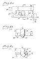
- a lock and release unit 200 comprising a fixed part 201 and a resilient part 202 is attached to a main body 203 of e.g. a portable device.
- the main body 203 may be a mobile telephone terminal. In such a case the main body 203 would correspond to a housing of such a telephone terminal.
- Both the fixed part 201 and the resilient part 202 are elongated and are forming a single unit.
- a dashed line 209 indicates roughly where a transition between the two parts 202, 202 is located.
- the resilient part 202 is resilient along a direction X away from the fixed part 201 creating a gap 220 having varying extent.
- Attached to, or rather forming an integrated part of, the resilient part 202 is an actuating part 212.
- the actuating part 212 extends through a hole 213 in the main body 203 making it accessible from without.
- an elongated plunger unit 205 having a notch 206 and a tapered end 207 is attached to a member 204.
- the member 204 is to be locked to the main body 203 by means of the locking arrangement comprising the plunger unit 205 and the lock and release unit 200.
- a typical example of a member 204 may be a flip-lid at a mobile telephone terminal.
- the plunger unit 205 is located within the gap 220 between the resilient part 202 and the fixed part 201 locking the member 204 to the main body 203.
- the locking and unlocking is effectuated by moving the plunger 205 along a direction Y, forcing the resilient part 202 along direction X widening the gap 220 until the notch 206 catches a slanted edge 211 of a notch 210 in the resilient part 201.
- the notch 206 in the plunger also comprises a slanted edge 208 along which the resilient part 202 slides when retracting.
- the member 204 with the attached plunger 205 is unlocked from the main body by a pulling force applied backwards along the direction Y.
- a backwards motion resulting from such a force will entail the slanted edge 211 of the notch 210 in the resilient part 202 sliding against the slanted edge 208 of the notch 206 and hence bring about a motion of the resilient part 202 towards the direction X, widening the gap 220.
- Further backward motion of the member 204 and plunger 205 will result in an unlocking of the plunger 205 from the lock and release unit 200.
- the pulling force needed to release the plunger 205 from the locked position depends of course on the sizes an physical characteristics of the parts involved.
- the unlocking action may be facilitated.
- a force may be applied via the actuating part 212.
- both the locking action and the unlocking action may be facilitated by way of applying a force upon the actuating part 212 along the direction X.
- FIG. 3 An embodiment according to the invention of a locking arrangement 300 is schematically disclosed in figure 3.
- a fixed part 301 is attached to a main body 303 such as a housing of a telephone terminal.
- the fixed part 301 transfer to a resilient part 302 at a location indicated by a dashed line 309.
- the resilient part 302 is resilient along a direction X and is capable of being dislocated forwards and backwards along the direction X via an actuating part 312.
- the actuating part 312 forms part of an end of an actuating arm 314 which is elongated along the direction X and attached to the resilient part 302.
- the actuating arm 314 extends through a hole 313 in the main body 303 in more or less the same manner as in the previous example.
- Figure 3 also shows a plunger 305 having a notch 306 which is capable of being engaged into a locked position and disengaged from the locked position as shown in the examples above.
- FIG. 4 Yet another example of a locking arrangement 400 is schematically disclosed in figure 4.
- a fixed part 401 is attached to a main body 403.
- the fixed part 401 transfer to a resilient part 402 which is resilient along a direction X.
- a plunger 405 In a gap 420 between the fixed part 401 and the resilient part 402 is a plunger 405 with a notch 406 located.
- This example is merely to illustrate yet a different shape of the parts, as e.g. the rectangular cross-section of the plunger 405 seen in the figure.
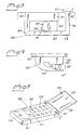
- a mobile telephone terminal 500 comprises a main body in the form of a housing 503 to which is attached a flip-lid 520. As is known in the art the terminal comprises means for communicating in a telecommunication network. In the housing 503 is located a display 524, keys 525 and a loudspeaker 523 and in the flip-lid 520 a microphone.
- the flip-lid 520 is capable of being rotated from an open position to a closed position covering the keys 525 around an axis R by means of a hinge mechanism 521.
- the hinge mechanism 521 may comprise means for spring-loading the lid 520 when in the closed position against the housing 503.
- the flip-lid 520 is in figure 5 shown in the open position.
- the terminal 500 comprises a locking arangement according to the present invention.
- a plunger unit 505 is attached to the flip-lid 520 and a lock and release unit (700 in figure 7a) is attached inside the housing 503.
- a hole 513 in the housing 503 allows access for the plunger 505 to the lock and release unit (700 in figure 7a).
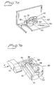
- Figures 6a-c show three side views of a plunger 605 such as the plunger 505 shown attached to the flip-lid 520 in figure 5.
- the plunger has a tapered end 607 and a notch 606 with a slanted edge 608, generally of the same shape as the plungers 105,205 shown in previous examples.
- the plunger 605 is shown to be a separate part detached from any flip-lid etc, it is understood that the plunger 605 may be an integral part of the flip-lid (520 in figure 5).
- Figures 7a and 7b show in some detail a lock and release unit 700 which is attached to the inside of a housing 703, corresponding to the housing 503 in figure 5.
- the resilient part 702 has a direction of resilience X away from the fixed part 701 which enables a gap 720 between the two parts to become wider when a force is applied along the direction X on the actuating part 712.
- the fixed part 701 is attached to the inside of the housing 703 by means of knobs 717 protruding from the housing 703 and engaging the fixed part 701 via an opening 716.
- a tip 707 of a plunger (505 in figure 5, 605 in figure 6a-c) having a tapered end 707 is engaged in a notch 708 in the resilient part 702 in the same manner as disclosed in previous examples above.
- the gap 720 widens and the plunger is detached from the engaged position.
Landscapes
- Engineering & Computer Science (AREA)
- Mechanical Engineering (AREA)
- Signal Processing (AREA)
- Telephone Set Structure (AREA)
- Snaps, Bayonet Connections, Set Pins, And Snap Rings (AREA)
- Piles And Underground Anchors (AREA)
- Lock And Its Accessories (AREA)
- Transmitters (AREA)
- Mobile Radio Communication Systems (AREA)
Applications Claiming Priority (3)
| Application Number | Priority Date | Filing Date | Title |
|---|---|---|---|
| SE9801221A SE511860C2 (sv) | 1998-04-07 | 1998-04-07 | Låsmekanism för mekanisk sammankoppling av två anordningar samt portabel kommunikationsanordning försedd med en dylik låsmekanism |
| SE9801221 | 1998-04-07 | ||
| PCT/SE1999/000560 WO1999051885A1 (en) | 1998-04-07 | 1999-04-06 | Arrangement relating to mechanically interlocking devices |
Publications (2)
| Publication Number | Publication Date |
|---|---|
| EP1070205A1 EP1070205A1 (en) | 2001-01-24 |
| EP1070205B1 true EP1070205B1 (en) | 2004-06-23 |
Family
ID=20410886
Family Applications (1)
| Application Number | Title | Priority Date | Filing Date |
|---|---|---|---|
| EP99921335A Expired - Lifetime EP1070205B1 (en) | 1998-04-07 | 1999-04-06 | Arrangement relating to mechanically interlocking devices |
Country Status (15)
| Country | Link |
|---|---|
| US (1) | US6363243B1 (enExample) |
| EP (1) | EP1070205B1 (enExample) |
| JP (1) | JP4391688B2 (enExample) |
| KR (1) | KR20010042460A (enExample) |
| CN (1) | CN1148515C (enExample) |
| AR (1) | AR015267A1 (enExample) |
| AU (1) | AU756891B2 (enExample) |
| BR (1) | BR9909466A (enExample) |
| CO (1) | CO5021174A1 (enExample) |
| DE (1) | DE69918282T2 (enExample) |
| EE (1) | EE04251B1 (enExample) |
| MY (1) | MY124326A (enExample) |
| SE (1) | SE511860C2 (enExample) |
| TR (1) | TR200002861T2 (enExample) |
| WO (1) | WO1999051885A1 (enExample) |
Families Citing this family (5)
| Publication number | Priority date | Publication date | Assignee | Title |
|---|---|---|---|---|
| JP2001251400A (ja) * | 2000-03-03 | 2001-09-14 | Matsushita Electric Ind Co Ltd | 携帯電話機 |
| US7003333B2 (en) * | 2002-09-17 | 2006-02-21 | Motorola, Inc. | Latch mechanism and electronic device employing a latch mechanism |
| JP4703982B2 (ja) * | 2004-07-15 | 2011-06-15 | パナソニック株式会社 | 携帯電子機器 |
| CN201123002Y (zh) * | 2007-07-11 | 2008-09-24 | 招家荣 | 一种便携式携带装置 |
| CN108915921B (zh) * | 2013-10-01 | 2021-01-15 | 恩普乐斯股份有限公司 | 燃料喷射装置用喷嘴板的安装构造 |
Family Cites Families (12)
| Publication number | Priority date | Publication date | Assignee | Title |
|---|---|---|---|---|
| JPS586070U (ja) * | 1981-07-03 | 1983-01-14 | 北川工業株式会社 | 電線クランプ |
| GB2106977B (en) * | 1981-09-10 | 1985-02-13 | Yoshida Industry Co | Vanity case |
| SE441261B (sv) * | 1984-03-26 | 1985-09-23 | Jan Ingemar Neslund | Pasklemma |
| JPH04281628A (ja) * | 1991-03-11 | 1992-10-07 | Matsushita Electric Ind Co Ltd | 携帯形無線機 |
| US5274882A (en) * | 1992-03-03 | 1994-01-04 | Ericsson Ge Mobile Communications Inc. | Hinge mechanism |
| JP2689913B2 (ja) * | 1994-07-15 | 1997-12-10 | 日本電気株式会社 | 自動開放型折畳み携帯無線機 |
| JP2658906B2 (ja) * | 1994-09-22 | 1997-09-30 | 日本電気株式会社 | 自動オープン式折り畳み携帯電話機 |
| FI99070C (fi) * | 1995-06-30 | 1997-09-25 | Nokia Mobile Phones Ltd | Teline |
| SE507149C2 (sv) * | 1996-08-29 | 1998-04-06 | Ericsson Telefon Ab L M | Gångjärnsanordning |
| US5956398A (en) * | 1997-07-11 | 1999-09-21 | Ericsson Inc. | Telephone switching mechanism |
| US6151486A (en) * | 1998-10-30 | 2000-11-21 | Ericsson Inc. | Magnetic latch and release device and radiotelephones incorporating same |
| KR100621606B1 (ko) * | 1998-12-03 | 2006-11-30 | 삼성전자주식회사 | 휴대형 컴퓨터_ |
-
1998
- 1998-04-07 SE SE9801221A patent/SE511860C2/sv not_active IP Right Cessation
-
1999
- 1999-04-06 AU AU38574/99A patent/AU756891B2/en not_active Expired
- 1999-04-06 TR TR2000/02861T patent/TR200002861T2/xx unknown
- 1999-04-06 DE DE69918282T patent/DE69918282T2/de not_active Expired - Lifetime
- 1999-04-06 BR BR9909466-5A patent/BR9909466A/pt not_active IP Right Cessation
- 1999-04-06 MY MYPI99001304A patent/MY124326A/en unknown
- 1999-04-06 EP EP99921335A patent/EP1070205B1/en not_active Expired - Lifetime
- 1999-04-06 EE EEP200000572A patent/EE04251B1/xx unknown
- 1999-04-06 KR KR1020007011072A patent/KR20010042460A/ko not_active Ceased
- 1999-04-06 WO PCT/SE1999/000560 patent/WO1999051885A1/en not_active Ceased
- 1999-04-06 CN CNB998048690A patent/CN1148515C/zh not_active Expired - Lifetime
- 1999-04-06 JP JP2000542581A patent/JP4391688B2/ja not_active Expired - Lifetime
- 1999-04-07 CO CO99020330A patent/CO5021174A1/es unknown
- 1999-04-07 AR ARP990101581A patent/AR015267A1/es active IP Right Grant
- 1999-04-07 US US09/287,971 patent/US6363243B1/en not_active Expired - Lifetime
Also Published As
| Publication number | Publication date |
|---|---|
| BR9909466A (pt) | 2000-12-19 |
| CN1148515C (zh) | 2004-05-05 |
| KR20010042460A (ko) | 2001-05-25 |
| MY124326A (en) | 2006-06-30 |
| CO5021174A1 (es) | 2001-03-27 |
| US6363243B1 (en) | 2002-03-26 |
| AU756891B2 (en) | 2003-01-23 |
| TR200002861T2 (tr) | 2001-01-22 |
| JP4391688B2 (ja) | 2009-12-24 |
| AU3857499A (en) | 1999-10-25 |
| JP2002510778A (ja) | 2002-04-09 |
| SE9801221L (sv) | 1999-10-08 |
| EP1070205A1 (en) | 2001-01-24 |
| AR015267A1 (es) | 2001-04-18 |
| SE9801221D0 (sv) | 1998-04-07 |
| SE511860C2 (sv) | 1999-12-06 |
| HK1035220A1 (en) | 2001-11-16 |
| WO1999051885A1 (en) | 1999-10-14 |
| CN1296553A (zh) | 2001-05-23 |
| DE69918282D1 (de) | 2004-07-29 |
| DE69918282T2 (de) | 2005-07-28 |
| EE04251B1 (et) | 2004-02-16 |
| EE200000572A (et) | 2002-04-15 |
Similar Documents
| Publication | Publication Date | Title |
|---|---|---|
| US5987122A (en) | Portable phone with cover actuating hinge assembly | |
| US6963756B2 (en) | Electronic equipment comprising a retractable screen | |
| KR100225161B1 (ko) | 표면접점부착 카드용 커넥터 | |
| JPH04281628A (ja) | 携帯形無線機 | |
| HU206171B (en) | Hinged construction to the folding radiotelephone | |
| CN1965560B (zh) | 包括带片簧的可滑动铰链的可折叠的电子设备 | |
| US7014045B2 (en) | Cosmetic compact | |
| US20070111086A1 (en) | Battery cover latching assembly for portable electronic device | |
| EP1070205B1 (en) | Arrangement relating to mechanically interlocking devices | |
| US6203077B1 (en) | Over-center toggle latch with integral safety switch | |
| JP2584137B2 (ja) | 携帯形無線機 | |
| US8958205B2 (en) | Cover opening/closing apparatus for portable communication device | |
| US20070064381A1 (en) | Foldable electronic device | |
| KR200395863Y1 (ko) | 푸쉬 푸쉬형 이동통신 단말기 | |
| US7072689B1 (en) | Lock and release mechanism for a wireless device | |
| HK1038051B (en) | Locking arrangement and portable communication device comprising the same | |
| HK1038051A (en) | Locking arrangement and portable communication device comprising the same | |
| JP3379808B2 (ja) | 蓋体用止め具 | |
| KR100389991B1 (ko) | 휴대형 절첩식 무선 통신 기기 | |
| KR100661570B1 (ko) | 휴대폰의 배터리 잠금장치 | |
| JPH0714062U (ja) | スイッチ付きロック及び解除装置 | |
| JP2001267002A (ja) | 扉の開閉構造 | |
| JP2579297Y2 (ja) | 分電函の蓋体係合構造 | |
| JPH0945170A (ja) | 操作ボタン装置 | |
| KR100689510B1 (ko) | 휴대용 단말기의 배터리 팩 락킹 장치 |
Legal Events
| Date | Code | Title | Description |
|---|---|---|---|
| PUAI | Public reference made under article 153(3) epc to a published international application that has entered the european phase |
Free format text: ORIGINAL CODE: 0009012 |
|
| 17P | Request for examination filed |
Effective date: 20000920 |
|
| AK | Designated contracting states |
Kind code of ref document: A1 Designated state(s): BE DE ES FI FR GB IT |
|
| 17Q | First examination report despatched |
Effective date: 20021115 |
|
| GRAP | Despatch of communication of intention to grant a patent |
Free format text: ORIGINAL CODE: EPIDOSNIGR1 |
|
| GRAS | Grant fee paid |
Free format text: ORIGINAL CODE: EPIDOSNIGR3 |
|
| RAP1 | Party data changed (applicant data changed or rights of an application transferred) |
Owner name: TELEFONAKTIEBOLAGET LM ERICSSON (PUBL) |
|
| GRAA | (expected) grant |
Free format text: ORIGINAL CODE: 0009210 |
|
| AK | Designated contracting states |
Kind code of ref document: B1 Designated state(s): BE DE ES FI FR GB IT |
|
| PG25 | Lapsed in a contracting state [announced via postgrant information from national office to epo] |
Ref country code: IT Free format text: LAPSE BECAUSE OF FAILURE TO SUBMIT A TRANSLATION OF THE DESCRIPTION OR TO PAY THE FEE WITHIN THE PRESCRIBED TIME-LIMIT;WARNING: LAPSES OF ITALIAN PATENTS WITH EFFECTIVE DATE BEFORE 2007 MAY HAVE OCCURRED AT ANY TIME BEFORE 2007. THE CORRECT EFFECTIVE DATE MAY BE DIFFERENT FROM THE ONE RECORDED. Effective date: 20040623 Ref country code: FR Free format text: LAPSE BECAUSE OF FAILURE TO SUBMIT A TRANSLATION OF THE DESCRIPTION OR TO PAY THE FEE WITHIN THE PRESCRIBED TIME-LIMIT Effective date: 20040623 Ref country code: FI Free format text: LAPSE BECAUSE OF FAILURE TO SUBMIT A TRANSLATION OF THE DESCRIPTION OR TO PAY THE FEE WITHIN THE PRESCRIBED TIME-LIMIT Effective date: 20040623 Ref country code: ES Free format text: LAPSE BECAUSE OF FAILURE TO SUBMIT A TRANSLATION OF THE DESCRIPTION OR TO PAY THE FEE WITHIN THE PRESCRIBED TIME-LIMIT Effective date: 20040623 Ref country code: BE Free format text: LAPSE BECAUSE OF FAILURE TO SUBMIT A TRANSLATION OF THE DESCRIPTION OR TO PAY THE FEE WITHIN THE PRESCRIBED TIME-LIMIT Effective date: 20040623 |
|
| REG | Reference to a national code |
Ref country code: GB Ref legal event code: FG4D |
|
| REF | Corresponds to: |
Ref document number: 69918282 Country of ref document: DE Date of ref document: 20040729 Kind code of ref document: P |
|
| PGFP | Annual fee paid to national office [announced via postgrant information from national office to epo] |
Ref country code: GB Payment date: 20050330 Year of fee payment: 7 |
|
| PLBE | No opposition filed within time limit |
Free format text: ORIGINAL CODE: 0009261 |
|
| STAA | Information on the status of an ep patent application or granted ep patent |
Free format text: STATUS: NO OPPOSITION FILED WITHIN TIME LIMIT |
|
| 26N | No opposition filed |
Effective date: 20050324 |
|
| EN | Fr: translation not filed | ||
| PG25 | Lapsed in a contracting state [announced via postgrant information from national office to epo] |
Ref country code: GB Free format text: LAPSE BECAUSE OF NON-PAYMENT OF DUE FEES Effective date: 20060406 |
|
| GBPC | Gb: european patent ceased through non-payment of renewal fee |
Effective date: 20060406 |
|
| PGFP | Annual fee paid to national office [announced via postgrant information from national office to epo] |
Ref country code: DE Payment date: 20180427 Year of fee payment: 20 |
|
| REG | Reference to a national code |
Ref country code: DE Ref legal event code: R071 Ref document number: 69918282 Country of ref document: DE |