EP1069449A2 - Système d'illumination d'un microscope pour l'ultraviolet profond - Google Patents
Système d'illumination d'un microscope pour l'ultraviolet profond Download PDFInfo
- Publication number
- EP1069449A2 EP1069449A2 EP00111442A EP00111442A EP1069449A2 EP 1069449 A2 EP1069449 A2 EP 1069449A2 EP 00111442 A EP00111442 A EP 00111442A EP 00111442 A EP00111442 A EP 00111442A EP 1069449 A2 EP1069449 A2 EP 1069449A2
- Authority
- EP
- European Patent Office
- Prior art keywords
- duv
- reflection
- beam path
- vis
- lighting device
- Prior art date
- Legal status (The legal status is an assumption and is not a legal conclusion. Google has not performed a legal analysis and makes no representation as to the accuracy of the status listed.)
- Granted
Links
- 238000005286 illumination Methods 0.000 title claims abstract description 33
- 230000003595 spectral effect Effects 0.000 claims description 12
- 230000003287 optical effect Effects 0.000 claims description 6
- 229910004298 SiO 2 Inorganic materials 0.000 claims description 3
- 229910018072 Al 2 O 3 Inorganic materials 0.000 claims description 2
- 239000000758 substrate Substances 0.000 claims 1
- 239000012780 transparent material Substances 0.000 claims 1
- 230000001419 dependent effect Effects 0.000 description 7
- 230000010287 polarization Effects 0.000 description 7
- 230000005540 biological transmission Effects 0.000 description 5
- 230000000694 effects Effects 0.000 description 3
- 239000011521 glass Substances 0.000 description 3
- 239000000463 material Substances 0.000 description 3
- 238000001228 spectrum Methods 0.000 description 2
- 238000007740 vapor deposition Methods 0.000 description 2
- VYPSYNLAJGMNEJ-UHFFFAOYSA-N Silicium dioxide Chemical compound O=[Si]=O VYPSYNLAJGMNEJ-UHFFFAOYSA-N 0.000 description 1
- 239000012876 carrier material Substances 0.000 description 1
- 230000003760 hair shine Effects 0.000 description 1
- 229910052736 halogen Inorganic materials 0.000 description 1
- 150000002367 halogens Chemical class 0.000 description 1
- 238000003384 imaging method Methods 0.000 description 1
- 238000007689 inspection Methods 0.000 description 1
- 239000002184 metal Substances 0.000 description 1
- 238000000034 method Methods 0.000 description 1
- 238000001000 micrograph Methods 0.000 description 1
- 210000001747 pupil Anatomy 0.000 description 1
Images


Classifications
-
- G—PHYSICS
- G02—OPTICS
- G02B—OPTICAL ELEMENTS, SYSTEMS OR APPARATUS
- G02B21/00—Microscopes
- G02B21/16—Microscopes adapted for ultraviolet illumination ; Fluorescence microscopes
Definitions
- the invention relates to an illumination device for a DUV microscope the features of the preamble of independent claim 1.
- the DUV wavelength band is characterized by the spectral peak position and the half-width of its peak.
- Both transmission narrow-band filter systems and reflection filter systems are known for generating such a DUV wavelength band. These filter systems are inserted into the illumination beam path and filter a desired DUV wavelength band as useful light from the light spectrum of a light source.
- the microscope image is made visible with a DUV-sensitive TV camera.
- Transmission narrow-band filter systems in the DUV deliver very narrow peaks, the maximum transmission and therefore the peak value of the peak is included only about 20 percent of the light intensity in front of the transmission narrow-band filter system.
- Such weak intensities require particularly sensitive ones and therefore technologically complex and very expensive cameras.
- the significant disadvantage of these cameras e.g. with so-called "frame transfer CCD imagers" is, however, that they have very long exposure and image readout times have, so that a "life" observation of the object is impossible. This is particularly annoying when the stage moves with the object on it must become.
- the invention is based on the consideration that the large half-widths essentially through polarization effects on the reflection filter systems caused. These are significantly lower for smaller reflection angles.
- a reflection filter system is therefore used in a DUV lighting device according to the invention with small reflection angles and spectrally adjusted Reflection filters used.
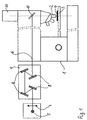
- a lighting device for a DUV microscope has a light source from which an illumination beam path emanates.
- Illumination beam paths are a collector and a reflection filter system arranged to generate a desired DUV wavelength band.
- the Reflection filter system consists of four reflection filters on which the illuminating beam path is reflected at the same angle of reflection a.
- the illuminating beam path runs in front of and behind the reflection filter system coaxial. According to the angle of reflection a at the individual reflection filters between ⁇ ⁇ 30 °.
- the reflection filter system provides a very narrow DUV wavelength band ⁇ DUV + ⁇ with a half width of max. 20 nm. It has a peak with a peak value S of over 90% of the incident light intensity. Depending on the reflection filter used, a peak peak value S of over 98% of the incident light intensity can be achieved with a reflection filter system with small angles of incidence.
- reflection filters specially matched to the desired DUV wavelength band ⁇ DUV + ⁇ are used in the reflection filter system of the lighting device according to the invention.
- the reflection filter system can the polarization effects on the reflection filters reduced and narrow half-widths can be achieved. For half-widths in the order of magnitude achieved, it is possible to correct appropriately Calculate DUV microscope objectives. At the same time has a DUV microscope sufficient with a lighting device according to the invention high intensities in the illumination beam path in order to focus on complex special DUV-sensitive cameras, such as the frame transfer CCD cameras mentioned, with slow image build-up.
- An illuminating beam path 6 emanates from the light source 5, passes through a collector 7 and a reflecting filter system 9 constructed from four reflecting filters 8. From there, the illuminating beam path 6 passes through an optical system (not shown), is deflected at a beam splitter 10 and through the objective 2 onto the Object 4 focused.
- the imaging beam path emanating from the object 4 passes through the objective 2 and the beam splitter 10 to the TV camera 11.
- the reflection filters 8 in the reflection filter system 9 are like this arranged that the illumination beam path 6 on all reflection filters 8th with the same small angle of incidence ⁇ .
- An angle of 30 ° is shown here. Smaller angles are possible according to the invention.
- reflection filter filter systems with angles of incidence ⁇ ⁇ 15 ° due to the narrow geometry can only be realized with difficulty.
- the desired DUV wavelength range adapted reflection filter 8 from vapor deposition layers are applied to black glass.
- the desired DUV portion of the lamp light is reflected.
- the parts passing through the vapor deposition layers of the lamp light, i.e. the remaining DUV portion as well as the UV and VIS components are absorbed in the black glass. In this way it is created Illumination with only the desired DUV wavelength range.
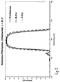
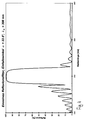
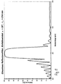
- the polarization components with vertical (“S-Pol”) and parallel (“P-Pol”) polarization directions are shown. These two curves are very close together because the polarization effect is only very small due to the small angle of incidence. Therefore, the summation curve "pole-sum" from the two polarization directions also has only a very small half-width ⁇ with a value of approximately 20 nm. This means that the DUV wavelength band ⁇ DUV generated with a reflection filter system with a small angle of incidence is sufficiently narrow to be able to correct the DUV optics of the microscope.
- the reflection filters have a layer structure as shown in Table 1. Only the thicknesses of the layers are corrected in accordance with the desired angle of incidence ci by a reference wavelength ⁇ 0 , which is included in the calculation of the layer thicknesses. The associated reference wavelengths ⁇ 0 are given in the figures. By adapting the layer thicknesses, the reflection filters have the same qualitative reflection behavior for different angles of incidence. 6 shows the reference wavelength ⁇ 0 as a function of the angle of incidence ⁇ . It can be seen that for changes to larger angles of incidence, the reference wavelength ⁇ 0 must be corrected significantly more.
- the layer system from Table 1 is again suitable, for example. However, it is also possible to design other layer systems, for example using SiO 2 and AlO 3 . It is important to use materials with the smallest possible differences in their refractive indices. With the layer system from Table 1, at least for a DUV wavelength between 180 and 300 nm, a reflection filter system that is suitable for a narrow DUV wavelength band can be specified.
- Fig. 8 shows a switchable lighting device for optional VIS or DUV lighting, which is equipped with two separate light sources for two wavelength ranges.
- the structure corresponds in principle to FIG. 1.
- the same components have the same reference numerals.
- An additional VIS light source 12 for the visible spectral range has been added to the previously described lighting device from FIG. 1 with the DUV light source 5.
- This VIS light source 12 is, for example, an Hg incandescent lamp which only emits spectral components in the VIS wavelength range, but not in the UV and DUV wavelength ranges.
- the light from this VIS light source 12 passes through a collector 13 and is only coupled vertically into the illuminating beam path 6 when an additionally installed, pivotable mirror 14 is located in the illuminating beam path 6 in the position "b". Then the VIS light arrives at the object 4 on the following part of the illumination beam path 6.
- the swivel mirror 14 is brought into the position "a”. Then the light from the DUV light source 5 reaches the object 4 as in FIG. 1 .
- the structure described requires a second light source, but is through the swivel mirror 14 easy to implement.
- the structure also expands the possibilities of using the microscope considerably. This is how the DUV light source shines 5, e.g. an Hg arc lamp, also in the UV and VIS wavelength range from. However, it has only a small arc, the with weaker VIS lenses, the pupil cannot fill and therefore no lighting for these lenses. In addition, the DUV light source 5 not dimmable.
- the VIS light source e.g. a halogen light bulb, one sufficiently large filament for sufficient lighting also with weaker VIS lenses and is dimmable. You have UV or DUV portions Spectrum not on. Therefore, with the structure described, a DUV microscope be equipped with all the options for a VIS inspection.
- FIG. 9 shows the different positions of the images of a universal light source for the VIS and UV and DUV wavelength ranges in a DUV lighting device.
- the light from the light source 15 passes through a collector 16 and a reflection filter system 9, which is constructed from four reflection filters 8.
- the reflection filters 8 are evaporated on black glass.
- the different positions of the image 17 of the light source 15 for the DUV wavelength 248 nm, the so-called "i-line” 365 nm and the visible VIS wavelength range are shown schematically.
- the light source 15 would have to be different spectral lighting method in the direction of the illumination beam path 6 be moved.
- FIGS. 10-11 An alternative to this is shown in FIGS. 10-11 .
- a switchable lighting device for either VIS or DUV lighting is shown, which works with only one universal DUV-VIS light source.
- the DUV light source 5 is used, which is an Hg arc lamp, for example.
- An illuminating beam path 6 starts from the DUV light source 5, in which a collector 7 and a reflection filter system 9 with four reflection filters 8 are arranged.
- the four reflection filters 8 are individually identified here with 8a, 8b, 8c and 8d to differentiate their spatial position.
- the reflection filters 8a, 8b, 8c and 8d are vapor-deposited on a carrier material, ie quartz glass, which is transparent for all wavelength ranges.
- a light stopper 18 is inserted between the reflection filter 8a and the reflection filter 8d.
- This can be any opaque plate, e.g. made of metal. This stops the portion of the lamp light passing through the reflection filter 8a, so that only the reflected DUV wavelength band is used for illumination.
- the position 17 of the image of the light source 5 is indicated.
- the lenses 19 shift the position 17 of the VIS image of the light source to the position of the DUV image of the light source.
- the filter 20 can be a color filter or gray filter etc.
- a light stopper 18 is inserted between the reflection filter 8b and the reflection filter 8d in order to exclude any DUV component from the illumination during the VIS illumination.
- FIG. 12 shows a linear slide 21 with which the two switching stages from FIGS. 10 and 11 and one further switching stage can be implemented.
- the linear slide 21 shows three buttons 22, 23, 24 for different spectral lighting variants.
- the linear slide 21 is inserted vertically into the illumination beam path 6 in the reflection filter system 9, so that its upper half is always between the reflection filter 8b and the reflection filter 8c and its lower half is always between the reflection filter 8a and the reflection filter 8d.
- Only one of the buttons 22, 23, 24 is optionally inserted into the illumination beam path 6.
- the position 28 of the reflection filter system is represented by a dashed frame. In FIG. 12 , the button 23 is therefore currently inserted in the reflection filter system.
- the button 22 generates a DUV lighting, thus corresponds to FIG. 10 .
- a free opening 25 is arranged in its upper half to allow the DUV light to pass through.
- a light stopper 18 is arranged in its lower half.
- the button 23 generates a VIS illumination, which corresponds to FIG. 11 .
- a light stopper 18 is arranged in its upper half to stop the DUV light.
- a lens-filter combination 26 of lenses and at least one filter is inserted in its lower half, which are selected for the VIS range.
- the lenses correct the position of the image of the light source.
- the filters can be selected as required, eg color filters, gray filters, fluorescence filters etc.
- a further lighting with wavelengths outside of the DUV wavelength band can be set.
- a light stopper 18 is again arranged to stop the DUV light.
- any lens-filter combination 27 is inserted into its lower half, which is selected for example for the so-called "i-line" at 365 nm.
Landscapes
- Physics & Mathematics (AREA)
- Chemical & Material Sciences (AREA)
- Analytical Chemistry (AREA)
- General Physics & Mathematics (AREA)
- Optics & Photonics (AREA)
- Microscoopes, Condenser (AREA)
- Optical Filters (AREA)
Applications Claiming Priority (2)
| Application Number | Priority Date | Filing Date | Title |
|---|---|---|---|
| DE19931954A DE19931954A1 (de) | 1999-07-10 | 1999-07-10 | Beleuchtungseinrichtung für ein DUV-Mikroskop |
| DE19931954 | 1999-07-10 |
Publications (4)
| Publication Number | Publication Date |
|---|---|
| EP1069449A2 true EP1069449A2 (fr) | 2001-01-17 |
| EP1069449A3 EP1069449A3 (fr) | 2004-01-28 |
| EP1069449B1 EP1069449B1 (fr) | 2005-11-30 |
| EP1069449B8 EP1069449B8 (fr) | 2006-02-01 |
Family
ID=7914158
Family Applications (1)
| Application Number | Title | Priority Date | Filing Date |
|---|---|---|---|
| EP00111442A Expired - Lifetime EP1069449B8 (fr) | 1999-07-10 | 2000-05-27 | Système d'illumination d'un microscope pour l'ultraviolet profond |
Country Status (5)
| Country | Link |
|---|---|
| US (1) | US6624930B1 (fr) |
| EP (1) | EP1069449B8 (fr) |
| JP (2) | JP3600783B2 (fr) |
| DE (2) | DE19931954A1 (fr) |
| TW (1) | TW448308B (fr) |
Cited By (3)
| Publication number | Priority date | Publication date | Assignee | Title |
|---|---|---|---|---|
| WO2002086579A1 (fr) * | 2001-04-23 | 2002-10-31 | Leica Microsystems Semiconductor Gmbh | Microscope de controle pour plusieurs gammes de longueurs d'onde et couche antireflet destinee a un microscope de controle pour plusieurs gammes de longueurs d'onde |
| DE10137964A1 (de) * | 2001-08-08 | 2003-03-06 | Leica Microsystems | Mikroskop mit umschaltbarer Beleuchtung in mindestens zwei Spektralbereichen und Vorrichtung zur Beleuchtungsumschaltung |
| WO2002086580A3 (fr) * | 2001-04-23 | 2003-05-01 | Leica Microsystems | Dispositif d'eclairage |
Families Citing this family (13)
| Publication number | Priority date | Publication date | Assignee | Title |
|---|---|---|---|---|
| DE10311286A1 (de) | 2003-03-14 | 2004-09-23 | Leica Microsystems Semiconductor Gmbh | Beleuchtungsvorrichtung für ein optisches System |
| DE10329406B4 (de) * | 2003-06-26 | 2009-04-02 | Carl Zeiss Jena Gmbh | Transmissions-Filtereinrichtung |
| DE10332062A1 (de) * | 2003-07-11 | 2005-01-27 | Carl Zeiss Jena Gmbh | Anordnung im Beleuchtungsstrahlengang eines Laser-Scanning-Mikroskopes |
| JP2007058130A (ja) * | 2005-08-26 | 2007-03-08 | Japan Science & Technology Agency | 極端紫外線顕微鏡及び検査方法 |
| US7787112B2 (en) * | 2007-10-22 | 2010-08-31 | Visiongate, Inc. | Depth of field extension for optical tomography |
| US8143600B2 (en) | 2008-02-18 | 2012-03-27 | Visiongate, Inc. | 3D imaging of live cells with ultraviolet radiation |
| US8254023B2 (en) * | 2009-02-23 | 2012-08-28 | Visiongate, Inc. | Optical tomography system with high-speed scanner |
| US10048480B2 (en) | 2011-01-07 | 2018-08-14 | Zeta Instruments, Inc. | 3D microscope including insertable components to provide multiple imaging and measurement capabilities |
| WO2013015734A1 (fr) * | 2011-07-24 | 2013-01-31 | Applied Presicion, Inc. | Microscopes à fluorescence avec changeurs de miroirs polychroïques |
| US11069054B2 (en) | 2015-12-30 | 2021-07-20 | Visiongate, Inc. | System and method for automated detection and monitoring of dysplasia and administration of immunotherapy and chemotherapy |
| JP2018146765A (ja) * | 2017-03-06 | 2018-09-20 | 河合光学株式会社 | 光学フィルターの形成方法 |
| CN108387961A (zh) * | 2018-05-16 | 2018-08-10 | 德州尧鼎光电科技有限公司 | 一种深紫外窄带滤光片 |
| JP7381085B2 (ja) * | 2018-12-25 | 2023-11-15 | 英弘精機株式会社 | 気象観測ライダー用受光系 |
Family Cites Families (9)
| Publication number | Priority date | Publication date | Assignee | Title |
|---|---|---|---|---|
| DE2010540A1 (de) * | 1969-03-12 | 1970-12-17 | Olympus Optical Co. Ltd., Tokio | PR 12.03.69 Japan 21559-69 Fluoreszenzmikroskop |
| US3798435A (en) * | 1973-08-09 | 1974-03-19 | Reichert Optische Werke Ag | Versatile light source for a microscope |
| US4669811A (en) * | 1983-11-17 | 1987-06-02 | Pilkington P.E. Limited | Optical filtering apparatus |
| DE3902144A1 (de) * | 1989-01-25 | 1990-08-02 | Heraeus Gmbh W C | Deuterium-lampe fuer spektralanalyse-vorrichtungen |
| US5022726A (en) * | 1989-12-20 | 1991-06-11 | Viratec Thin Films, Inc. | Magnesium film reflectors |
| US5182670A (en) * | 1991-08-30 | 1993-01-26 | Apa Optics, Inc. | Narrow band algan filter |
| JPH0758355A (ja) * | 1993-05-12 | 1995-03-03 | Optical Coating Lab Inc | Uv/ir反射太陽電池カバー |
| JPH08313728A (ja) * | 1995-05-16 | 1996-11-29 | Nikon Corp | 帯域フィルター |
| US5867329A (en) * | 1996-05-31 | 1999-02-02 | The United States Of America As Represented By The Secretary Of The Navy | Multiple-pass reflection filter |
-
1999
- 1999-07-10 DE DE19931954A patent/DE19931954A1/de not_active Withdrawn
-
2000
- 2000-05-27 DE DE50011735T patent/DE50011735D1/de not_active Expired - Lifetime
- 2000-05-27 EP EP00111442A patent/EP1069449B8/fr not_active Expired - Lifetime
- 2000-06-08 US US09/589,088 patent/US6624930B1/en not_active Expired - Lifetime
- 2000-07-05 TW TW089113334A patent/TW448308B/zh not_active IP Right Cessation
- 2000-07-10 JP JP2000208838A patent/JP3600783B2/ja not_active Expired - Lifetime
-
2004
- 2004-06-07 JP JP2004168501A patent/JP2004295145A/ja not_active Withdrawn
Cited By (6)
| Publication number | Priority date | Publication date | Assignee | Title |
|---|---|---|---|---|
| WO2002086579A1 (fr) * | 2001-04-23 | 2002-10-31 | Leica Microsystems Semiconductor Gmbh | Microscope de controle pour plusieurs gammes de longueurs d'onde et couche antireflet destinee a un microscope de controle pour plusieurs gammes de longueurs d'onde |
| WO2002086580A3 (fr) * | 2001-04-23 | 2003-05-01 | Leica Microsystems | Dispositif d'eclairage |
| US7268940B2 (en) | 2001-04-23 | 2007-09-11 | Vistec Semiconductor Systems Gmbh | Illuminating device |
| US7274505B2 (en) | 2001-04-23 | 2007-09-25 | Leica Microsystems Cms Gmbh | Inspection microscope for several wavelength ranges and reflection reducing layer for an inspection microscope for several wavelength ranges |
| DE10137964A1 (de) * | 2001-08-08 | 2003-03-06 | Leica Microsystems | Mikroskop mit umschaltbarer Beleuchtung in mindestens zwei Spektralbereichen und Vorrichtung zur Beleuchtungsumschaltung |
| DE10137964B4 (de) * | 2001-08-08 | 2004-04-08 | Leica Microsystems Wetzlar Gmbh | Mikroskop mit umschaltbarer Beleuchtung in mindestens zwei Spektralbereichen und Vorrichtung zur Beleuchtungsumschaltung |
Also Published As
| Publication number | Publication date |
|---|---|
| JP3600783B2 (ja) | 2004-12-15 |
| EP1069449A3 (fr) | 2004-01-28 |
| EP1069449B8 (fr) | 2006-02-01 |
| JP2004295145A (ja) | 2004-10-21 |
| TW448308B (en) | 2001-08-01 |
| JP2001042226A (ja) | 2001-02-16 |
| DE50011735D1 (de) | 2006-01-05 |
| US6624930B1 (en) | 2003-09-23 |
| DE19931954A1 (de) | 2001-01-11 |
| EP1069449B1 (fr) | 2005-11-30 |
Similar Documents
| Publication | Publication Date | Title |
|---|---|---|
| EP1356476B1 (fr) | Filtre spectral a bande etroite et son utilisation | |
| DE60312871T2 (de) | Gitter basierter spektraler filter zur unterdrückung von strahlung ausserhalb des nutzbandes in einem extrem-ultraviolett lithographiesystem | |
| EP1069449B1 (fr) | Système d'illumination d'un microscope pour l'ultraviolet profond | |
| DE69326630T2 (de) | Beleuchtungsvorrichtung für einen Projektionsbelichtungsapparat | |
| DE3913228C2 (de) | Spektroskopiesystem diffuser Reflexion und Verfahren zum Erhalten eines diffusen Reflexionsspektrums | |
| DE19520187C1 (de) | Optik zum Herstellen einer scharfen Beleuchtungslinie aus einem Laserstrahl | |
| EP1260835B1 (fr) | Filtre pour l'atténuation de rayons ultraviolets | |
| EP1664888B1 (fr) | Microscope a balayage avec eclairage evanescent | |
| DE3343145A1 (de) | Beobachtungsgeraet | |
| DE102020209889A1 (de) | Mikroskop und Verfahren zur mikroskopischen Bildaufnahme mit variabler Beleuchtung | |
| WO2012113603A1 (fr) | Dispositif d'éclairage | |
| DE2654505A1 (de) | Augenhintergrundkamera ohne unerwuenschtes reflexions- und diffusionslicht | |
| DE102009045135A1 (de) | Beleuchtungsoptik für die Mikrolithographie | |
| EP1093001A2 (fr) | Microscope confocal de balayage à laser | |
| DE4331570C2 (de) | Verfahren zum optischen Anregen einer Probe | |
| DE10215162A1 (de) | Strahlteilervorrichtung bzw. Laserrastermikroskop | |
| DE10021379A1 (de) | Optische Messanordnung insbesondere zur Schichtdickenmessung | |
| DE10300157B4 (de) | Konfokales 4-Pi-Mikroskop und Verfahren zur konfokalen 4-Pi-Mikroskopie | |
| EP1381902A2 (fr) | System a filtres reflechissants dans un dispositif d'eclairage | |
| DE10033142C2 (de) | Erregerfilter für ein Endoskop zur Fluoreszenzuntersuchung | |
| EP1381901A1 (fr) | Microscope de controle pour plusieurs gammes de longueurs d'onde et couche antireflet destinee a un microscope de controle pour plusieurs gammes de longueurs d'onde | |
| DE10109242C1 (de) | Schmalbandiger Spektralfilter und seine Verwendung | |
| DE4128506A1 (de) | Verfahren zum betreiben eines spektrometers | |
| DE102011004819A1 (de) | Mikroskop mit multispektraler Objektbeleuchtung | |
| DE10019428C1 (de) | Beleuchtung für eine Prüfvorrichtung |
Legal Events
| Date | Code | Title | Description |
|---|---|---|---|
| PUAI | Public reference made under article 153(3) epc to a published international application that has entered the european phase |
Free format text: ORIGINAL CODE: 0009012 |
|
| AK | Designated contracting states |
Kind code of ref document: A2 Designated state(s): AT BE CH CY DE DK ES FI FR GB GR IE IT LI LU MC NL PT SE |
|
| AX | Request for extension of the european patent |
Free format text: AL;LT;LV;MK;RO;SI |
|
| PUAL | Search report despatched |
Free format text: ORIGINAL CODE: 0009013 |
|
| AK | Designated contracting states |
Kind code of ref document: A3 Designated state(s): AT BE CH CY DE DK ES FI FR GB GR IE IT LI LU MC NL PT SE |
|
| AX | Request for extension of the european patent |
Extension state: AL LT LV MK RO SI |
|
| 17P | Request for examination filed |
Effective date: 20040603 |
|
| AKX | Designation fees paid |
Designated state(s): DE FR GB |
|
| RAP1 | Party data changed (applicant data changed or rights of an application transferred) |
Owner name: LEICA MICROSYSTEMS SEMICONDUCTOR GMBH |
|
| GRAP | Despatch of communication of intention to grant a patent |
Free format text: ORIGINAL CODE: EPIDOSNIGR1 |
|
| GRAS | Grant fee paid |
Free format text: ORIGINAL CODE: EPIDOSNIGR3 |
|
| GRAA | (expected) grant |
Free format text: ORIGINAL CODE: 0009210 |
|
| AK | Designated contracting states |
Kind code of ref document: B1 Designated state(s): DE FR GB |
|
| REG | Reference to a national code |
Ref country code: GB Ref legal event code: FG4D Free format text: NOT ENGLISH |
|
| RAP2 | Party data changed (patent owner data changed or rights of a patent transferred) |
Owner name: LEICA MICROSYSTEMS CMS GMBH |
|
| REF | Corresponds to: |
Ref document number: 50011735 Country of ref document: DE Date of ref document: 20060105 Kind code of ref document: P |
|
| GBT | Gb: translation of ep patent filed (gb section 77(6)(a)/1977) |
Effective date: 20060213 |
|
| PLBE | No opposition filed within time limit |
Free format text: ORIGINAL CODE: 0009261 |
|
| STAA | Information on the status of an ep patent application or granted ep patent |
Free format text: STATUS: NO OPPOSITION FILED WITHIN TIME LIMIT |
|
| 26N | No opposition filed |
Effective date: 20060831 |
|
| EN | Fr: translation not filed | ||
| PG25 | Lapsed in a contracting state [announced via postgrant information from national office to epo] |
Ref country code: FR Free format text: LAPSE BECAUSE OF FAILURE TO SUBMIT A TRANSLATION OF THE DESCRIPTION OR TO PAY THE FEE WITHIN THE PRESCRIBED TIME-LIMIT Effective date: 20070119 |
|
| PG25 | Lapsed in a contracting state [announced via postgrant information from national office to epo] |
Ref country code: FR Free format text: LAPSE BECAUSE OF FAILURE TO SUBMIT A TRANSLATION OF THE DESCRIPTION OR TO PAY THE FEE WITHIN THE PRESCRIBED TIME-LIMIT Effective date: 20051130 |
|
| PGFP | Annual fee paid to national office [announced via postgrant information from national office to epo] |
Ref country code: GB Payment date: 20190529 Year of fee payment: 20 Ref country code: DE Payment date: 20190731 Year of fee payment: 20 |
|
| REG | Reference to a national code |
Ref country code: GB Ref legal event code: PE20 Expiry date: 20200526 |
|
| PG25 | Lapsed in a contracting state [announced via postgrant information from national office to epo] |
Ref country code: GB Free format text: LAPSE BECAUSE OF EXPIRATION OF PROTECTION Effective date: 20200526 |