EP1069402A2 - Vorrichtung zur Positionsbestimmung von Reifen und Einstellvorrichtung zum Radausrichten - Google Patents
Vorrichtung zur Positionsbestimmung von Reifen und Einstellvorrichtung zum Radausrichten Download PDFInfo
- Publication number
- EP1069402A2 EP1069402A2 EP00305980A EP00305980A EP1069402A2 EP 1069402 A2 EP1069402 A2 EP 1069402A2 EP 00305980 A EP00305980 A EP 00305980A EP 00305980 A EP00305980 A EP 00305980A EP 1069402 A2 EP1069402 A2 EP 1069402A2
- Authority
- EP
- European Patent Office
- Prior art keywords
- wheel
- wire
- case
- arrow
- measuring device
- Prior art date
- Legal status (The legal status is an assumption and is not a legal conclusion. Google has not performed a legal analysis and makes no representation as to the accuracy of the status listed.)
- Withdrawn
Links
Images


Classifications
-
- G—PHYSICS
- G01—MEASURING; TESTING
- G01M—TESTING STATIC OR DYNAMIC BALANCE OF MACHINES OR STRUCTURES; TESTING OF STRUCTURES OR APPARATUS, NOT OTHERWISE PROVIDED FOR
- G01M17/00—Testing of vehicles
- G01M17/007—Wheeled or endless-tracked vehicles
- G01M17/0072—Wheeled or endless-tracked vehicles the wheels of the vehicle co-operating with rotatable rolls
-
- G—PHYSICS
- G01—MEASURING; TESTING
- G01B—MEASURING LENGTH, THICKNESS OR SIMILAR LINEAR DIMENSIONS; MEASURING ANGLES; MEASURING AREAS; MEASURING IRREGULARITIES OF SURFACES OR CONTOURS
- G01B5/00—Measuring arrangements characterised by the use of mechanical techniques
- G01B5/24—Measuring arrangements characterised by the use of mechanical techniques for measuring angles or tapers; for testing the alignment of axes
- G01B5/255—Measuring arrangements characterised by the use of mechanical techniques for measuring angles or tapers; for testing the alignment of axes for testing wheel alignment
-
- G—PHYSICS
- G01—MEASURING; TESTING
- G01B—MEASURING LENGTH, THICKNESS OR SIMILAR LINEAR DIMENSIONS; MEASURING ANGLES; MEASURING AREAS; MEASURING IRREGULARITIES OF SURFACES OR CONTOURS
- G01B2210/00—Aspects not specifically covered by any group under G01B, e.g. of wheel alignment, caliper-like sensors
- G01B2210/10—Wheel alignment
- G01B2210/28—Beam projector and related sensors, camera, inclinometer or other active sensing or projecting device
Definitions
- the present invention relates to a tire position detecting device for detecting the position of a tire, and to a wheel alignment adjusting device for adjustment the alignment of wheels of a vehicle.
- wheels of a vehicle are provided with a camber angle for ensuring traveling stability of the vehicle, and are provided with a toe angle for preventing irregular wear caused by the provision of the camber angle.
- a toe angle is provided in order to balance the forces generated at the front tires and at the rear tires of the vehicle so as to ensure travelling stability of the vehicle, and the toe angle and the camber angle are combined so as to carry out adjustment for improving the traveling stability of the vehicle and minimizing the irregular wear of the tire under limiting conditions such as the structural dimensions of the vehicle and the like.
- the toe angle and the camber angle which are positional angles (wheel angles) applied to each wheel.
- Adjustment of the toe angle and the camber angle is carried out by using a wheel alignment adjusting device.
- wheel alignment adjustment of a vehicle When wheel alignment adjustment of a vehicle is to be carried out at a wheel alignment adjusting device, the vehicle is loaded onto the wheel alignment adjusting device from one end of the device, and is stopped at a predetermined position. The wheels are fixed, various measurements are carried out, and wheel alignment adjustment is carried out on the basis of the various measured values.
- the center line of the wheel alignment adjusting device and the center line of the vehicle body must correspond with one another.
- the positions of the respective wheels have been measured by using a laser (e.g., Japanese Patent Application Laid-Open (JP-A) No. 9-280843, JP-A-9-329433), or by a potentiometer (JP-A-7-35652), or by a dial gauge.
- JP-A Japanese Patent Application Laid-Open
- JP-A-7-35652 a potentiometer
- the positions of the loading stands on which the wheels are loaded are adjusted so that the position of the vehicle is corrected.
- an object of the present invention is to provide a tire position detecting device, which can detect the position of a wheel precisely and with high accuracy, and a wheel alignment adjusting device.
- a tire position detecting device of a first aspect of the present invention comprises a wheel-mounted jig which is mounted to a disc wheel of a wheel; and a position measuring device provided at a wheel loading portion on which the wheel is loaded, the position measuring device including: a connecting member, one end of the connecting member being pulled out from a predetermined position of the distance measuring device and being connected to a predetermined position of the wheel-mounted jig; and a sensor which measures a pulled out amount of the connecting member.
- the wheel-mounted jig is mounted to the disc wheel of the wheel.
- the disc wheel is a substantially highly rigid body (i.e., is made of metal, and deforms less easily than the rubber forming the tire).
- the positional relationship between the wheel-mounted jig and the disc wheel when the wheel-mounted jig is mounted to the disc wheel is stable.
- the sensor measures the pulled out amount of the connecting member.
- the wheel-mounted jig is mounted to a region of the wheel which is difficult to deform, namely, a stable region (the disc wheel).
- the predetermined position of the wheel-mounted jig is also a stable region.
- the sensor can accurately and precisely measure the pulled out amount of the connecting member which connects the predetermined position of the distance measuring device (the predetermined position of the wheel loading portion) and the predetermined position of the wheel-mounted jig.
- the predetermined position of the wheel-mounted jig is on an axis of the wheel.
- a unique point which is easy to specify does not always exist on the outer periphery of all disc wheels.
- the point at which the axis of the wheel and the disc wheel intersect, i.e., the central portion of the disc wheel, is a unique point only one of which exists on the disc wheel.
- this position is easy to specify, and is suitable as a reference for measurement.
- the connecting member is a wire.
- the wire can be bent freely, the wire can be easily and compactly accommodated within the distance measuring device.
- the position measuring device further includes: a pull out opening from which the wire is pulled out; an anchoring portion on which another end portion of the wire is anchored; at least one running pulley, a portion of the wire between the pull out opening and the anchoring portion being trained around the running pulley; and an urging device which urges the running pulley in one direction such that tensile force is applied to the wire.
- the running pulley when the wire is pulled out from the pull out opening, if one running pulley is provided, the running pulley is moved by an amount which is one-half of the pulled out amount of the wire. Accordingly, when the wire is accommodated within a fixed predetermined length of the distance measuring device, the amount of the wire which can be accommodated can be increased as compared to a case in which no running pulley is used. Also, flexible arrangement of the wire is possible.
- the running pulley is urged in one direction by the urging means.
- the senor is a rotary encoder having a rotational shaft around which the wire is trained and which rotates due to movement of the wire, the rotary encoder outputting a signal corresponding to an amount of movement of the wire.
- the rotary shaft of the rotary encoder when the wire is pulled out, the rotary shaft of the rotary encoder is rotated, and the rotary encoder outputs a signal corresponding to the moved amount (the pulled out amount) of the wire.
- the moved amount of the wire can be known on the basis of this signal.
- a sixth aspect of the present invention is a wheel alignment adjusting device comprising: (A) a wheel-mounted jig which is mounted to a disc wheel of a wheel; (B) a position measuring device provided at a wheel loading portion on which the wheel is loaded, the position measuring device including: (i) a connecting member, one end of the connecting member being pulled out from a predetermined position of the distance measuring device and being connected to a predetermined position of the wheel-mounted jig; and (ii) a sensor which measures a pulled out amount of the connecting member; (C) a moving device which moves the wheel loading portion in a horizontal direction; (D) a rotation device provided at the wheel loading portion and rotating the wheel; and (E) a force sensor connected to the wheel loading portion and measuring a force which is applied to the wheel loading portion.
- the positions of the wheels loaded on the wheel loading portions can be measured by the respective tire position detecting devices.
- the relationship between the central line of the vehicle body and the central line of the wheel alignment adjusting device can be known by measuring the positions of the respective wheels. At least one of the wheel loading portions is moved by at least one of the moving means such that the central line of the vehicle body and the central line of the wheel alignment adjusting device coincide with one another. The position of the vehicle body can thereby be corrected.
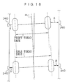
- the wheel alignment adjusting device of the sixth aspect further comprises a control means for controlling the moving device to move the wheel loading portion on which a vehicle left front wheel is loaded and the wheel loading portion on which a vehicle right front wheel is loaded such that a pulled out amount of the connecting member measured by the distance measuring device corresponding to the vehicle right front wheel and a pulled out amount of the connecting member measured by the distance measuring device corresponding to the vehicle left front wheel are the same, and for controlling the moving device to move the wheel loading portion on which a vehicle left rear wheel is loaded and the wheel loading portion on which a vehicle right rear wheel is loaded such that a pulled out amount of the connecting member measured by the distance measuring device corresponding to the vehicle right rear wheel and a pulled out amount of the connecting member measured by the distance measured device corresponding to the vehicle left rear wheel are the same.
- the control device controls the moving means to move the wheel loading portions on which the left and right front wheels are loaded such that a pulled out amount of the connecting member measured by the distance measuring device corresponding to the vehicle right front wheel and a pulled out amount of the connecting member measured by the distance measuring device corresponding to the vehicle left front wheel are the same.
- the control device controls the moving means to move the wheel loading portions on which the left and right rear wheels are loaded such that a pulled out amount of the connecting member measured by the distance measuring device corresponding to the vehicle right rear wheel and a pulled out amount of the connecting member measured by the distance measuring device corresponding to the vehicle left rear wheel are the same.
- the central line of the vehicle body and the central line of the wheel alignment adjusting device can automatically be made to correspond to one another.
- the pull out opening can be moved onto an axis of the wheel.
- the position measuring device has a first case and a second case, and one longitudinal direction end portion of the first case is fixed to a predetermined position of the wheel loading portion such that the first case is rotatable about the one longitudinal end portion, and the first case supports the second case such that the second case is movable in a longitudinal direction of the first case.
- the second case includes: a pull out opening from which the wire is pulled out; an anchoring portion on which another end portion of the wire is anchored; at least one running pulley, a portion of the wire between the pull out opening and the anchoring portion being trained around the running pulley; and an urging device which urges the running pulley in one direction such that tensile force is applied to the wire.
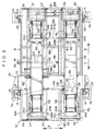
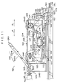
- a wheel alignment adjusting device 10 of the present embodiment includes four supporting pillars 14 which stand vertically upright at a floor surface 12.
- a vertical feed screw 16 is fixed to the supporting pillar 14 in a state of being suspended from an upper portion of the supporting pillar 14.
- a loading stand 18 is disposed between the two supporting pillars 14 at the side in the direction of arrow R and the two supporting pillars 14 at the side in the direction of arrow L.
- the loading stand 18 includes a substantially rectangular main frame 19 which is formed from frame members 18F, 18B, 18R, 18L, 18M, 18N.
- a shaft receiving portion 20 is mounted to a position of a side surface of the main frame 19 which position opposes the supporting pillar 14.
- the female screw of the rotating member 22 screws together with the vertical feed screw 16.
- a sprocket 24 is coaxially fixed to the axial direction upper end portion of the rotating member 22.
- the main frame 19 includes an endless chain 26 which meshes with the sprockets 24.
- the chain 26 is supported by plural sprockets 28 which are rotatably supported at the main frame 19.
- a motor unit 30 which drives the chain 26 is mounted to the main frame 19.
- the chain 26 meshes with a sprocket 32 which is rotated by the motor unit 30.
- the chain 26 rotates the sprockets 24 of the respective supporting pillars 14 simultaneously.
- the respective rotating members 22 rotate simultaneously such that the loading stand 18 is raised along the vertical feed screws 16.
- the loading stand 18 is lowered along the vertical feed screws 16.
- a first sub-base 34R and a first sub-base 34L which extend in the direction of arrow F and in the direction of arrow B, are provided at the upper portion of the main frame 19.
- the first sub-base 34L at the arrow L direction side is fixed to the main frame. 19 by fixing hardware 35 or the like.
- Guide rails 36 which extend along the direction of arrow R and the direction of arrow L, are mounted to the arrow F direction side and the arrow B direction side of the main frame 19.
- a linear shaft receiving portion 37 which is engaged so as to be freely slidable along the guide rail 36, is mounted to each of the longitudinal direction end portions of the first sub base 34R.
- the first sub base 34R is slidable along the direction of arrow R and the direction of arrow L with respect to the main frame 19.
- Load receiving rollers (not shown in the drawings), which roll along the top surfaces of the frame members 18M, 18N which extend along the direction of arrow R and the direction of arrow L, are supported so as to be freely rotatable at the bottom surface of the first sub base 34R.
- a pair of pulleys 38 is rotatably supported at a longitudinal direction intermediate portion of the main frame 19.
- An endless wire rope 40 is trained around the pair of pulleys 38.
- a handle 42 is mounted to one of the pulleys 38 for rotation of that pulley 38.
- a grasping claw 44 which can grasp the wire rope 40, is provided at the first sub-base 34R which is movably supported.
- the grasping claw 44 is connected to a solenoid 46 provided at the first sub-base 34R.
- a solenoid 46 provided at the first sub-base 34R.
- the movably supported first sub-base 34R can be moved in the direction of arrow R and the direction of arrow L.
- a rack 48 is fixed to each of the arrow F direction side frame member 18F and the arrow B direction side frame member 18B.
- a lock device 50 is disposed at each of the arrow F direction side end portion and the arrow B direction side end portion of the movably supported first sub-base 34R.
- the lock device 50 is provided with an wedge-shaped tooth 54 which is driven by a solenoid 52 to move in directions of approaching and moving apart from the rack 48 of the main frame 19. Due to the tooth 54 entering into the space ("valley") between two teeth of the rack 48, the movably supported first sub-base 34R is accurately positioned and fixed, parallel to the first sub-base 34L which is fixed to the main frame 19.
- the solenoid 52 of the lock device 50 is in a non-energized state, and at this time, the tooth 54 is entered into a valley of the rack 48 as illustrated in Fig. 5 (locked state). On the other hand, when the solenoid 52 is energized, the tooth 54 separates from the rack 48 (unlocked state).
- a tire driving device 118 is provided in a vicinity of the arrow F direction side end portion and in a vicinity of the arrow B direction side end portion of the first sub-base 34R and the first sub-base 34L, respectively.
- the internal structure of the tire driving device 118 will be described later.
- the tire driving device 118 at the arrow B direction side of the first sub-base 34R is supported by a mechanism, which will be described layer, so as to be slidable in the direction of arrow F and in the direction of arrow B with respect to the first sub-base 34R.
- the tire driving device 118 at the arrow F direction side of the first sub-base 34R is fixed and does not slide in the direction of arrow F and the direction of arrow B with respect to the first sub-base 34R.
- the tire driving device 118 at the arrow B direction side of the first sub-base 34L is supported, by a mechanism which will be described later, so as to be slidable in the direction of arrow F and in the direction of arrow B with respect to the first sub-base 34L.
- the tire driving device 118 at the arrow F direction side of the first sub-base 34L is fixed and does not slide in the direction of arrow F and the direction of arrow B with respect to the first sub-base 34L.
- a feed screw 56 which extends along the moving direction of the slidably supported tire driving device 118, is rotatably supported at the first sub-base 34R which is supported so as to be movable.
- a nut 58 having a female screw (not shown in the drawings) which screws together with the feed screw 56, is fixed to the slidably supported tire driving device 118.
- the tire driving device 118 having the nut 58 can be moved in the direction of arrow F and in the direction of arrow B.
- a gear 60 is fixed to the arrow B direction side end portion of the feed screw 56.
- first sub-base 34L has the same structure as that of the first sub-base 34R, except for the fact that the first sub-base 34L is fixed to the main frame 19, description of the first sub-base 34L will be omitted.
- a shaft 62 which extends along the arrow R direction and the arrow L direction is rotatably supported at the arrow B direction side of the main frame 19.
- the shaft 62 is formed from two shafts of different diameters.
- a spline shaft portion is provided at the outer surface of the narrow-diameter shaft.
- a spline hole portion, with which the spline shaft portion engages, is formed in the large-diameter shaft.
- a gear 64R which meshes with the gear 60 of the feed screw 56 provided at the first sub-base 34R, is fixed to the arrow R direction end portion of the shaft 62.
- a gear 64L which meshes with the gear 60 of the feed screw 56 provided at the first sub-base 34L, is fixed to the arrow L direction end portion of the shaft 62.
- Rotating driving force from a motor unit 66 provided at the main frame 19 is transferred to the shaft 62 via a chain (not shown in the drawings).
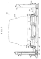
- first transfer plate 68 is fixed to the arrow B direction side tire driving device 118.
- the first transfer plate 68 is formed from a plurality of substantially U-shaped (in cross section) plate members and is expandable and contractible along the direction of arrow F and the direction of arrow B.
- the other end of the first transfer plate 68 is fixed to the arrow B direction side frame member 18B of the main frame 19.
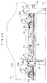
- the upper surface of the tire driving device 118 and the upper surface of the first transfer plate 68 are set at substantially the same height as illustrated in Fig. 8.
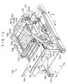
- a second sub-base 70 is provided on the loading stand 18.
- the second sub-base 70 is provided with a horizontal member 72 which extends horizontally so as to span between the two arrow F direction side supporting pillars 14.
- a supporting portion 74 which is formed so as to enclose three side surfaces of the supporting pillar 14, is provided at each of the arrow R direction end portion and the arrow L direction end portion of the horizontal member 72.
- a plurality of guide rollers 76 are rotatably supported at the supporting portion 74 so as to abut three side surfaces of the supporting pillar 14.
- the second sub-base 70 can be moved vertically while being guided by the supporting pillars 14.
- a second transfer plate 78 is provided at each of the arrow R direction side and the arrow L direction side at the top portion of the second sub-base 70.
- the second transfer plate 78 is formed from a plurality of plates, and is extendable in the direction of arrow B from the second sub-base 70.
- the top surface of the second transfer plate 78 and the top surface of the arrow F direction side tire driving device 118 are set to be substantially the same height as illustrated in Fig. 8.
- plate members 82 are provided at the arrow B direction side end portion of the second transfer plate 78.
- a hole which extends vertically is formed in each plate member 82.
- Pins 84 are provided in a vicinity of the upper end of the arrow F direction side of a supporting stand 246 (which will be described later) which is provided at the arrow B direction side tire driving device 118 which is supported so as to be movable.
- the pin 84 can be inserted into the hole of the plate member 82 from below.
- the second transfer plate 78 extends (see Figs. 3 and 9) in a state in which it spans between the second sub-base 70 and the movably supported tire driving device 118.
- the second transfer plate 78 becomes shorter (see Fig. 6).
- the second transfer plate 78 at the arrow L direction side is fixed with respect to the horizontal member 72 such that this second transfer plate 78 does not move in the direction of arrow R and in the direction of arrow L.
- a plurality of guide rollers (not illustrated) are rotatably supported at the arrow R direction side second transfer plate 78. These guide rollers engage with a plurality of guide rails 88 which are provided at the horizontal member 72 and extend in the direction of arrow R and the direction of arrow F. As a result, the second transfer plate 78 at the arrow R direction side can slide in the direction of arrow R and the direction of arrow L with respect to the horizontal member 72.
- the second transfer plate 78 also is moved in the direction of arrow R or in the direction of arrow L, such that the two tire driving devices 118 on the first sub-base 34R and the second transfer plate 78 at the arrow R direction side are always maintained in a relation of being disposed on a straight line.
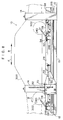
- the second sub-base 70 includes a lock device 90 at each supporting portion 74.
- a lock plate 92 is provided at each supporting pillar 14 corresponding to respective supporting portions 74.
- the lock plate 92 is formed so as to be long in the vertical direction, and a plurality of square holes 94 are formed in the lock plate 92 in the vertical direction at uniform intervals.
- the lock device 90 includes a lock lever 96 which engages with the square holes 94.
- the intermediate portion of the lock lever 96 is supported and is swingable at a shaft receiving portion 98 fixed to the supporting portion 74. A vicinity of a lower end 96A of the lock lever 96 can be inserted into the square holes 94.
- a lower end 94A of the square hole 94 is formed so as to be inclined slightly downward toward the inner side thereof (the supporting pillar 14 side thereof) from the outer side thereof.
- the lower surface in the vicinity of the lower end 96A of the lock lever 96 is formed so as to contact in parallel the lower end 94A of the square hole 94 in a state in which the lower end 96A of the lock lever 96 is inserted into the square hole 94.
- the lock device 90 includes a double-acting air cylinder 102 (i.e., an air cylinder of the type having, at both sides of the piston, an air chamber into which air is made to enter and from which air is made to leave).
- a double-acting air cylinder 102 i.e., an air cylinder of the type having, at both sides of the piston, an air chamber into which air is made to enter and from which air is made to leave.
- the main body of the air cylinder 102 is supported via a pin 105 at a supporting member 103 of the supporting portion 74, such that the air cylinder 102 is swingable.
- a distal end of a piston rod 104 of the air cylinder 102 is connected via a pin 107 to an upper end 96B of the lock lever 96.
- a solenoid valve, a pressure regulating valve, an air compressor and the like are connected to the air cylinder 102.
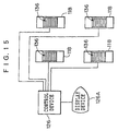
- the operation of the solenoid valve and the air compressor is controlled by a control device 126 which is shown in Fig. 15.
- the control device 126 can be formed by, for example, a microcomputer.
- a display device 126A which is a CRT or the like for displaying the values measured by a force sensor 152 which will be described later and for displaying the adjustment direction of the positional angle of the wheel 302 and the like, is connected to the control device 126.
- the air cylinder 102 urges the lock lever 96, by air pressure, in a direction in which the bottom end 96A of the lock lever 96 approaches the lock plate 92.
- the lower end 96A of the lock lever 96 engages successively with the plurality of square holes 94 while sliding along the lock plate 92 or the side surface of the supporting pillar 14.
- the lower end 96A of the lock lever 96 is inserted into the square hole 94 and the lower end 96A catches on the lower end 94A (the state illustrated by the dotted line in Fig. 10) such that the lowering of the second sub-base 70 is stopped and only the loading stand 18 is lowered.
- the second sub-base 70 When the second sub-base 70 is lowered together with the loading stand 18, first, the second sub-base 70 is supported and lifted slightly from below by the loading stand 18.
- the lower end 96A of the lock lever 96 moves upward so as to separate from the lower end 94A of the square hole 94 of the lock plate 92, and the lock lever 96 becomes slidable.
- the air cylinder 102 is operated and the lock lever 96 rotates so that the lower end 96A comes out from the square hole 94.
- the second sub-base 70 can be lowered together with the loading stand 18 while in a state of being loaded on the loading stand 18.
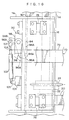
- the tire driving device 118 includes a frame 122.
- One of the drive shafts 124 is connected to a motor 127 whose driving is controlled by the control device 126 (see Fig. 22).
- An endless chain (not shown in the drawings) is trained around the sprocket of one drive shaft 124 and the sprocket of the other drive shaft 124.
- Long, thin plates 132 are connected to the chain continuously along the longitudinal direction of the chain, so as to form an endless track 134.
- the long, thin plate 132 has a length which is sufficiently longer than the width of the tire, and has a width which is of an extent that does not permit the long, thin plate 132 to enter into the grooves of the tread pattern of the tire.
- a plurality of protrusions 138 are formed along the circulating direction, on the outer peripheral surface of the endless track 134, so as to form one protruding portion.
- the tire driving surface 136 the surface formed by the upper surfaces of the plurality of plates 132 is called the tire driving surface 136.
- a supporting frame 148 is disposed beneath the frame 122.
- the frame 122 is disposed on the supporting frame 148 via force sensors 152.
- the force sensor 152 can detect the magnitude and the direction of the force applied to the frame 122 via the endless track 134, and outputs the results of measurement to the control device 126.
- the supporting frame 148 is mounted to the top surface of vehicle transverse direction moving base plate 156.
- a longitudinal direction moving base plate 166 is disposed horizontally beneath the vehicle transverse direction moving base plate 156.
- a pair of guide rails 168 for left and right sliding, which extend along the left and right directions of the vehicle (the direction orthogonal to the surface of the drawing of Fig. 11) are mounted to the top surface of the longitudinal direction moving base plate 166.
- a linear shaft receiving portion 170 is slidably supported at each of the guide rails 168 for left and right sliding.
- the vehicle transverse direction moving base plate 156 is mounted to the linear shaft receiving portions 170.
- the vehicle transverse direction moving base plate 156 is supported so as to be movable along the left and right directions of the vehicle along the guide rails 168 for left and right sliding, with respect to the longitudinal direction moving base plate 166.
- a bracket 172 is mounted to the transverse direction moving base plate 156 so as to protrude in the direction of arrow B.
- a nut (not illustrated), in which a female screw is formed and whose axial direction is along the vehicle left and right directions, is mounted to the distal end portion of the bracket 172.
- a feed screw 178 which is rotatably supported by a shaft receiving portion 176, is provided at the longitudinal direction moving base plate 166.
- a nut is screwed together with the feed screw 178.
- a motor 182 which is mounted to a bracket 180, is provided at the longitudinal direction moving base plate 166.
- a pulley 184 is mounted to the rotating shaft of the motor 182.
- a pulley 186 is mounted to the one end of the feed screw 178 which opposes the pulley 184.
- An endless timing belt 188 is trained about the pulley 184 and the pulley 186.
- the motor 182 is connected to the control device 126 (see Fig. 15). The driving of the motor 182 is controlled by the control device 126.
- the vehicle transverse direction moving base plate 156, the frame 122, the supporting frame 148 and the like integrally move in the left and right directions of the vehicle with respect to the longitudinal direction moving base plate 166.
- a pair of guide rails 190 for longitudinal sliding which extend parallel to one another along the direction of arrow F and the direction of arrow B, are mounted to the top surfaces of the first sub-base 34L and the first sub-base 134R (not illustrated in Figs. 11 and 13).
- a plurality of linear shaft receiving portions 192 which fit together with the guide rails 190 for longitudinal sliding, are mounted to the bottom surface of the longitudinal direction moving base plate 166, such that the tire driving device 118 is supported so as to be movable in the longitudinal direction of the vehicle.
- the nut 58 which screws together with the feed screw 56 is mounted to the longitudinal direction moving base plate 166 of the movably supported tire driving device 118. As a result, by rotating the feed screw 56 as described previously, the movably supported tire driving device 118 can be moved in the longitudinal direction.
- a wheel stopping plate 194F is provided swingably at the frame 122 at the arrow F direction side of the tire driving device 118
- a wheel stopping plate 194B is provided swingably at the frame 122 at the arrow B direction side of the tire driving device 118.
- the wheel stopping plates 194F and 194B are provided so as to straddle across the tire driving device 118 as shown in Fig. 13.
- Driving force of a first cylinder 216 provided on the supporting frame 148 is transferred to the wheel stopping plate 194F via a short link 230 and a link 212 such that the wheel stopping plate 194F swings.
- driving force of a second cylinder 218 provided on the supporting frame 148 is transferred via a link 238 to the wheel stopping plate 194B such that the wheel stopping plate 194B swings.
- the wheel stopping plate 194F and the wheel stopping plate 194B are disposed horizontally. Namely, the wheel stopping plate 194F and the wheel stopping plate 194B are disposed so as to not prevent the wheel from moving on the tire driving device 118.
- the wheel stopping plate 194F and the wheel stopping plate 194B are raised and set at an incline as illustrated in Figs. 12 and 13.
- the driving of the first cylinder 216 and the second cylinder 218 is controlled by the control device 126 (see Fig. 15).
- a left and right connecting device 310 is provided at the two tire driving devices 118 at the arrow B direction side.
- the left and right connecting device 310 is formed from a flat steel member 312 and a nipping device 314.
- One end of the flat steel member 312 is fixed to the arrow L direction side tire driving device 118, and the flat steel member 312 extends toward the arrow R direction side.
- the nipping device 314 is provided at the arrow R direction side tire driving device 118, and fixably nips the flat steel member 312 therewith.
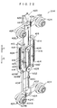
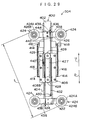
- the jig 304 has a linear slide bearing 400.
- the linear slide bearing 400 has an inner member 402, an outer member 404 and a plurality of steel balls 406.
- the inner member 402 and the outer member 404 are combined so as to be relatively movable along the longitudinal direction.
- a center block 408 and a stopper block 410 are mounted to the outer member 404.
- the center block 408 includes a substantially rectangular parallelepiped main body portion 408A and a plate 408B.
- a grove 412 is formed in the transverse direction central portion of the main body portion 408A.
- the plate 408B is fixed to the main body portion 408A so as to cover the groove 412.
- the linear slide bearing 400 is slidably inserted into a hole portion which has a rectangular cross-section and which is formed by the plate 408B covering the groove 412 of the main body portion 408A.
- the stopper block 410 is formed from a first member 410A, a second member 410B, and a screw 418 having a handle.
- a female screw 420 is formed in the first member 410A.
- the stopper block 410 can be slid in the longitudinal direction of the outer member 404.
- the stopper block 410 can be fixed to any arbitrary position of the outer member 404.
- a grooved pin 414 is fixed to each of the side surfaces of the center block 408 and the side surfaces of the stopper block 410.
- the grooved pin 414 of the center block 408 and the grooved pin 414 of the stopper block 410 are connected by a tension spring 416.
- the tension springs 416 pull the center block 408 and the stopper block 410 in directions of approaching one another. Accordingly, usually, the center block 408 abuts the stopper block 410 (see Figs. 22, 25, 26).
- an elongated hardware 422 with rollers is mounted to the arrow D direction side end portion of the outer member 404 in a direction orthogonal to the longitudinal direction of the outer member 404.
- a flanged roller 424 in which a bearing (not shown in the drawings) is housed, is rotatably mounted to each end portion of the hardware 422 with rollers.
- An elongated hardware 426 with rollers is mounted to the arrow U direction side end portion of the inner member 402 in a direction orthogonal to the longitudinal direction of the inner member 402.
- the flanged roller 424 which is the same as that of the outer member 404, is rotatably mounted to each end portion of the hardware 426 with rollers.
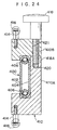
- a flange 424B is provided integrally with one end side of a small-diameter portion 424A.
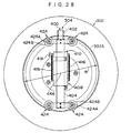
- a portion of the small-diameter portion 424A side surface of the flange 424B abuts the wheel axial direction outer side end of a disk wheel flange (rim flange) 302A of the wheel 302.
- the outer peripheral surface of the small diameter portion 424A abuts the inner peripheral surface of the disk wheel flange 302A.
- a rubber ring 424C for preventing slipping is mounted to the outer peripheral surface of the small-diameter portion 424A as illustrated in Fig. 22.
- a first groove 425 which extends from the arrow U direction side in the direction of arrow D
- a second groove 427 which extends from the arrow D direction side in the direction of arrow U
- the first groove 425 is a relief for a wire anchoring pin 440 which will be described later.
- the second groove 427 is a relief for a wire anchoring pin 430 which will be described later.
- a pulley 428 is mounted so as to be freely rotatable in a vicinity of the arrow U direction side end portion and in a vicinity of the arrow D direction side end portion of the second block 408 on a transverse direction central line of the center block 408.
- the wire anchoring pin 430 is fixed to a vicinity of the arrow D direction side end portion of the inner member 402. One end of a first wire 432 is anchored on the wire anchoring pin 430.
- a wire mounting hardware 434 is mounted to the arrow D direction end portion of the outer member 404.
- a female screw (not shown in the drawings) is formed in the wire mounting hardware 434.
- a long screw 436 is screwed into this female screw.
- the other end of the first wire 432 is anchored on an end portion of the long screw 436.
- An intermediate portion of the first wire 432 is trained around the arrow U direction side pulley 428.
- Two nuts 438 for preventing loosening are screwed together with the long screw 436.
- the wire anchoring pin 440 is fixed to the substantially intermediate portion in the longitudinal direction of the outer member 404.
- One end of a second wire 442 is anchored to the wire anchoring pin 440.
- a wire mounting hardware 444 is mounted to the hardware 426 with rollers, of the inner member 402.
- a long screw 436 and nuts 438 are mounted to the wire mounting hardware 444.
- the other end of the second wire 442 is anchored to the long screw 436.
- An intermediate portion of the second wire 442 is trained around the arrow D direction side pulley 428.
- the tension springs 416 extend and urge the arrow U direction side flanged rollers 424 and the arrow D direction side flanged rollers 424 in directions of moving apart.
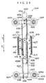
- a swivel (torsion preventer) 448 is anchored, via a hook 446, to a portion of the center block 408 between the arrow U direction side flanged rollers 424 and the arrow D direction side flanged rollers 424.
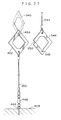
- the hook 446 is fixed to the center of the center block 408, and is always positioned between the arrow U direction side flanged rollers 424 and the arrow D direction side flanged rollers 424. As shown in Fig. 21 and Fig. 28, when the four flanged rollers 424 abut the inner peripheral surface of the disk wheel flange 302A of the wheel 302, the hook 446 is always positioned on an imaginary line extending from the rotational axis of the wheel 302.
- One end of a first wire 450 for measurement is connected to the other end of the swivel 448.
- a first anchoring hardware 452 which is formed as a substantially diamond-shaped frame, is connected to the other end of the first wire 450 for measurement.
- a notch 454 which has a width corresponding to the plate thickness of a second anchoring hardware 546 which will be described later, is formed at the side of the hole portion of the first anchoring hardware 452 which side is opposite the side at which the first wire 450 for measurement is connected.
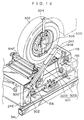
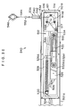
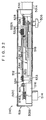
- a distance measuring device 240 is provided at each tire driving device 118.
- the distance measuring device 240 includes a rod 501 which is freely extendible and contractible.
- the rod 501 is formed by a first case 501A which is elongated and has a substantially U-shaped cross-sectional configuration, and a second case 501B which is formed in an elongated, box-shaped configuration and is inserted in the first case 501A so as to be freely slidable therein.
- One side surface of the second case 501B is open, and the open portion is usually closed by a cover 501C being mounted to the second case 501B by screws.
- a cylindrical base portion 500 is mounted integrally to one end of the first case 501A.
- a female screw (not shown in the drawings) is formed on the side surface of the supporting stand 246.
- the rod 501 is rotatable around the male screw portion of the screw 502 to which the lever is attached.
- the screw 502 to which a lever is attached is rotated and the male screw is screwed into the female screw, the base portion 500 is pushed against the side surface of the supporting stand 246, and the rod 501 is thereby fixed at an arbitrary orientation.
- a long hole 504 is formed in the first case 501A along the longitudinal direction thereof.
- the second case 501B is fixed to the first case 501A.
- the male screw 508 is loosened, the second case 501B can move along the longitudinal direction.
- the second case 501B is provided with a distance measuring means 512.
- the distance measuring means 512 has a block 516 which fixes a rotary encoder 514 at a distal end side of the second case 501B.
- a pulley 514B is mounted to a rotating shaft 514A of the rotary encoder 514.
- a small pulley 517 is rotatably provided at the block 516 in a vicinity of the pulley 514B.
- a linear slide bearing 525 is mounted to the second case 501B at the side of the rotary encoder 514.
- the linear slide bearing 525 has an elongated first member 518, an elongated second member 520 and an intermediate member 522.
- a plurality of steel balls 524 are disposed between the first member 518 and the intermediate member 522, and between the second member 520 and the intermediate member 522.
- the second member 520 is fixed to the second case 501B, and the first member 518 freely slides smoothly along the longitudinal direction of the second member 520.
- a plate member 526 is fixed to the first member 518.
- One end of a tension spring 528 is anchored on a projection 526A provided at a side portion of the plate member 526.
- the other end of the tension spring 528 is anchored on a pin 530 which is fixed to the second case 501B and which is provided at the side opposite the rotary encoder 514 side.
- the plate member 526 and the first member 518 are always pulled toward the pin 530 side.
- a pulley 532A and a pulley 532B are mounted, so as to be freely rotatable and so as to be disposed one on the other, to the center of the plate member 526.
- a shaft 533 which is fixed to the second case 501B, is provided between the second member 520 and the rotary encoder 514.
- a pulley 534 is rotatably mounted to the shaft 533.
- a wire opening 536 is provided at the side surface of the second case 501B.
- the wire opening 536 has a hollow shaft 538 which is hollow and fixed to the side surface of the second case 501B.
- a male screw is formed at a portion of the outer peripheral surface of the hollow shaft 538.
- a second wire 544 for measurement is inserted through the hollow shaft 538 of the wire opening 536.
- the second wire 544 for measurement which extends from the wire opening 536 toward the interior of the second case 501B, is first trained around the pulley 514B of the rotary encoder 514 and the small pulley 517, and around the pulley 514B again in a clockwise direction, and thereafter, is trained around the pulley 532A, the pulley 534 and the pulley 532B, and thereafter, the end portion is anchored on the shaft 533 which is fixed to the second case 501B and which supports the pulley 534.
- the second anchoring hardware 546 which is formed in a substantially diamond-like frame shape and which engages with the first anchoring hardware 452, is mounted to the end portion of the second wire 544 for measurement which extends from the wire opening 536 toward the outer side of the second case 501B.
- a notch 548 which is of a thickness corresponding to the plate thickness of the first anchoring hardware 452, is formed at a portion of the second anchoring hardware 546 at the side of the hole portion, which side is opposite the side at which the second anchoring hardware 546 is connected with the second wire 544 for measurement.
- a cut-out 550 which passes through from the exterior to the interior (or from the interior to the exterior) of the frame portion, is formed in one portion of the second anchoring hardware 546. The cut-out 550 is substantially closed, and opens by the second anchoring hardware 546 being elastically deformed.
- a stopper hardware 552 is fixed by caulking to the intermediate portion of the second wire 544 for measurement which extends from the wire opening 536 toward the outer side of the second case 501B.
- tension for pulling-in the second wire 544 for measurement from the wire opening 536 into the second case 501B, is applied to the second wire 544 for measurement.
- the pulley 532A and the pulley 532B, around which the second wire 544 for measurement is trained serve as a running pulley (the other pulleys serve as fixed pulleys).
- the dimension of movement of the pulley 532A and 532B is 1/4 of the dimension over which the second wire 544 for measurement is pulled out from the wire opening 536 toward the outer side.
- the second wire 544 for measurement is trained around the pulley 514B of the rotary encoder 514 with tension applied to the second wire 544 for measurement.
- the rotating shaft 514A of the rotary encoder 514 rotates by an angle which corresponds to the amount by which the second wire 544 for measurement is pulled out.
- Fig. 30 and Fig. 33 illustrate the state in which the second wire 544 for measurement is pulled out.
- the stopper hardware 552 abuts the end portion of the wire opening 536, and as illustrated in Fig. 32, the first member 518 to which the pulley 532A and the pulley 532B are mounted is positioned at the pin 530 side. (Even in the state in which the stopper hardware 552 abuts the end portion of the wire opening 536, tension is applied to the second wire 544 for measurement.)
- the rotary encoder 514 converts the angle of rotation of the rotating shaft 514A into an electric signal, and outputs the results of measurement to the control device 126.
- the pulled-out amount of the second wire 544 for measurement is thereby measured precisely and accurately.
- the distance measuring means 512 is set such that, in a state in which the stopper hardware 552 abuts the end portion of the wire opening 536, the pulled-out amount of the second wire 544 for measurement is set to zero. Operation
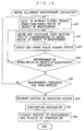
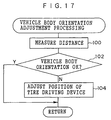
- the orientation of the vehicle 300 is corrected by detecting the positions of the wheels 302 by using the distance measuring devices 240.
- the wheel 302 is inclined such that the distance to the wheel 302 (the pulled-out amount of the second wire 544 for measurement) is changed.
- the amount of change in the angle of the wheel 302 can be determined by calculation using a trigonometric function, from the amount of change in the distance to the wheel 302.
- the pulled-out amount of the second wire 544 for measurement can be increased, or the length of the distance measuring device 240 can be made shorter.
- stainless wires are preferably used for the first wire 450 for measurement and the second wire 544 for measurement.
- another material may be used provided that it does not stretch due to tension spring 528 such that the precision of measurement deteriorates, and provided that it is difficult for the material to change over the years.
- the position of a wheel can be detected precisely and with high accuracy.
- a position of a wheel can be detected precisely and with high accuracy.
- the wire can be freely bent, it is easy to accommodate the wire compactly within the distance measuring device, and the distance measuring device can be made compact.
- the pulled-out amount of the wire can be measured precisely and accurately.
- the position of a vehicle body can be corrected automatically.
- the central line of a vehicle body and the central line of the wheel alignment adjusting device can automatically be made to coincide with one another.
Landscapes
- Physics & Mathematics (AREA)
- General Physics & Mathematics (AREA)
- Body Structure For Vehicles (AREA)
- Length Measuring Devices With Unspecified Measuring Means (AREA)
- A Measuring Device Byusing Mechanical Method (AREA)
Applications Claiming Priority (2)
| Application Number | Priority Date | Filing Date | Title |
|---|---|---|---|
| JP11203384A JP2001033234A (ja) | 1999-07-16 | 1999-07-16 | タイヤ位置検出装置及びホイールアライメント調整装置 |
| JP20338499 | 1999-07-16 |
Publications (2)
| Publication Number | Publication Date |
|---|---|
| EP1069402A2 true EP1069402A2 (de) | 2001-01-17 |
| EP1069402A3 EP1069402A3 (de) | 2001-11-07 |
Family
ID=16473155
Family Applications (1)
| Application Number | Title | Priority Date | Filing Date |
|---|---|---|---|
| EP00305980A Withdrawn EP1069402A3 (de) | 1999-07-16 | 2000-07-14 | Vorrichtung zur Positionsbestimmung von Reifen und Einstellvorrichtung zum Radausrichten |
Country Status (3)
| Country | Link |
|---|---|
| US (1) | US6453567B1 (de) |
| EP (1) | EP1069402A3 (de) |
| JP (1) | JP2001033234A (de) |
Cited By (5)
| Publication number | Priority date | Publication date | Assignee | Title |
|---|---|---|---|---|
| WO2005008172A1 (de) * | 2003-07-18 | 2005-01-27 | Lasatron Ag | Verfahren und vorrichtung zur messung der lenkgeometrie von fahrzeugen |
| WO2014068239A1 (fr) * | 2012-10-29 | 2014-05-08 | Mi Systems | Banc d'essais pour vehicule automobile |
| EP2637156A4 (de) * | 2010-11-05 | 2016-11-09 | Eizo Corp | Mechanismus zur betätigung einer sensoreinheit und flüssigkristallanzeigemechanismus zur betätigung einer sensoreinheit |
| CN118463889A (zh) * | 2024-07-08 | 2024-08-09 | 太原理工天成电子信息技术有限公司 | 一种矿压顶板离层量测量装置 |
| CN120361956A (zh) * | 2025-04-22 | 2025-07-25 | 广东立佳实业有限公司 | 一种四驱四电机台架整车环境舱及其控制系统 |
Families Citing this family (18)
| Publication number | Priority date | Publication date | Assignee | Title |
|---|---|---|---|---|
| US7249418B2 (en) * | 2004-11-12 | 2007-07-31 | Hella KG a.A. Hueck & Co. | Wheel position sensor |
| US7150105B1 (en) | 2005-01-12 | 2006-12-19 | Honda Motor Co., Ltd. | Adaptor for use in vehicle wheel alignment |
| JP4697430B2 (ja) * | 2006-01-19 | 2011-06-08 | 株式会社アドヴィックス | タイヤ前後力推定装置 |
| US20080173080A1 (en) * | 2006-07-17 | 2008-07-24 | Strauser John W | Nascar body dimension or configuration measuring device |
| JP2008185464A (ja) * | 2007-01-30 | 2008-08-14 | Hiwin Mikrosystem Corp | アクチュエータ用リニアフィードバック装置 |
| JP2009035081A (ja) * | 2007-07-31 | 2009-02-19 | Equos Research Co Ltd | 制御装置 |
| ES2388188T3 (es) * | 2008-01-09 | 2012-10-10 | Siemens Aktiengesellschaft | Centrado de vehículo en el estado de ajuste del mecanismo de traslación y procedimiento correspondiente |
| US8069576B2 (en) * | 2008-03-17 | 2011-12-06 | Honda Motor Co., Ltd. | Vehicle wheel alignment measuring method and apparatus |
| KR101345906B1 (ko) * | 2012-01-13 | 2013-12-30 | 현대위아 주식회사 | 횡강성 측정용 센서 거치대, 횡강성 측정용 센서 장치 및 횡강성 측정장치 |
| DE102015224636A1 (de) * | 2015-12-08 | 2017-06-08 | Zf Friedrichshafen Ag | Radkraftdynamometer zur Messung von Reifenkräften |
| CN107328351A (zh) * | 2017-07-31 | 2017-11-07 | 中信戴卡股份有限公司 | 一种车轮法兰检测装置 |
| KR102485394B1 (ko) * | 2017-12-11 | 2023-01-05 | 현대자동차주식회사 | 자동차 및 그 제어 방법 |
| CN111457828B (zh) * | 2020-05-06 | 2021-10-29 | 内蒙古农业大学 | 一种汽车四轮定位夹具套件 |
| CN112129326A (zh) * | 2020-10-20 | 2020-12-25 | 浙江省交通运输科学研究院 | 一种检测车编码器系统 |
| CN113883988B (zh) * | 2021-09-22 | 2023-07-14 | 中国北方车辆研究所 | 动力装置传动中心双输出高精度对中装置 |
| CN114264489B (zh) * | 2021-11-12 | 2023-08-08 | 上海工程技术大学 | 一种列车空气制动摩擦副模拟系统 |
| CN115857039A (zh) * | 2022-11-28 | 2023-03-28 | 西安科技大学 | 一种用于机场异物检测车的测量轮起落装置 |
| CN119305655B (zh) * | 2024-09-26 | 2025-10-31 | 奇瑞汽车股份有限公司 | 一种汽车后悬架四轮定位调整装置 |
Family Cites Families (17)
| Publication number | Priority date | Publication date | Assignee | Title |
|---|---|---|---|---|
| US3181248A (en) * | 1963-03-19 | 1965-05-04 | Maxwell B Manlove | Wheel alignment apparatus |
| US4236315A (en) * | 1978-09-13 | 1980-12-02 | Nortron Corporation | Sensor assembly for wheel alignment system |
| DE3206646C2 (de) * | 1982-02-24 | 1983-12-29 | Osmond 8000 München Beissbarth | Radstellungs-Meßvorrichtung |
| US4800651A (en) * | 1983-06-13 | 1989-01-31 | The Firestone Tire & Rubber Company | Vehicle alignment system |
| FR2575549B1 (fr) * | 1984-12-31 | 1988-10-14 | Facom | Procede et dispositif de mesure de l'angle de braquage d'une roue avant de vehicule automobile |
| US4679327A (en) * | 1986-07-07 | 1987-07-14 | Chrysler Motors Corporation | Front wheel drive vehicle, automatic toe set alignment system, therefor |
| EP0270705B1 (de) * | 1986-12-15 | 1991-04-03 | Osmond Beissbarth | Vorrichtung zur Messung des Einschlagwinkels eines lenkbaren Rades eines Kraftfahrzeugs |
| JPS63165705A (ja) * | 1986-12-26 | 1988-07-09 | Honda Motor Co Ltd | ト−ゲ−ジ |
| CA2005348C (en) * | 1988-12-14 | 1994-09-20 | Yutaka Fukuda | Vehicle composite test apparatus |
| JPH0396803A (ja) * | 1989-09-09 | 1991-04-22 | Mazda Motor Corp | 車両のホイールアライメントの測定装置 |
| US5111585A (en) * | 1989-11-21 | 1992-05-12 | Iyasaka Seiki Co., Ltd. | Method and apparatus for measuring and adjusting the wheel alignment of automotive vehicles |
| JPH0735652A (ja) | 1993-07-20 | 1995-02-07 | Banzai:Kk | ホイールアライメントの測定方法 |
| JP3770505B2 (ja) | 1996-04-10 | 2006-04-26 | 安全自動車株式会社 | 車両車輪の非接触式アライメント測定装置 |
| JP3053570B2 (ja) * | 1996-04-26 | 2000-06-19 | 日産アルティア株式会社 | ローリングサスペンションテスタ |
| JPH09329433A (ja) | 1996-06-10 | 1997-12-22 | Anzen Motor Car Co Ltd | 車両車輪の非接触アライメント測定装置 |
| JP3857358B2 (ja) * | 1996-06-25 | 2006-12-13 | 株式会社ブリヂストン | 車両のホイールアライメント調整方法 |
| JP4160662B2 (ja) * | 1998-07-29 | 2008-10-01 | 株式会社ブリヂストン | 車両のホイールアライメント調整方法 |
-
1999
- 1999-07-16 JP JP11203384A patent/JP2001033234A/ja active Pending
-
2000
- 2000-07-14 EP EP00305980A patent/EP1069402A3/de not_active Withdrawn
- 2000-07-17 US US09/617,833 patent/US6453567B1/en not_active Expired - Lifetime
Cited By (5)
| Publication number | Priority date | Publication date | Assignee | Title |
|---|---|---|---|---|
| WO2005008172A1 (de) * | 2003-07-18 | 2005-01-27 | Lasatron Ag | Verfahren und vorrichtung zur messung der lenkgeometrie von fahrzeugen |
| EP2637156A4 (de) * | 2010-11-05 | 2016-11-09 | Eizo Corp | Mechanismus zur betätigung einer sensoreinheit und flüssigkristallanzeigemechanismus zur betätigung einer sensoreinheit |
| WO2014068239A1 (fr) * | 2012-10-29 | 2014-05-08 | Mi Systems | Banc d'essais pour vehicule automobile |
| CN118463889A (zh) * | 2024-07-08 | 2024-08-09 | 太原理工天成电子信息技术有限公司 | 一种矿压顶板离层量测量装置 |
| CN120361956A (zh) * | 2025-04-22 | 2025-07-25 | 广东立佳实业有限公司 | 一种四驱四电机台架整车环境舱及其控制系统 |
Also Published As
| Publication number | Publication date |
|---|---|
| JP2001033234A (ja) | 2001-02-09 |
| US6453567B1 (en) | 2002-09-24 |
| EP1069402A3 (de) | 2001-11-07 |
Similar Documents
| Publication | Publication Date | Title |
|---|---|---|
| US6453567B1 (en) | Tire position detecting device and wheel alignment adjusting device | |
| EP0816801B1 (de) | Verfahren zum Berichtigen der Ausrichtung von Kraftfahrzeugrädern | |
| JP4160662B2 (ja) | 車両のホイールアライメント調整方法 | |
| US4962664A (en) | Roller clamp type wheel examining apparatus | |
| US6658749B2 (en) | 3D machine vision measuring system with vehicle position adjustment mechanism for positioning vehicle | |
| US6374159B1 (en) | Vehicle wheel alignment adjustment method | |
| US6460259B1 (en) | Wheel alignment adjusting device | |
| CN1938573A (zh) | 轮胎平衡设备 | |
| US7040026B2 (en) | Wheel runout measuring method | |
| US6564461B1 (en) | Wheel alignment adjusting device | |
| US5105547A (en) | Method of and apparatus for measuring the wheel alignment of automotive vehicles | |
| CN121311749A (zh) | 滚轮组件、具有至少一个滚轮组件的车辆测试台以及用于运行此车辆测试台的方法 | |
| JP4267766B2 (ja) | ホイールアライメント調整装置 | |
| CN116045856A (zh) | 一种用于测量电梯导轨用热轧型钢精度的检测装置 | |
| JP4267764B2 (ja) | ホイールアライメント調整装置 | |
| JPH045938B2 (de) | ||
| JPH0611417A (ja) | 走行車の試験台 | |
| JP2504982B2 (ja) | ホイ−ルアライメントの測定方法 | |
| JPH045934B2 (de) | ||
| JPH045937B2 (de) | ||
| JPH045933B2 (de) |
Legal Events
| Date | Code | Title | Description |
|---|---|---|---|
| PUAI | Public reference made under article 153(3) epc to a published international application that has entered the european phase |
Free format text: ORIGINAL CODE: 0009012 |
|
| AK | Designated contracting states |
Kind code of ref document: A2 Designated state(s): AT BE CH CY DE DK ES FI FR GB GR IE IT LI LU MC NL PT SE Kind code of ref document: A2 Designated state(s): DE ES FR GB IT |
|
| AX | Request for extension of the european patent |
Free format text: AL;LT;LV;MK;RO;SI |
|
| PUAL | Search report despatched |
Free format text: ORIGINAL CODE: 0009013 |
|
| AK | Designated contracting states |
Kind code of ref document: A3 Designated state(s): AT BE CH CY DE DK ES FI FR GB GR IE IT LI LU MC NL PT SE |
|
| AX | Request for extension of the european patent |
Free format text: AL;LT;LV;MK;RO;SI |
|
| RIC1 | Information provided on ipc code assigned before grant |
Free format text: 7G 01B 11/275 A, 7G 01B 5/255 B, 7G 01B 7/315 B, 7G 01M 17/007 B |
|
| 17P | Request for examination filed |
Effective date: 20011204 |
|
| AKX | Designation fees paid |
Free format text: DE ES FR GB IT |
|
| 17Q | First examination report despatched |
Effective date: 20041206 |
|
| STAA | Information on the status of an ep patent application or granted ep patent |
Free format text: STATUS: THE APPLICATION IS DEEMED TO BE WITHDRAWN |
|
| 18D | Application deemed to be withdrawn |
Effective date: 20060815 |