EP1069367A1 - Appareil de perçage pour tuyaux - Google Patents
Appareil de perçage pour tuyaux Download PDFInfo
- Publication number
- EP1069367A1 EP1069367A1 EP20000108580 EP00108580A EP1069367A1 EP 1069367 A1 EP1069367 A1 EP 1069367A1 EP 20000108580 EP20000108580 EP 20000108580 EP 00108580 A EP00108580 A EP 00108580A EP 1069367 A1 EP1069367 A1 EP 1069367A1
- Authority
- EP
- European Patent Office
- Prior art keywords
- pipe
- cutting sleeve
- drill
- tapping fitting
- wall
- Prior art date
- Legal status (The legal status is an assumption and is not a legal conclusion. Google has not performed a legal analysis and makes no representation as to the accuracy of the status listed.)
- Granted
Links
Images

Classifications
-
- F—MECHANICAL ENGINEERING; LIGHTING; HEATING; WEAPONS; BLASTING
- F16—ENGINEERING ELEMENTS AND UNITS; GENERAL MEASURES FOR PRODUCING AND MAINTAINING EFFECTIVE FUNCTIONING OF MACHINES OR INSTALLATIONS; THERMAL INSULATION IN GENERAL
- F16L—PIPES; JOINTS OR FITTINGS FOR PIPES; SUPPORTS FOR PIPES, CABLES OR PROTECTIVE TUBING; MEANS FOR THERMAL INSULATION IN GENERAL
- F16L41/00—Branching pipes; Joining pipes to walls
- F16L41/04—Tapping pipe walls, i.e. making connections through the walls of pipes while they are carrying fluids; Fittings therefor
-
- Y—GENERAL TAGGING OF NEW TECHNOLOGICAL DEVELOPMENTS; GENERAL TAGGING OF CROSS-SECTIONAL TECHNOLOGIES SPANNING OVER SEVERAL SECTIONS OF THE IPC; TECHNICAL SUBJECTS COVERED BY FORMER USPC CROSS-REFERENCE ART COLLECTIONS [XRACs] AND DIGESTS
- Y10—TECHNICAL SUBJECTS COVERED BY FORMER USPC
- Y10T—TECHNICAL SUBJECTS COVERED BY FORMER US CLASSIFICATION
- Y10T137/00—Fluid handling
- Y10T137/598—With repair, tapping, assembly, or disassembly means
- Y10T137/612—Tapping a pipe, keg, or apertured tank under pressure
- Y10T137/6123—With aperture forming means
-
- Y—GENERAL TAGGING OF NEW TECHNOLOGICAL DEVELOPMENTS; GENERAL TAGGING OF CROSS-SECTIONAL TECHNOLOGIES SPANNING OVER SEVERAL SECTIONS OF THE IPC; TECHNICAL SUBJECTS COVERED BY FORMER USPC CROSS-REFERENCE ART COLLECTIONS [XRACs] AND DIGESTS
- Y10—TECHNICAL SUBJECTS COVERED BY FORMER USPC
- Y10T—TECHNICAL SUBJECTS COVERED BY FORMER US CLASSIFICATION
- Y10T408/00—Cutting by use of rotating axially moving tool
- Y10T408/65—Means to drive tool
- Y10T408/675—Means to drive tool including means to move Tool along tool-axis
- Y10T408/6793—Screw coaxial with Tool
Definitions
- the invention relates to a pipe tapping fitting for a media-promoting A tube comprising a housing which is at an angle to the tube axis attachable drill nozzle for drilling the pipe wall and one under one Has angle to the drill nozzle arranged branch connector, wherein in Drill socket a rotatably actuated cutting sleeve is arranged, the Cutting sleeve and the drill socket complementary thread have and wherein at least one between the drill socket and the cutting sleeve Sealant to seal the media-conveying pipe from the outside is provided.
- a pipe tapping fitting is known from DE 196 30 029 A1, the Cutting sleeve has both a cutting function and a sealing function.
- the Sealing function is achieved by elastic sealing rings, which are in radial grooves on the Outside of the cutting sleeve in the area of an external thread are arranged and a complementary internal thread of the drill socket slide along.
- the internal thread extends over a length that a Is many times longer than the thickness of the sealing ring. On this length the elastic sealing ring from the internal thread with repeated insertion and Unscrew easily cut and damaged. The great length also leads to a large overall height.
- the pipe tapping valve has the highest possible pressure Funds can withstand. This is achieved in that the Sealant between the drill socket and the cutting sleeve radially inwards and spaced from the complementary threads. The force on the elastic sealant acts, increases with the diameter of the Sealant.
- the pipe tapping fitting is manufactured as simply as possible can be.
- This is achieved in that the sealant between the Drill neck of the housing and the cutting sleeve in a uniform and from Thread spaced sealing area of the cutting sleeve is arranged.
- This is also achieved in that the sealing area on an inner wall the cutting sleeve is designed and that the thread as an external thread an outer wall of the cutting sleeve is formed.
- the pipe tapping fitting is as low as possible Has overall height. This is achieved in that the drill socket is a annular receiving pocket for receiving the sealing area and the Has thread area. The overall height of the pipe tapping valve remains despite Add the sealing area the same size or smaller than existing ones Fittings.
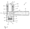
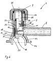
- a pipe tapping fitting 1 is shown half-cut.
- the Pipe tapping fitting 1 is essentially a pipe fitting with three Exits and with internals.
- the pipe tapping fitting 1 comprises a housing 2, which has a drill socket 3 which is perpendicular to the pipe axis media-promoting tube can be attached.
- the media-promoting pipe is not shown here and can promote gas, water or another medium.
- the pipe tapping fitting 1 is used for a branching pipeline, for example a connection line for a house from a main line, for example to branch off a supply line in the street underground.
- the connection process can be carried out without interruption the promotion of the medium that is promoted in the main management and without a loss of the medium.
- gas or Chemical delivery lines it is important for environmental reasons, to be able to work without losing the medium if possible.
- the drill socket 3 has a connection area 5 at a lower end 4 with which the drill socket 3 is connected to the pipe, not shown can be.
- the connection of the drill socket 3 with the pipe can for example with a pipe clamp, with plastic pipes with one electro-weldable saddle part or with another known Connection methods are made.
- an operating opening 7 is shown at the upper end 6 of the drill socket 3 .
- the operating opening 7 serves as Access for a tool that is used to connect the pipe tapping fitting 1 must be inserted into the main pipe in the drill socket 3.
- a branch pipe 8 is arranged at an angle to the drill pipe 3.
- the branch pipe 8 approximately at right angles to the drill pipe 3 arranged. However, depending on the conditions at the installation location, they are also angles larger or smaller than 90 ° conceivable. This ensures that the Connection line that must be connected to the branch connector 8 can be connected to the main line if possible without diversion.
- the Connection cable which was also not shown here, can be used with the same Connection method as described above with the branch pipe 8 get connected.
- the pipe tapping fitting 1 is in one state shown how the valve is delivered ready for installation on site becomes.
- a cutting sleeve 9 is shown as an installation in the drill socket 3.
- the Cutting sleeve 9 is essentially a cylindrical component that is concentric is arranged in the drill socket 3.
- the cutting sleeve 9 comprises from below up four areas: a cutting area 10, which as a core drill or a cutting sleeve 11 is formed, a drive region 12 in which a Tool for actuating the cutting sleeve 9 can be included, a Threaded area 13 with which the cutting sleeve 9 axially and radially in the Drill neck 3 is movable and a spatially from the threaded region 13th separate sealing area 19 which the cutting sleeve 9 to the drill socket 3 of the Seals housing 2.
- the drive area 12 has a tool holder 14 on the inside.
- the tool holder 14 is designed in such a way that a tool can be passed through the Operating opening 7 is inserted into the drill neck 3 from the Tool holder 14 is enclosed.
- the tool can be a normal one Allen key or a special tool. With this tool the cutting sleeve 9 is screwed in or out with respect to the drill socket 3, as is the case with a core drill.
- the drive area 12 can also be a Have end plate 15, with which the medium is prevented from the Main line can flow in the area of the control opening 7.
- the Operating opening 7 can also be closed with a Screw cap or an end cap, which is shown in Figure 6.
- the cutting sleeve 11 is made of a material that is suitable for the wall of the media-promoting pipe. Made of plastic pipes Polyethylene or polypropylene is sufficient with a cylindrical brass sleeve 11 ground cutting edge 16. Only the cutting area 10 is made of metal manufactured. The remaining areas of the cutting sleeve 9 can be the same Plastic material such as the housing 2 or from a compatible one Plastic material are made. If a heavier version if desired, the entire cutting sleeve 9 can also be made of the same Material, such as brass, are made. The cutting area 10 is as thin-walled as possible and takes that on the inside Plastic part on that from the wall of the media-promoting pipe was cut out.
- the cutting sleeve 11 has on the inside Special thread 17, which is used when drilling the pipe Take out cut plastic part in the cutting sleeve 11. With the Special thread 17 is further prevented that when unscrewing the pipe cut plastic part within the cutting sleeve 9 in one Inclined position tilts or even falls back from the cutting sleeve 9 into the tube.
- the threaded area 13, like the cutting sleeve 11, is cylindrical, but not necessarily made of metal or brass. With the threaded area 13 the cutting sleeve 9 is rotatably and operably arranged in the drill neck 3.
- the threaded area 13 of the cutting sleeve 9 has on the outside External thread 18 and a sealing area 19 on the inside.
- the Drill neck 3 has an internal thread 20 which is complementary to External thread 18 of the cutting sleeve 9 is formed.
- the drill socket 9 has a annular receiving pocket 21 on both the entire sealing area 19th as well as the complementary threads 18, 20 for the most part.
- annular design of the receiving pocket 21 ensures that both the Sealing area 19 as well as the complementary threads 18, 20 at the narrowest Space can be arranged. This will increase the overall height of the Pipe tapping fitting 1 kept as small as possible.
- the sealing area 19 of the cutting sleeve 9 has an annular groove 22 Inclusion of a sealant 23.
- the sealant is for example an O-ring seal 23, which is available in many standard sizes.
- the ring groove 22 is arranged in the cylindrical sealing region 19, which is spatially separated of the complementary threads 18, 20 formed on the cutting sleeve 9 is. Due to the spatially separate arrangement of the sealing area 19 and Threads 18, 20 become simple to manufacture and material-saving Sizing of the cutting sleeve possible.
- the wall parts, the sealing functions have to be designed for this task and on the other hand, the wall parts which have the threads 18, 20 can be exactly for that task can be interpreted.
- the inner wall of the cutting sleeve 9 and closer to the Center axis of the drill socket 3 lying wall of the receiving pocket 21 as possible can be formed smooth and uniform. This will make one possible good sealing effect between the drill socket 3 and the cutting sleeve 9 is achieved, so that the pipe tapping fitting 1 can also be used for high media pressures.
- the formation of the annular receiving pocket 21 of the drill socket 3 with the Internal thread 20 can be simplified by manufacturing the Drill neck 3 in two parts. By manufacturing in individual parts, the Inside of the receiving pocket can be processed or deformed more easily and the individual parts can then be glued, welded or Screwed together to form an annular receiving pocket 21 become.
- the annular grooves 22 and the O-ring seals 23 can instead of on Sealing area 19 of the cutting sleeve 9, also on the opposite Wall areas of the drill socket 3 of the housing 2 may be formed.
- the sealant 23 is arranged on a diameter that is essential is smaller than the diameter of the complementary threads 18, 20. As a result the sealing effect of the fitting 1 is further improved, since with a smaller one Diameter the forces occurring at the sealant 23 become smaller.
- the largest diameter, i.e. the Outer diameter of the O-ring seal 23 is smaller than the smallest Diameter, i.e. the inside diameter of the complementary threads 18, 20. Because the complementary threads 18, 20 compared to the O-ring seal 23 the operation will also have a relatively large diameter the cutting sleeve 9 much easier. The feed of the cutting sleeve 9 becomes, at the same pitch angle, proportional to the diameter of the complementary threads 18, 20 larger per revolution.
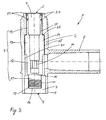
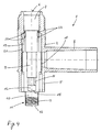
- FIGS Pipe tapping fitting 1 A second exemplary embodiment is shown in FIGS Pipe tapping fitting 1 according to the invention is shown.
- the cutting sleeve 9 has a different design than in Figures 1 and 2.
- the sealing area 19 is also spatially separated from the complementary threads 18, 20 arranged. The spatial separation is even more pronounced here than in the figures 1 and 2.
- the cutting sleeve 9 then points to the outer one Thread 18, which on a first wall region 24 of the cutting sleeve 9th is formed, a second wall area 25, which has a shoulder is connected to the first wall area 24.
- the sealant 23 is on this second wall region 25 of the cutting sleeve 9.
- the Sealant 23 is also arranged on a circle, with a Outside diameter that is smaller than the inside diameter of the Sealing area 19.
- the embodiment of Figures 3 to 5 stands out by good guidance of the cutting sleeve 9 when screwing in and out.
- the sealing effect can be further increased by a second O-ring seal 23 in a second annular groove 22 in the sealing area 19 of the cutting sleeve 9 correct dimensioning of the length ratios of the sealing area 19 and the complementary thread 18, 20 and by the arrangement of the annular grooves 22nd With the O-ring seals 23 at the right height, the overall height can be reduced to one Minimum be limited.
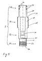
- a further pipe tapping fitting is connected to a media-promoting tube 30 shown.
- the Cutting sleeve 9 shown in a state in which the cutting sleeve 9 the media-promoting tube 30 has completely cut.
- the right half of Figure 6 shows the cutting sleeve 9 in a state in which the Cutting sleeve 9 the passage of the media-conveying pipe in the Branch connector 8 releases completely.
- the tapping fitting 1 from FIG. 6 can be opened different types are connected to the media-promoting tube 30, In Figure 6 this is indicated by an adhesive 31, by a Electrical welding connection 32 and through a pipe clamp half 33.
- Die Cutting sleeve 9 is in the manufacture from below into the pipe tapping fitting 1st screwed in to the state of the right half of Figure 6. Then will a substantially ring-shaped insert 34 also from below in the Drill neck 3 introduced.
- the insert 34 can at the lower end of the Boring socket 3 are glued, welded or screwed in. With the Insert 34 is prevented that when drilling the pipe 30 Cutting sleeve 9 is screwed too deep into the tube 30. If the Cutting sleeve 9 would be screwed too deep into the tube 30, would at the top End of the cutting sleeve 9 no more sealing effect would be guaranteed the medium escape from the pipe 30 during the tapping process.
- the thread 18 can be cut out or the length of the thread 18 can be so short be chosen that the high torque required for the cutting process is only transmitted up to a defined position. This ensures that the cutting sleeve 9 no longer has any torque below this defined position transmits and slips into space, so to speak.
- a screw cap 35 or an end cover At the upper end of the drill neck 3 in the area of the operating opening 7 also shown a screw cap 35 or an end cover. With the Screw cap 35 becomes the tapping fitting 1 after the tapping process additionally closed.
- the tapping fitting 1 is used wherever a Loss of the medium is undesirable or pose a danger to the environment can.
Landscapes
- Engineering & Computer Science (AREA)
- General Engineering & Computer Science (AREA)
- Mechanical Engineering (AREA)
- Branch Pipes, Bends, And The Like (AREA)
- Drilling And Boring (AREA)
- Earth Drilling (AREA)
- Drilling Tools (AREA)
- Perforating, Stamping-Out Or Severing By Means Other Than Cutting (AREA)
Applications Claiming Priority (2)
| Application Number | Priority Date | Filing Date | Title |
|---|---|---|---|
| DE19932401 | 1999-07-14 | ||
| DE19932401.8A DE19932401B4 (de) | 1999-07-14 | 1999-07-14 | Rohranbohrarmatur |
Publications (2)
| Publication Number | Publication Date |
|---|---|
| EP1069367A1 true EP1069367A1 (fr) | 2001-01-17 |
| EP1069367B1 EP1069367B1 (fr) | 2011-08-17 |
Family
ID=7914413
Family Applications (1)
| Application Number | Title | Priority Date | Filing Date |
|---|---|---|---|
| EP20000108580 Revoked EP1069367B1 (fr) | 1999-07-14 | 2000-04-20 | Appareil de perçage pour tuyaux |
Country Status (6)
| Country | Link |
|---|---|
| US (1) | US6260573B1 (fr) |
| EP (1) | EP1069367B1 (fr) |
| JP (1) | JP4545288B2 (fr) |
| AT (1) | ATE520921T1 (fr) |
| BR (1) | BR0002724A (fr) |
| DE (1) | DE19932401B4 (fr) |
Cited By (1)
| Publication number | Priority date | Publication date | Assignee | Title |
|---|---|---|---|---|
| WO2011100383A1 (fr) | 2010-02-12 | 2011-08-18 | Elster Perfection Corporation | Ensemble de coupe |
Families Citing this family (9)
| Publication number | Priority date | Publication date | Assignee | Title |
|---|---|---|---|---|
| US6612330B1 (en) * | 2000-07-06 | 2003-09-02 | Keyspan Corporation | No interrupt service tee and method |
| GB2369662A (en) * | 2000-11-29 | 2002-06-05 | Uponor Ltd | Tapping fitting for use with a plastics pipe |
| ES2223970T3 (es) * | 2002-01-12 | 2005-03-01 | Agru Kunststofftechnik Gmbh | Dispositivo para derivar tuberias. |
| EP1517076A1 (fr) * | 2002-06-12 | 2005-03-23 | Marcelo D. Hombravella Abbad | Dispositif permettant d'effectuer des derivations sous pression dans des reseaux de conduction de fluides |
| DE10310171B4 (de) * | 2003-01-24 | 2006-09-07 | Friatec Ag | Anbohrarmatur |
| GB2421553A (en) * | 2004-12-23 | 2006-06-28 | Uponor Innovation Ab | Tapping tee assembly with an integrated cutter and dual electrofusion elements |
| DE102015122731B3 (de) | 2015-12-23 | 2016-12-22 | Friatec Aktiengesellschaft | Anbohrarmatur und ein entsprechendes Herstellungsverfahren |
| DK3366969T3 (da) | 2017-02-28 | 2022-08-15 | Georg Fischer Wavin Ag | Røranboringsarmatur |
| KR102229571B1 (ko) * | 2020-09-03 | 2021-03-18 | (주) 폴리텍 | 분기 이음관 |
Citations (4)
| Publication number | Priority date | Publication date | Assignee | Title |
|---|---|---|---|---|
| US3349792A (en) | 1965-02-24 | 1967-10-31 | Phillips Petroleum Co | Tapping t and valve |
| DE19543681A1 (de) * | 1994-11-28 | 1996-06-27 | Gawatec Rohrverbindungssysteme | An eine Versorgungsleitung anbringbare Abzweigung, insbesondere für eine Hausanschlußleitung |
| EP0811799A2 (fr) * | 1996-06-08 | 1997-12-10 | MANIBS Spezialarmaturen GmbH & Co. KG | Appareil de perçage avec vanne pour tuyaux de distribution à fluide sous pression en matière plastique |
| DE19630029A1 (de) | 1996-07-25 | 1998-01-29 | Manibs Spezialarmaturen | Ventilanbohrarmatur für vorzugsweise unter Mediendruck stehende Versorgungsleitungen aus Kunststoff |
Family Cites Families (20)
| Publication number | Priority date | Publication date | Assignee | Title |
|---|---|---|---|---|
| US2839075A (en) * | 1954-02-16 | 1958-06-17 | Mueller Co | Service t for plastic mains |
| US3756261A (en) * | 1971-11-16 | 1973-09-04 | Amp Inc | Method and apparatus for connecting a tap to a pipeline |
| US4029118A (en) * | 1975-07-03 | 1977-06-14 | Phillips Petroleum Company | Tapping apparatus and method |
| US4076038A (en) * | 1976-01-05 | 1978-02-28 | Phillips Petroleum Company | Tapping tee cutter having relieved sidewall |
| JPS583991Y2 (ja) * | 1977-03-25 | 1983-01-24 | 積水化学工業株式会社 | 分岐管継手 |
| US4258742A (en) * | 1979-04-03 | 1981-03-31 | Phillips Petroleum Company | Tapping apparatus |
| JPS6128994U (ja) * | 1984-07-24 | 1986-02-21 | 三菱樹脂株式会社 | 分岐管継手 |
| DE3561484D1 (en) * | 1984-08-08 | 1988-02-25 | Fischer Ag Georg | Shaped piercing piece consisting of weldable plastics |
| DE3723898A1 (de) * | 1987-07-18 | 1989-01-26 | Friedrichsfeld Gmbh | Anbohrarmatur |
| DE3830395C1 (en) | 1988-09-07 | 1990-01-11 | Friedrichsfeld Gmbh Keramik- Und Kunststoffwerke, 6800 Mannheim, De | Boring fitting |
| US5076318A (en) * | 1990-08-23 | 1991-12-31 | Phillips Petroleum Company | Tapping tee cutter for plastic pipe |
| DE9115052U1 (de) * | 1991-12-04 | 1993-04-01 | Gebr. Rehbein, 42855 Remscheid | Fräser-Anbohrarmatur |
| US5348045A (en) | 1992-02-15 | 1994-09-20 | Manibs Spezialarmaturen Gmbh & Co. Kg | Pipe clamp for plastic supply pipelines, particularly a tapping clamp |
| DE4217982C2 (de) * | 1992-05-30 | 1994-06-30 | Friatec Keramik Kunststoff | Ventil-Anbohrarmatur |
| JP2562886Y2 (ja) * | 1993-12-14 | 1998-02-16 | 東亜高級継手バルブ製造株式会社 | プラスチック製分岐管継手 |
| DE4408817C1 (de) * | 1994-03-16 | 1995-06-22 | Ewe Wilhelm Gmbh & Co Kg | Ventil-Anbohrarmatur mit integrierter Betriebsabsperrung |
| US5577529A (en) * | 1995-01-19 | 1996-11-26 | Plasson Maagan Michael Industries Ltd. | Tapping fittings |
| IL114505A (en) | 1995-07-09 | 1998-02-22 | Plasson Maagan Michael Ind Ltd | Tapping fitting |
| US5896885A (en) | 1996-06-11 | 1999-04-27 | Phillips Petroleum Company | Tapping saddle pipe fitting |
| IL122286A (en) * | 1996-11-30 | 2002-02-10 | Friatec Ag | Hose perforation valve |
-
1999
- 1999-07-14 DE DE19932401.8A patent/DE19932401B4/de not_active Expired - Lifetime
-
2000
- 2000-04-20 AT AT00108580T patent/ATE520921T1/de active
- 2000-04-20 EP EP20000108580 patent/EP1069367B1/fr not_active Revoked
- 2000-06-19 JP JP2000183047A patent/JP4545288B2/ja not_active Expired - Fee Related
- 2000-07-07 US US09/612,474 patent/US6260573B1/en not_active Expired - Fee Related
- 2000-07-12 BR BR0002724A patent/BR0002724A/pt not_active IP Right Cessation
Patent Citations (4)
| Publication number | Priority date | Publication date | Assignee | Title |
|---|---|---|---|---|
| US3349792A (en) | 1965-02-24 | 1967-10-31 | Phillips Petroleum Co | Tapping t and valve |
| DE19543681A1 (de) * | 1994-11-28 | 1996-06-27 | Gawatec Rohrverbindungssysteme | An eine Versorgungsleitung anbringbare Abzweigung, insbesondere für eine Hausanschlußleitung |
| EP0811799A2 (fr) * | 1996-06-08 | 1997-12-10 | MANIBS Spezialarmaturen GmbH & Co. KG | Appareil de perçage avec vanne pour tuyaux de distribution à fluide sous pression en matière plastique |
| DE19630029A1 (de) | 1996-07-25 | 1998-01-29 | Manibs Spezialarmaturen | Ventilanbohrarmatur für vorzugsweise unter Mediendruck stehende Versorgungsleitungen aus Kunststoff |
Cited By (3)
| Publication number | Priority date | Publication date | Assignee | Title |
|---|---|---|---|---|
| WO2011100383A1 (fr) | 2010-02-12 | 2011-08-18 | Elster Perfection Corporation | Ensemble de coupe |
| EP2533925A4 (fr) * | 2010-02-12 | 2012-12-19 | Elster Perfection Corp | Ensemble de coupe |
| US8826929B2 (en) | 2010-02-12 | 2014-09-09 | Elster Perfection Corporation | Cutter assembly |
Also Published As
| Publication number | Publication date |
|---|---|
| JP4545288B2 (ja) | 2010-09-15 |
| DE19932401A1 (de) | 2001-01-18 |
| ATE520921T1 (de) | 2011-09-15 |
| US6260573B1 (en) | 2001-07-17 |
| DE19932401B4 (de) | 2017-08-31 |
| JP2001041384A (ja) | 2001-02-13 |
| EP1069367B1 (fr) | 2011-08-17 |
| BR0002724A (pt) | 2001-03-13 |
Similar Documents
| Publication | Publication Date | Title |
|---|---|---|
| DE69212793T2 (de) | Verbindungsvorrichtung für Teile eines Fluid-Verteilungssystems, besagte Teile und System | |
| EP1290371B1 (fr) | Robinet auto-perceur | |
| DE3604194C2 (de) | Stopfen für Wärmetauscherrohre oder -leitungen | |
| DE3808674C2 (de) | Anbohrarmatur | |
| EP0261326B1 (fr) | Soupape d'angle pour conduite d'eau d'un bâtiment | |
| DE19932401B4 (de) | Rohranbohrarmatur | |
| DE60115413T2 (de) | Fitting für eine druckmittelkupplung für kunststoffrohre | |
| DE19629459C2 (de) | Anbohrarmatur für Kunststoffrohre | |
| EP0736718A1 (fr) | Appareil de perçage pour conduites en matière plastique, en particulier sous pression | |
| EP0734499B1 (fr) | Procede de branchement d'une conduite et element de branchement pour realiser ce procede | |
| DE10233863B4 (de) | Anschlussblock für Sanitärarmaturen | |
| WO1997025563A1 (fr) | Raccord amovible pour tuyaux en plastique | |
| DE10210844B4 (de) | Ventil-Anbohrarmatur | |
| DE10320997B4 (de) | Ventil-Anbohrarmatur | |
| EP1441168B1 (fr) | Appareil de perçage avec vanne | |
| DE2147026C3 (de) | Ventilaufsatz | |
| DE102005008398B4 (de) | Anbohrarmatur für Kunststoffrohre und Verfahren zum Anschließen einer Anbohrarmatur | |
| DE69701488T2 (de) | Fluidventil | |
| EP3366969B1 (fr) | Appareil de connection de branche | |
| DE10057229B4 (de) | Wandanschlussfitting für Armaturen | |
| DE19750352C1 (de) | Anbohr-T-Stück | |
| DE19630028C2 (de) | Ventilanbohrarmatur für vorzugsweise unter Mediendruck stehende Versorgungsleitungen aus Kunststoff | |
| DE69806921T2 (de) | Abdichtung für eine abzweigung an einer gasleitung | |
| DE19630029A1 (de) | Ventilanbohrarmatur für vorzugsweise unter Mediendruck stehende Versorgungsleitungen aus Kunststoff | |
| DE4010177A1 (de) | Verfahren und ventil zum entlueften einer rohrleitung |
Legal Events
| Date | Code | Title | Description |
|---|---|---|---|
| PUAI | Public reference made under article 153(3) epc to a published international application that has entered the european phase |
Free format text: ORIGINAL CODE: 0009012 |
|
| AK | Designated contracting states |
Kind code of ref document: A1 Designated state(s): AT BE CH CY DE DK ES FI FR GB GR IE IT LI LU MC NL PT SE |
|
| AX | Request for extension of the european patent |
Free format text: AL;LT;LV;MK;RO;SI |
|
| 17P | Request for examination filed |
Effective date: 20010710 |
|
| AKX | Designation fees paid |
Free format text: AT BE CH CY DE DK ES FI FR GB GR IE IT LI LU MC NL PT SE |
|
| GRAP | Despatch of communication of intention to grant a patent |
Free format text: ORIGINAL CODE: EPIDOSNIGR1 |
|
| RAP1 | Party data changed (applicant data changed or rights of an application transferred) |
Owner name: GEORG FISCHER WAVIN AG |
|
| GRAS | Grant fee paid |
Free format text: ORIGINAL CODE: EPIDOSNIGR3 |
|
| GRAA | (expected) grant |
Free format text: ORIGINAL CODE: 0009210 |
|
| AK | Designated contracting states |
Kind code of ref document: B1 Designated state(s): AT BE CH CY DE DK ES FI FR GB GR IE IT LI LU MC NL PT SE |
|
| REG | Reference to a national code |
Ref country code: GB Ref legal event code: FG4D Free format text: NOT ENGLISH |
|
| REG | Reference to a national code |
Ref country code: CH Ref legal event code: EP |
|
| REG | Reference to a national code |
Ref country code: IE Ref legal event code: FG4D Free format text: LANGUAGE OF EP DOCUMENT: GERMAN |
|
| REG | Reference to a national code |
Ref country code: DE Ref legal event code: R096 Ref document number: 50016152 Country of ref document: DE Effective date: 20111013 |
|
| REG | Reference to a national code |
Ref country code: NL Ref legal event code: VDEP Effective date: 20110817 |
|
| PG25 | Lapsed in a contracting state [announced via postgrant information from national office to epo] |
Ref country code: FI Free format text: LAPSE BECAUSE OF FAILURE TO SUBMIT A TRANSLATION OF THE DESCRIPTION OR TO PAY THE FEE WITHIN THE PRESCRIBED TIME-LIMIT Effective date: 20110817 Ref country code: NL Free format text: LAPSE BECAUSE OF FAILURE TO SUBMIT A TRANSLATION OF THE DESCRIPTION OR TO PAY THE FEE WITHIN THE PRESCRIBED TIME-LIMIT Effective date: 20110817 Ref country code: PT Free format text: LAPSE BECAUSE OF FAILURE TO SUBMIT A TRANSLATION OF THE DESCRIPTION OR TO PAY THE FEE WITHIN THE PRESCRIBED TIME-LIMIT Effective date: 20111219 Ref country code: SE Free format text: LAPSE BECAUSE OF FAILURE TO SUBMIT A TRANSLATION OF THE DESCRIPTION OR TO PAY THE FEE WITHIN THE PRESCRIBED TIME-LIMIT Effective date: 20110817 |
|
| PG25 | Lapsed in a contracting state [announced via postgrant information from national office to epo] |
Ref country code: CY Free format text: LAPSE BECAUSE OF FAILURE TO SUBMIT A TRANSLATION OF THE DESCRIPTION OR TO PAY THE FEE WITHIN THE PRESCRIBED TIME-LIMIT Effective date: 20110817 Ref country code: GR Free format text: LAPSE BECAUSE OF FAILURE TO SUBMIT A TRANSLATION OF THE DESCRIPTION OR TO PAY THE FEE WITHIN THE PRESCRIBED TIME-LIMIT Effective date: 20111118 |
|
| REG | Reference to a national code |
Ref country code: IE Ref legal event code: FD4D |
|
| PG25 | Lapsed in a contracting state [announced via postgrant information from national office to epo] |
Ref country code: IE Free format text: LAPSE BECAUSE OF FAILURE TO SUBMIT A TRANSLATION OF THE DESCRIPTION OR TO PAY THE FEE WITHIN THE PRESCRIBED TIME-LIMIT Effective date: 20110817 |
|
| PG25 | Lapsed in a contracting state [announced via postgrant information from national office to epo] |
Ref country code: IT Free format text: LAPSE BECAUSE OF FAILURE TO SUBMIT A TRANSLATION OF THE DESCRIPTION OR TO PAY THE FEE WITHIN THE PRESCRIBED TIME-LIMIT Effective date: 20110817 |
|
| PLBI | Opposition filed |
Free format text: ORIGINAL CODE: 0009260 |
|
| PLAX | Notice of opposition and request to file observation + time limit sent |
Free format text: ORIGINAL CODE: EPIDOSNOBS2 |
|
| PG25 | Lapsed in a contracting state [announced via postgrant information from national office to epo] |
Ref country code: DK Free format text: LAPSE BECAUSE OF FAILURE TO SUBMIT A TRANSLATION OF THE DESCRIPTION OR TO PAY THE FEE WITHIN THE PRESCRIBED TIME-LIMIT Effective date: 20110817 |
|
| 26 | Opposition filed |
Opponent name: FRIATEC AKTIENGESELLSCHAFT Effective date: 20120516 |
|
| REG | Reference to a national code |
Ref country code: DE Ref legal event code: R026 Ref document number: 50016152 Country of ref document: DE Effective date: 20120516 |
|
| PLBB | Reply of patent proprietor to notice(s) of opposition received |
Free format text: ORIGINAL CODE: EPIDOSNOBS3 |
|
| BERE | Be: lapsed |
Owner name: GEORG FISCHER WAVIN A.G. Effective date: 20120430 |
|
| PG25 | Lapsed in a contracting state [announced via postgrant information from national office to epo] |
Ref country code: MC Free format text: LAPSE BECAUSE OF NON-PAYMENT OF DUE FEES Effective date: 20120430 |
|
| REG | Reference to a national code |
Ref country code: CH Ref legal event code: PL |
|
| GBPC | Gb: european patent ceased through non-payment of renewal fee |
Effective date: 20120420 |
|
| REG | Reference to a national code |
Ref country code: FR Ref legal event code: ST Effective date: 20121228 |
|
| PG25 | Lapsed in a contracting state [announced via postgrant information from national office to epo] |
Ref country code: BE Free format text: LAPSE BECAUSE OF NON-PAYMENT OF DUE FEES Effective date: 20120430 Ref country code: GB Free format text: LAPSE BECAUSE OF NON-PAYMENT OF DUE FEES Effective date: 20120420 Ref country code: LI Free format text: LAPSE BECAUSE OF NON-PAYMENT OF DUE FEES Effective date: 20120430 Ref country code: CH Free format text: LAPSE BECAUSE OF NON-PAYMENT OF DUE FEES Effective date: 20120430 |
|
| PG25 | Lapsed in a contracting state [announced via postgrant information from national office to epo] |
Ref country code: FR Free format text: LAPSE BECAUSE OF NON-PAYMENT OF DUE FEES Effective date: 20120430 |
|
| PG25 | Lapsed in a contracting state [announced via postgrant information from national office to epo] |
Ref country code: ES Free format text: LAPSE BECAUSE OF FAILURE TO SUBMIT A TRANSLATION OF THE DESCRIPTION OR TO PAY THE FEE WITHIN THE PRESCRIBED TIME-LIMIT Effective date: 20111128 |
|
| REG | Reference to a national code |
Ref country code: AT Ref legal event code: MM01 Ref document number: 520921 Country of ref document: AT Kind code of ref document: T Effective date: 20120420 |
|
| PG25 | Lapsed in a contracting state [announced via postgrant information from national office to epo] |
Ref country code: AT Free format text: LAPSE BECAUSE OF NON-PAYMENT OF DUE FEES Effective date: 20120420 |
|
| APAH | Appeal reference modified |
Free format text: ORIGINAL CODE: EPIDOSCREFNO |
|
| APBM | Appeal reference recorded |
Free format text: ORIGINAL CODE: EPIDOSNREFNO |
|
| APBP | Date of receipt of notice of appeal recorded |
Free format text: ORIGINAL CODE: EPIDOSNNOA2O |
|
| APBQ | Date of receipt of statement of grounds of appeal recorded |
Free format text: ORIGINAL CODE: EPIDOSNNOA3O |
|
| PG25 | Lapsed in a contracting state [announced via postgrant information from national office to epo] |
Ref country code: LU Free format text: LAPSE BECAUSE OF NON-PAYMENT OF DUE FEES Effective date: 20120420 |
|
| REG | Reference to a national code |
Ref country code: DE Ref legal event code: R064 Ref document number: 50016152 Country of ref document: DE Ref country code: DE Ref legal event code: R103 Ref document number: 50016152 Country of ref document: DE |
|
| APBU | Appeal procedure closed |
Free format text: ORIGINAL CODE: EPIDOSNNOA9O |
|
| PGFP | Annual fee paid to national office [announced via postgrant information from national office to epo] |
Ref country code: DE Payment date: 20150421 Year of fee payment: 16 |
|
| RDAF | Communication despatched that patent is revoked |
Free format text: ORIGINAL CODE: EPIDOSNREV1 |
|
| RDAG | Patent revoked |
Free format text: ORIGINAL CODE: 0009271 |
|
| STAA | Information on the status of an ep patent application or granted ep patent |
Free format text: STATUS: PATENT REVOKED |
|
| 27W | Patent revoked |
Effective date: 20150610 |
|
| REG | Reference to a national code |
Ref country code: AT Ref legal event code: MA03 Ref document number: 520921 Country of ref document: AT Kind code of ref document: T Effective date: 20150610 |