EP1069367A1 - Tapping fitting for pipes - Google Patents
Tapping fitting for pipes Download PDFInfo
- Publication number
- EP1069367A1 EP1069367A1 EP20000108580 EP00108580A EP1069367A1 EP 1069367 A1 EP1069367 A1 EP 1069367A1 EP 20000108580 EP20000108580 EP 20000108580 EP 00108580 A EP00108580 A EP 00108580A EP 1069367 A1 EP1069367 A1 EP 1069367A1
- Authority
- EP
- European Patent Office
- Prior art keywords
- pipe
- cutting sleeve
- drill
- tapping fitting
- wall
- Prior art date
- Legal status (The legal status is an assumption and is not a legal conclusion. Google has not performed a legal analysis and makes no representation as to the accuracy of the status listed.)
- Granted
Links
Images

Classifications
-
- F—MECHANICAL ENGINEERING; LIGHTING; HEATING; WEAPONS; BLASTING
- F16—ENGINEERING ELEMENTS AND UNITS; GENERAL MEASURES FOR PRODUCING AND MAINTAINING EFFECTIVE FUNCTIONING OF MACHINES OR INSTALLATIONS; THERMAL INSULATION IN GENERAL
- F16L—PIPES; JOINTS OR FITTINGS FOR PIPES; SUPPORTS FOR PIPES, CABLES OR PROTECTIVE TUBING; MEANS FOR THERMAL INSULATION IN GENERAL
- F16L41/00—Branching pipes; Joining pipes to walls
- F16L41/04—Tapping pipe walls, i.e. making connections through the walls of pipes while they are carrying fluids; Fittings therefor
-
- Y—GENERAL TAGGING OF NEW TECHNOLOGICAL DEVELOPMENTS; GENERAL TAGGING OF CROSS-SECTIONAL TECHNOLOGIES SPANNING OVER SEVERAL SECTIONS OF THE IPC; TECHNICAL SUBJECTS COVERED BY FORMER USPC CROSS-REFERENCE ART COLLECTIONS [XRACs] AND DIGESTS
- Y10—TECHNICAL SUBJECTS COVERED BY FORMER USPC
- Y10T—TECHNICAL SUBJECTS COVERED BY FORMER US CLASSIFICATION
- Y10T137/00—Fluid handling
- Y10T137/598—With repair, tapping, assembly, or disassembly means
- Y10T137/612—Tapping a pipe, keg, or apertured tank under pressure
- Y10T137/6123—With aperture forming means
-
- Y—GENERAL TAGGING OF NEW TECHNOLOGICAL DEVELOPMENTS; GENERAL TAGGING OF CROSS-SECTIONAL TECHNOLOGIES SPANNING OVER SEVERAL SECTIONS OF THE IPC; TECHNICAL SUBJECTS COVERED BY FORMER USPC CROSS-REFERENCE ART COLLECTIONS [XRACs] AND DIGESTS
- Y10—TECHNICAL SUBJECTS COVERED BY FORMER USPC
- Y10T—TECHNICAL SUBJECTS COVERED BY FORMER US CLASSIFICATION
- Y10T408/00—Cutting by use of rotating axially moving tool
- Y10T408/65—Means to drive tool
- Y10T408/675—Means to drive tool including means to move Tool along tool-axis
- Y10T408/6793—Screw coaxial with Tool
Definitions
- the invention relates to a pipe tapping fitting for a media-promoting A tube comprising a housing which is at an angle to the tube axis attachable drill nozzle for drilling the pipe wall and one under one Has angle to the drill nozzle arranged branch connector, wherein in Drill socket a rotatably actuated cutting sleeve is arranged, the Cutting sleeve and the drill socket complementary thread have and wherein at least one between the drill socket and the cutting sleeve Sealant to seal the media-conveying pipe from the outside is provided.
- a pipe tapping fitting is known from DE 196 30 029 A1, the Cutting sleeve has both a cutting function and a sealing function.
- the Sealing function is achieved by elastic sealing rings, which are in radial grooves on the Outside of the cutting sleeve in the area of an external thread are arranged and a complementary internal thread of the drill socket slide along.
- the internal thread extends over a length that a Is many times longer than the thickness of the sealing ring. On this length the elastic sealing ring from the internal thread with repeated insertion and Unscrew easily cut and damaged. The great length also leads to a large overall height.
- the pipe tapping valve has the highest possible pressure Funds can withstand. This is achieved in that the Sealant between the drill socket and the cutting sleeve radially inwards and spaced from the complementary threads. The force on the elastic sealant acts, increases with the diameter of the Sealant.
- the pipe tapping fitting is manufactured as simply as possible can be.
- This is achieved in that the sealant between the Drill neck of the housing and the cutting sleeve in a uniform and from Thread spaced sealing area of the cutting sleeve is arranged.
- This is also achieved in that the sealing area on an inner wall the cutting sleeve is designed and that the thread as an external thread an outer wall of the cutting sleeve is formed.
- the pipe tapping fitting is as low as possible Has overall height. This is achieved in that the drill socket is a annular receiving pocket for receiving the sealing area and the Has thread area. The overall height of the pipe tapping valve remains despite Add the sealing area the same size or smaller than existing ones Fittings.
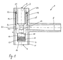
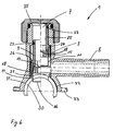
- a pipe tapping fitting 1 is shown half-cut.
- the Pipe tapping fitting 1 is essentially a pipe fitting with three Exits and with internals.
- the pipe tapping fitting 1 comprises a housing 2, which has a drill socket 3 which is perpendicular to the pipe axis media-promoting tube can be attached.
- the media-promoting pipe is not shown here and can promote gas, water or another medium.
- the pipe tapping fitting 1 is used for a branching pipeline, for example a connection line for a house from a main line, for example to branch off a supply line in the street underground.
- the connection process can be carried out without interruption the promotion of the medium that is promoted in the main management and without a loss of the medium.
- gas or Chemical delivery lines it is important for environmental reasons, to be able to work without losing the medium if possible.
- the drill socket 3 has a connection area 5 at a lower end 4 with which the drill socket 3 is connected to the pipe, not shown can be.
- the connection of the drill socket 3 with the pipe can for example with a pipe clamp, with plastic pipes with one electro-weldable saddle part or with another known Connection methods are made.
- an operating opening 7 is shown at the upper end 6 of the drill socket 3 .
- the operating opening 7 serves as Access for a tool that is used to connect the pipe tapping fitting 1 must be inserted into the main pipe in the drill socket 3.
- a branch pipe 8 is arranged at an angle to the drill pipe 3.
- the branch pipe 8 approximately at right angles to the drill pipe 3 arranged. However, depending on the conditions at the installation location, they are also angles larger or smaller than 90 ° conceivable. This ensures that the Connection line that must be connected to the branch connector 8 can be connected to the main line if possible without diversion.
- the Connection cable which was also not shown here, can be used with the same Connection method as described above with the branch pipe 8 get connected.
- the pipe tapping fitting 1 is in one state shown how the valve is delivered ready for installation on site becomes.
- a cutting sleeve 9 is shown as an installation in the drill socket 3.
- the Cutting sleeve 9 is essentially a cylindrical component that is concentric is arranged in the drill socket 3.
- the cutting sleeve 9 comprises from below up four areas: a cutting area 10, which as a core drill or a cutting sleeve 11 is formed, a drive region 12 in which a Tool for actuating the cutting sleeve 9 can be included, a Threaded area 13 with which the cutting sleeve 9 axially and radially in the Drill neck 3 is movable and a spatially from the threaded region 13th separate sealing area 19 which the cutting sleeve 9 to the drill socket 3 of the Seals housing 2.
- the drive area 12 has a tool holder 14 on the inside.
- the tool holder 14 is designed in such a way that a tool can be passed through the Operating opening 7 is inserted into the drill neck 3 from the Tool holder 14 is enclosed.
- the tool can be a normal one Allen key or a special tool. With this tool the cutting sleeve 9 is screwed in or out with respect to the drill socket 3, as is the case with a core drill.
- the drive area 12 can also be a Have end plate 15, with which the medium is prevented from the Main line can flow in the area of the control opening 7.
- the Operating opening 7 can also be closed with a Screw cap or an end cap, which is shown in Figure 6.
- the cutting sleeve 11 is made of a material that is suitable for the wall of the media-promoting pipe. Made of plastic pipes Polyethylene or polypropylene is sufficient with a cylindrical brass sleeve 11 ground cutting edge 16. Only the cutting area 10 is made of metal manufactured. The remaining areas of the cutting sleeve 9 can be the same Plastic material such as the housing 2 or from a compatible one Plastic material are made. If a heavier version if desired, the entire cutting sleeve 9 can also be made of the same Material, such as brass, are made. The cutting area 10 is as thin-walled as possible and takes that on the inside Plastic part on that from the wall of the media-promoting pipe was cut out.
- the cutting sleeve 11 has on the inside Special thread 17, which is used when drilling the pipe Take out cut plastic part in the cutting sleeve 11. With the Special thread 17 is further prevented that when unscrewing the pipe cut plastic part within the cutting sleeve 9 in one Inclined position tilts or even falls back from the cutting sleeve 9 into the tube.
- the threaded area 13, like the cutting sleeve 11, is cylindrical, but not necessarily made of metal or brass. With the threaded area 13 the cutting sleeve 9 is rotatably and operably arranged in the drill neck 3.
- the threaded area 13 of the cutting sleeve 9 has on the outside External thread 18 and a sealing area 19 on the inside.
- the Drill neck 3 has an internal thread 20 which is complementary to External thread 18 of the cutting sleeve 9 is formed.
- the drill socket 9 has a annular receiving pocket 21 on both the entire sealing area 19th as well as the complementary threads 18, 20 for the most part.
- annular design of the receiving pocket 21 ensures that both the Sealing area 19 as well as the complementary threads 18, 20 at the narrowest Space can be arranged. This will increase the overall height of the Pipe tapping fitting 1 kept as small as possible.
- the sealing area 19 of the cutting sleeve 9 has an annular groove 22 Inclusion of a sealant 23.
- the sealant is for example an O-ring seal 23, which is available in many standard sizes.
- the ring groove 22 is arranged in the cylindrical sealing region 19, which is spatially separated of the complementary threads 18, 20 formed on the cutting sleeve 9 is. Due to the spatially separate arrangement of the sealing area 19 and Threads 18, 20 become simple to manufacture and material-saving Sizing of the cutting sleeve possible.
- the wall parts, the sealing functions have to be designed for this task and on the other hand, the wall parts which have the threads 18, 20 can be exactly for that task can be interpreted.
- the inner wall of the cutting sleeve 9 and closer to the Center axis of the drill socket 3 lying wall of the receiving pocket 21 as possible can be formed smooth and uniform. This will make one possible good sealing effect between the drill socket 3 and the cutting sleeve 9 is achieved, so that the pipe tapping fitting 1 can also be used for high media pressures.
- the formation of the annular receiving pocket 21 of the drill socket 3 with the Internal thread 20 can be simplified by manufacturing the Drill neck 3 in two parts. By manufacturing in individual parts, the Inside of the receiving pocket can be processed or deformed more easily and the individual parts can then be glued, welded or Screwed together to form an annular receiving pocket 21 become.
- the annular grooves 22 and the O-ring seals 23 can instead of on Sealing area 19 of the cutting sleeve 9, also on the opposite Wall areas of the drill socket 3 of the housing 2 may be formed.
- the sealant 23 is arranged on a diameter that is essential is smaller than the diameter of the complementary threads 18, 20. As a result the sealing effect of the fitting 1 is further improved, since with a smaller one Diameter the forces occurring at the sealant 23 become smaller.
- the largest diameter, i.e. the Outer diameter of the O-ring seal 23 is smaller than the smallest Diameter, i.e. the inside diameter of the complementary threads 18, 20. Because the complementary threads 18, 20 compared to the O-ring seal 23 the operation will also have a relatively large diameter the cutting sleeve 9 much easier. The feed of the cutting sleeve 9 becomes, at the same pitch angle, proportional to the diameter of the complementary threads 18, 20 larger per revolution.
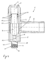
- FIGS Pipe tapping fitting 1 A second exemplary embodiment is shown in FIGS Pipe tapping fitting 1 according to the invention is shown.
- the cutting sleeve 9 has a different design than in Figures 1 and 2.
- the sealing area 19 is also spatially separated from the complementary threads 18, 20 arranged. The spatial separation is even more pronounced here than in the figures 1 and 2.
- the cutting sleeve 9 then points to the outer one Thread 18, which on a first wall region 24 of the cutting sleeve 9th is formed, a second wall area 25, which has a shoulder is connected to the first wall area 24.
- the sealant 23 is on this second wall region 25 of the cutting sleeve 9.
- the Sealant 23 is also arranged on a circle, with a Outside diameter that is smaller than the inside diameter of the Sealing area 19.
- the embodiment of Figures 3 to 5 stands out by good guidance of the cutting sleeve 9 when screwing in and out.
- the sealing effect can be further increased by a second O-ring seal 23 in a second annular groove 22 in the sealing area 19 of the cutting sleeve 9 correct dimensioning of the length ratios of the sealing area 19 and the complementary thread 18, 20 and by the arrangement of the annular grooves 22nd With the O-ring seals 23 at the right height, the overall height can be reduced to one Minimum be limited.
- a further pipe tapping fitting is connected to a media-promoting tube 30 shown.
- the Cutting sleeve 9 shown in a state in which the cutting sleeve 9 the media-promoting tube 30 has completely cut.
- the right half of Figure 6 shows the cutting sleeve 9 in a state in which the Cutting sleeve 9 the passage of the media-conveying pipe in the Branch connector 8 releases completely.
- the tapping fitting 1 from FIG. 6 can be opened different types are connected to the media-promoting tube 30, In Figure 6 this is indicated by an adhesive 31, by a Electrical welding connection 32 and through a pipe clamp half 33.
- Die Cutting sleeve 9 is in the manufacture from below into the pipe tapping fitting 1st screwed in to the state of the right half of Figure 6. Then will a substantially ring-shaped insert 34 also from below in the Drill neck 3 introduced.
- the insert 34 can at the lower end of the Boring socket 3 are glued, welded or screwed in. With the Insert 34 is prevented that when drilling the pipe 30 Cutting sleeve 9 is screwed too deep into the tube 30. If the Cutting sleeve 9 would be screwed too deep into the tube 30, would at the top End of the cutting sleeve 9 no more sealing effect would be guaranteed the medium escape from the pipe 30 during the tapping process.
- the thread 18 can be cut out or the length of the thread 18 can be so short be chosen that the high torque required for the cutting process is only transmitted up to a defined position. This ensures that the cutting sleeve 9 no longer has any torque below this defined position transmits and slips into space, so to speak.
- a screw cap 35 or an end cover At the upper end of the drill neck 3 in the area of the operating opening 7 also shown a screw cap 35 or an end cover. With the Screw cap 35 becomes the tapping fitting 1 after the tapping process additionally closed.
- the tapping fitting 1 is used wherever a Loss of the medium is undesirable or pose a danger to the environment can.
Landscapes
- Engineering & Computer Science (AREA)
- General Engineering & Computer Science (AREA)
- Mechanical Engineering (AREA)
- Branch Pipes, Bends, And The Like (AREA)
- Drilling And Boring (AREA)
- Drilling Tools (AREA)
- Earth Drilling (AREA)
- Perforating, Stamping-Out Or Severing By Means Other Than Cutting (AREA)
Abstract
Description
Die Erfindung bezieht sich auf eine Rohranbohrarmatur für ein medienförderndes Rohr, umfassend ein Gehäuse, das einen unter einem Winkel zur Rohrachse anbringbaren Bohrstutzen zum Anbohren der Rohrwand und einen unter einem Winkel zum Bohrstutzen angeordneten Abzweigstutzen aufweist, wobei im Bohrstutzen eine drehbetätigbare Schneidbüchse angeordnet ist, wobei die Schneidbüchse und der Bohrstutzen zueinander komplementäre Gewinde aufweisen und wobei zwischen Bohrstutzen und Schneidbüchse mindestens ein Dichtungsmittel zur Abdichtung des medienfördernden Rohres gegen Aussen vorgesehen ist.The invention relates to a pipe tapping fitting for a media-promoting A tube comprising a housing which is at an angle to the tube axis attachable drill nozzle for drilling the pipe wall and one under one Has angle to the drill nozzle arranged branch connector, wherein in Drill socket a rotatably actuated cutting sleeve is arranged, the Cutting sleeve and the drill socket complementary thread have and wherein at least one between the drill socket and the cutting sleeve Sealant to seal the media-conveying pipe from the outside is provided.
Aus der DE 196 30 029 A1 ist eine Rohranbohrarmatur bekannt, wobei die Schneidbüchse sowohl eine Schneidfunktion als auch eine Dichtfunktion hat. Die Dichtfunktion wird erreicht durch elastische Dichtringe, die in Radialnuten auf der Aussenseite der Schneidbüchse im Bereich eines Aussengewindeganges angeordnet sind und einem komplementären Innengewindegang des Bohrstutzens entlang gleiten. Der Innengewindegang erstreckt sich über eine Länge, die ein Vielfaches länger ist als die Dicke des Dichtringes. Auf dieser Länge kann der elastische Dichtring vom Innengewinde bei einem wiederholten Ein- und Ausschrauben leicht angeschnitten und beschädigt werden. Die grosse Länge führt auch zu einer grossen Bauhöhe.A pipe tapping fitting is known from DE 196 30 029 A1, the Cutting sleeve has both a cutting function and a sealing function. The Sealing function is achieved by elastic sealing rings, which are in radial grooves on the Outside of the cutting sleeve in the area of an external thread are arranged and a complementary internal thread of the drill socket slide along. The internal thread extends over a length that a Is many times longer than the thickness of the sealing ring. On this length the elastic sealing ring from the internal thread with repeated insertion and Unscrew easily cut and damaged. The great length also leads to a large overall height.
Ausgehend von diesem Stand der Technik ist es Aufgabe der Erfindung, eine Rohranbohrarmatur anzugeben, die möglichst einfach und kompakt aufgebaut ist und in allen Phasen der Anwendung eine möglichst gute Dichtfunktion hat.Based on this prior art, it is an object of the invention to Specify pipe tapping fitting that is as simple and compact as possible and has the best possible sealing function in all phases of the application.
Diese Aufgabe wird gelöst durch eine Rohranbohrarmatur mit den Merkmalen des Patentanspruchs 1.This object is achieved by a pipe tapping fitting with the features of Claim 1.
Bevorzugte Weiterbildungen der Erfindung ergeben sich aus den abhängigen Patentansprüchen.Preferred developments of the invention result from the dependent ones Claims.
Es ist von Vorteil, dass die Rohranbohrarmatur einen möglichst hohen Druck des Fördermittels aushalten kann. Dies wird dadurch erreicht, dass das Dichtungsmittel zwischen Bohrstutzen und Schneidbüchse radial nach innen und beabstandet von den komplementären Gewinden angeordnet ist. Die Kraft, die auf das elastische Dichtungsmittel wirkt, nimmt zu mit dem Durchmesser des Dichtungsmittels.It is advantageous that the pipe tapping valve has the highest possible pressure Funds can withstand. This is achieved in that the Sealant between the drill socket and the cutting sleeve radially inwards and spaced from the complementary threads. The force on the elastic sealant acts, increases with the diameter of the Sealant.
Es ist auch von Vorteil, dass die Rohranbohrarmatur möglichst einfach hergestellt werden kann. Dies wird dadurch erreicht, dass das Dichtungsmittel zwischen dem Bohrstutzen des Gehäuses und der Schneidbüchse in einem einförmigen und vom Gewinde beabstandeten Dichtungsbereich der Schneidbüchse angeordnet ist. Dies wird auch dadurch erreicht, dass der Dichtungsbereich an einer Innenwand der Schneidbüchse ausgebildet ist und dass das Gewinde als Aussengewinde an einer Aussenwand der Schneidbüchse ausgebildet ist. Durch die Zuordnung der Funktionen Schneiden, Dichten, Befestigen und Antreiben zu räumlich getrennten Bereichen wird erreicht, dass die Dimensionierung der Schneidbüchse optimal auf der jeweiligen Funktion der unterschiedlichen Bereiche ausgerichtet werden kann.It is also advantageous that the pipe tapping fitting is manufactured as simply as possible can be. This is achieved in that the sealant between the Drill neck of the housing and the cutting sleeve in a uniform and from Thread spaced sealing area of the cutting sleeve is arranged. This is also achieved in that the sealing area on an inner wall the cutting sleeve is designed and that the thread as an external thread an outer wall of the cutting sleeve is formed. By assigning the Functions cutting, sealing, fastening and driving to spatially separated Areas is achieved that the dimensioning of the cutting sleeve is optimal can be aligned with the respective function of the different areas.
Es ist weiter von Vorteil, dass die Rohranbohrarmatur eine möglichst niedrige Bauhöhe aufweist. Dies wird dadurch erreicht, dass der Bohrstutzen eine ringförmige Aufnahmetasche zur Aufnahme des Dichtungsbereichs und des Gewindebereichs aufweist. Die Bauhöhe der Rohranbohrarmatur bleibt trotz der Zufügung des Dichtungsbereichs gleich gross oder kleiner als bei bestehenden Armaturen.It is also advantageous that the pipe tapping fitting is as low as possible Has overall height. This is achieved in that the drill socket is a annular receiving pocket for receiving the sealing area and the Has thread area. The overall height of the pipe tapping valve remains despite Add the sealing area the same size or smaller than existing ones Fittings.
Ausführungsbeispiele der Erfindung werden anhand der Figuren beschrieben.
Es zeigen:
In Figur 1 ist eine Rohranbohrarmatur 1 halbgeschnitten dargestellt. Die
Rohranbohrarmatur 1 ist im Wesentlichen eine Rohrleitungsarmatur mit drei
Ausgängen und mit Einbauten. Die Rohranbohrarmatur 1 umfasst ein Gehäuse 2,
das einen Bohrstutzen 3 aufweist, der senkrecht zur Rohrachse eines
medienfördernden Rohres angebracht werden kann. Das medienfördernde Rohr
ist hier nicht dargestellt und kann Gas, Wasser oder ein anderes Medium fördern.
Die Rohranbohrarmatur 1 dient dazu, eine abzweigende Rohrleitung,
beispielsweise eine Anschlussleitung für ein Haus von einer Hauptleitung,
beispielsweise eine Versorgungsleitung in dem Strassenuntergrund abzuzweigen.
Mit der Rohranbohrarmatur 1 kann der Anschlussvorgang ohne Unterbrechung
der Förderung des Mediums, dass in der Hauptleitung gefördert wird und ohne
einen Verlust des Mediums durchgeführt werden. Vor allem bei Gas- oder
Chemikalienförderleitungen ist es aus Gründen des Umweltschutzes wichtig,
möglichst ohne Verlust des Mediums arbeiten zu können. In Figure 1, a pipe tapping fitting 1 is shown half-cut. The
Pipe tapping fitting 1 is essentially a pipe fitting with three
Exits and with internals. The pipe tapping fitting 1 comprises a
Der Bohrstutzen 3 weist an einem unteren Ende 4 einen Verbindungsbereich 5
auf, mit dem der Bohrstutzen 3 mit dem nicht dargestellten Rohr verbunden
werden kann. Die Verbindung des Bohrstutzens 3 mit dem Rohr kann
beispielsweise mit einer Rohrschelle, bei Kunststoffrohren mit einem
elektroschweissbaren Sattelteil oder mit einem anderen bekannten
Verbindungsverfahren hergestellt werden. Am oberen Ende 6 des Bohrstutzens 3
ist eine Bedienungsöffnung 7 dargestellt. Die Bedienungsöffnung 7 dient als
Zugang für ein Werkzeug, das für den Anschlussvorgang der Rohranbohrarmatur
1 an die Hauptleitung in den Bohrstutzen 3 eingeführt werden muss.The
Unter einem Winkel zum Bohrstutzen 3 ist ein Abzweigstutzen 8 angeordnet. In
Figur 1 ist der Abzweigstutzen 8 etwa rechtwinklig zu dem Bohrstutzen 3
angeordnet. Es sind jedoch auch, je nach den Bedingungen am Einbauort, Winkel
grösser oder kleiner als 90° denkbar. Hiermit wird erreicht, dass die
Anschlussleitung, die mit dem Abzweigstutzen 8 verbunden werden muss,
möglichst ohne Umleitung an der Hauptleitung angeschlossen werden kann. Die
Anschlussleitung, die hier ebenfalls nicht dargestellt wurde, kann mit den gleichen
Verbindungsverfahren wie oben beschrieben mit dem Abzweigstutzen 8
verbunden werden. In Figur 1 ist die Rohranbohrarmatur 1 in einem Zustand
dargestellt, wie die Armatur zum Einbau vorbereitet auf der Baustelle angeliefert
wird.A
Als Einbau im Bohrstutzen 3 ist eine Schneidbüchse 9 dargestellt. Die
Schneidbüchse 9 ist im Wesentlichen ein zylindrisches Bauteil, das konzentrisch
in dem Bohrstutzen 3 angeordnet ist. Die Schneidbüchse 9 umfasst von unten
nach oben vier Bereiche: einen Schneidbereich 10, der als einen Kernbohrer oder
eine Schneidhülse 11 ausgebildet ist, einen Antriebsbereich 12, in der ein
Werkzeug zur Betätigung der Schneidbüchse 9 aufgenommen werden kann, einen
Gewindebereich 13, mit der die Schneidbüchse 9 axial und radial in dem
Bohrstutzen 3 bewegbar ist und einen räumlich vom Gewindebereich 13
getrennten Dichtungsbereich 19, der die Schneidbüchse 9 zum Bohrstutzen 3 des
Gehäuses 2 abdichtet.A
Der Antriebsbereich 12 weist auf der Innenseite eine Werkzeugaufnahme 14 auf.
Die Werkzeugaufnahme 14 ist so ausgebildet, dass ein Werkzeug, dass durch die
Bedienungsöffnung 7 in den Bohrstutzen 3 eingeführt wird von der
Werkzeugaufnahme 14 umschlossen wird. Das Werkzeug kann ein normaler
Innensechskantschlüssel oder ein Spezialwerkzeug sein. Mit diesem Werkzeug
wird die Schneidbüchse 9 gegenüber dem Bohrstutzen 3 ein- oder ausgeschraubt,
wie das bei einem Kernbohrer der Fall ist. Der Antriebsbereich 12 kann auch eine
Abschlussplatte 15 aufweisen, mit der verhindert wird, dass das Medium aus der
Hauptleitung im Bereich der Bedienungsöffnung 7 fliessen kann. Die
Bedienungsöffnung 7 kann zusätzlich verschlossen werden mit einer
Schraubkappe oder einen Abschlussdeckel, der in Figur 6 dargestellt ist.The
Die Schneidhülse 11 ist aus einem Material hergestellt, das geeignet ist, die Wand
des medienfördernden Rohres zu durchtrennen. Für Kunststoffrohre aus
Polyäthylen oder Polypropylen genügt eine zylindrische Messinghülse 11 mit einer
geschliffenen Schneidkante 16. Nur der Schneidbereich 10 ist aus Metall
hergestellt. Die übrigen Bereiche der Schneidbüchse 9 können aus dem gleichen
Kunststoffmaterial wie das Gehäuse 2 oder aus einem damit kompatiblen
Kunststoffmaterial hergestellt werden. Wenn eine schwerere Ausführung
gewünscht wird, kann auch die gesamte Schneidbüchse 9 aus demselben
Material, beispielsweise Messing, hergestellt werden. Der Schneidbereich 10 ist
so dünnwandig wie möglich ausgebildet und nimmt auf der Innenseite das
Kunststoffteil auf, das aus der Wand des medienfördernden Rohres
ausgeschnitten wurde. Die Schneidhülse 11 weist auf der Innenseite ein
Spezialgewinde 17 auf, das dazu dient, beim Anbohren des Rohres das
ausgeschnittene Kunststoffteil in die Schneidhülse 11 aufzunehmen. Mit dem
Spezialgewinde 17 wird weiterhin verhindert, dass, beim Ausschrauben das aus
dem Rohr ausgeschnittene Kunststoffteil innerhalb der Schneidbüchse 9 in einer
Schräglage kippt oder sogar aus der Schneidbüchse 9 in das Rohr zurückfällt.The
Der Gewindebereich 13 ist wie die Schneidhülse 11 zylindrisch ausgebildet,
jedoch nicht zwingend aus Metall oder Messing. Mit dem Gewindebereich 13 wird
die Schneidbüchse 9 drehbar und betätigbar in dem Bohrstutzen 3 angeordnet.
Der Gewindebereich 13 der Schneidbüchse 9 weist auf der Aussenseite ein
Aussengewinde 18 und auf der Innenseite einen Dichtungsbereich 19 auf. Der
Bohrstutzen 3 weist ein Innengewinde 20 auf, der komplementär zum
Aussengewinde 18 der Schneidbüchse 9 ausgebildet ist.The threaded
In dem Ausführungsbeispiel von Figur 1 und 2 weist der Bohrstutzen 9 eine
ringförmige Aufnahmetasche 21 auf, der sowohl der gesamte Dichtungsbereich 19
als auch die komplementären Gewinde 18, 20 grösstenteils aufnimmt. Durch die
ringförmige Ausbildung der Aufnahmetasche 21 wird erreicht, dass sowohl der
Dichtungsbereich 19 als auch die komplementären Gewinde 18, 20 auf engstem
Raum angeordnet werden kann. Hierdurch wird die Bauhöhe der
Rohranbohrarmatur 1 so klein wie möglich gehalten.In the embodiment of Figures 1 and 2, the
Der Dichtungsbereich 19 der Schneidbüchse 9 weist eine Ringnut 22 zur
Aufnahme eines Dichtungsmittels 23 auf. Das Dichtungsmittel ist beispielsweise
eine O-Ringdichtung 23, die in vielen Standardgrössen erhältlich ist. Die Ringnut
22 ist in dem zylindrischen Dichtungsbereich 19 angeordnet, der räumlich getrennt
von den komplementären Gewinden 18, 20 an der Schneidbüchse 9 ausgebildet
ist. Durch die räumlich getrennte Anordnung des Dichtungsbereiches 19 und der
Gewinde 18, 20 wird eine einfache Herstellung und eine materialsparende
Dimensionierung der Schneidbüchse möglich. Einerseits können die Wandteile,
die Dichtungsfunktionen haben genau für diese Aufgabe ausgelegt werden und
andererseits können die Wandteile, die die Gewinde 18, 20 aufweisen, genau für
jene Aufgabe ausgelegt werden. In der Herstellung bedeutet dies, dass im Beispiel
von Figur 1 und 2 die Innenwand der Schneidbüchse 9 und die näher bei der
Mittelachse des Bohrstutzens 3 liegende Wand der Aufnahmetasche 21 möglichst
glatt und einförmig ausgebildet werden können. Hierdurch wird eine möglichst
gute Dichtwirkung zwischen Bohrstutzen 3 und Schneidbüchse 9 erreicht, so dass
die Rohranbohrarmatur 1 auch für hohe Mediendrücke eingesetzt werden kann.
Die Ausbildung der ringförmigen Aufnahmetasche 21 des Bohrstutzens 3 mit dem
Innengewinde 20 kann vereinfacht werden durch eine Herstellung des
Bohrstutzens 3 in zwei Einzelteilen. Durch die Herstellung in Einzelteilen kann die
Innenseite der Aufnahmetasche leichter bearbeitet oder verformt werden und
anschliessend können die Einzelteile durch Verklebung, Verschweissung oder
Verschraubung zu einer ringförmigen Aufnahmetasche 21 zusammengefügt
werden. Die Ringnuten 22 und die O-Ringdichtungen 23 können, statt an dem
Dichtungsbereich 19 der Schneidbüchse 9, auch an den gegenüberliegenden
Wandbereichen des Bohrstutzens 3 des Gehäuses 2 ausgebildet sein.The sealing
Das Dichtungsmittel 23 ist auf einem Durchmesser angeordnet, der wesentlich
kleiner ist als der Durchmesser der komplementären Gewinde 18, 20. Hierdurch
wird die Dichtwirkung der Armatur 1 nochmals verbessert, da mit kleinerem
Durchmesser die an dem Dichtungsmittel 23 auftretenden Kräfte geringer werden.
In den Figuren 1 und 2 ist ersichtlich, dass der grösste Durchmesser, d.h. der
Aussendurchmesser der O-Ringdichtung 23 kleiner ist als der kleinste
Durchmesser, d.h. der Innendurchmesser der komplementären Gewinde 18, 20.
Weil die komplementäre Gewinde 18, 20 im Vergleich zu der O-Ringdichtung 23
einen verhältnismässig grossen Durchmesser aufweisen, wird auch die Bedienung
der Schneidbüchse 9 wesentlich erleichtert. Der Vorschub der Schneidbüchse 9
wird, bei gleichem Steigungswinkel, proportional zum Durchmesser der
komplementären Gewinde 18, 20 pro Umdrehung grösser.The
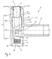
In Figur 2 ist die Rohranbohrarmatur 1 von Figur 1 nochmals geschnitten
dargestellt, hier jedoch in der Stellung nach dem vollständigen Einschrauben der
Schneidbüchse 9 in die Wand des medienfördernden Rohres. In dieser Stellung
wurde das Rohr bereits angebohrt und ein Teil der Rohrwand wurde dabei in der
Schneidhülse 10 aufgenommen. Ein zu tief gehendes Einschrauben kann durch
einen Anschlag verhindert werden. Es ist ersichtlich, wie auch in der
eingeschraubten Stellung die Schneidbüchse 9 noch von der Aufnahmetasche 21
des Bohrstutzen 3 geführt und abgedichtet wird. Als nächster Schritt wird,
ausgehend von dieser Stellung, die Schneidbüchse 9 wieder ausgeschraubt bis
zur Stellung von Figur 1. Das Werkzeug zur Betätigung der Schneidbüchse 9 kann
aus der Bedienungsöffnung 7 herausgenommen werden. Als zusätzliche Dichtung
und zur Sicherung der Anordnung gegen unerwünschten Zugriffen kann die
Bedienungsöffnung 7 mit einer in Figur 6 dargestellten Abschlusskappe oder mit
einem Schraubdeckel verschlossen werden.In Figure 2, the pipe tapping fitting 1 of Figure 1 is cut again
shown, but here in the position after the screwing in
In den Figuren 3 bis 5 ist ein zweites Ausführungsbeispiel der
erfindungsgemässen Rohranbohrarmatur 1 dargestellt. Die Schneidbüchse 9 weist
eine andere Ausführung als in den Figuren 1 und 2 auf. Der Dichtungsbereich 19
ist auch hier räumlich getrennt von den komplementären Gewinden 18, 20
angeordnet. Die räumliche Trennung ist hier noch ausgeprägter als in den Figuren
1 und 2. Die Schneidbüchse 9 weist hier anschliessend an dem äusseren
Gewinde 18, der an einem ersten Wandbereich 24 der Schneidbüchse 9
ausgebildet ist, noch einen zweiten Wandbereich 25 auf, der über einen Absatz
mit dem ersten Wandbereich 24 verbunden ist. Das Dichtungsmittel 23 ist an
diesem zweiten Wandbereich 25 der Schneidbüchse 9 ausgebildet. Das
Dichtungsmittel 23 ist ebenfalls auf einem Kreis angeordnet, mit einem
Aussendurchmesser, der kleiner ist als der Innendurchmesser des
Dichtungsbereichs 19. Das Ausführungsbeispiel von Figuren 3 bis 5 zeichnet sich
aus durch eine gute Führung der Schneidbüchse 9 beim Ein- und Ausschrauben.A second exemplary embodiment is shown in FIGS
Pipe tapping fitting 1 according to the invention is shown. The cutting
Die Dichtwirkung kann weiter erhöht werden durch eine zweite O-Ringdichtung 23
in einer zweiten Ringnut 22 im Dichtungsbereich 19 der Schneidbüchse 9. Bei der
richtigen Dimensionierung der Längenverhältnisse des Dichtungsbereiches 19 und
der komplementären Gewinde 18, 20 und durch die Anordnung der Ringnuten 22
mit den O-Ringdichtungen 23 in der richtigen Höhe kann die Bauhöhe auf ein
Minimum beschränkt werden. The sealing effect can be further increased by a second O-
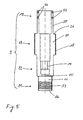
In Figur 5 ist die Schneidbüchse 9 aus Figuren 3 und 4 alleine dargestellt. Hier
sind die einzelnen Bereichen der Schneidbüchse 9 deutlich zu erkennen. Von
unten nach oben die Schneidhülse 11, der Antriebsbereich 12 mit der
Werkzeugaufnahme 14, der Gewindebereich 13 mit dem Aussengewinde und der
Dichtungsbereich 19 mit den Ringnuten 22 und den O-Ringdichtungen 23.In Figure 5, the cutting
In Figur 6 ist eine weitere Rohranbohrarmatur verbunden mit einem
medienfördernden Rohr 30 dargestellt. In der linken Hälfte von Figur 6 ist die
Schneidbüchse 9 in einem Zustand dargestellt, bei der die Schneidbüchse 9 das
medienfördernde Rohr 30 vollständig durchtrennt hat. In der rechten Hälfte von
Figur 6 ist die Schneidbüchse 9 in einem Zustand dargestellt, bei der die
Schneidbüchse 9 den Durchgang von dem medienfördernden Rohr in dem
Abzweigstutzen 8 vollständig freigibt. Die Anbohrarmatur 1 von Figur 6 kann auf
unterschiedlicher Art mit dem medienfördernden Rohr 30 verbunden werden, In
Figur 6 ist dies angedeutet durch eine Verklebung 31, durch eine
Elektroschweissverbindung 32 und durch eine Rohrschellenhälfte 33. Die
Schneidbüchse 9 wird bei der Herstellung von unten in die Rohranbohrarmatur 1
bis zum Zustand der rechten Hälfte von Figur 6 eingeschraubt. Anschliessend wird
ein im Wesentlichen ringförmiges Einsatzteil 34 ebenfalls von unten in den
Bohrstutzen 3 eingebracht. Das Einsatzteil 34 kann am unteren Ende des
Bohrstutzens 3 eingeklebt, eingeschweisst oder eingeschraubt werden. Mit dem
Einsatzteil 34 wird verhindert, dass beim Anbohren des Rohres 30 die
Schneidbüchse 9 zu tief in das Rohr 30 eingeschraubt wird. Wenn die
Schneidbüchse 9 zu tief in das Rohr 30 eingeschraubt würde, würde am oberen
Ende der Schneidbüchse 9 keine Dichtwirkung mehr gewährleistet sein und würde
das Medium beim Anbohrvorgang aus dem Rohr 30 entweichen. Ein zu tiefes
Einschrauben kann jedoch auch verhindert werden durch eine besondere
Ausbildung des Gewindes 18 im unteren Bereich. Das Gewinde 18 kann
auslaufend geschnitten werden oder die Länge des Gewindes 18 kann so kurz
gewählt werden, dass das hohe Drehmoment, das für den Schneidvorgang nötig
ist, nur bis zu einer definierten Position übertragen wird. Hiermit wird erreicht, dass
die Schneidbüchse 9 unterhalb dieser definierten Position kein Drehmoment mehr
überträgt und sozusagen ins Leere rutscht.In Figure 6, a further pipe tapping fitting is connected to a
media-promoting
Am oberen Ende des Bohrstutzens 3 im Bereich der Bedienungsöffnung 7 ist
ebenfalls eine Schraubkappe 35 oder einen Abschlussdeckel dargestellt. Mit der
Schraubkappe 35 wird die Anbohrarmatur 1 nach erfolgtem Anbohrvorgang
zusätzlich verschlossen. Die Anbohrarmatur 1 wird überall dort eingesetzt, wo ein
Verlust des Mediums unerwünscht ist oder eine Gefahr für die Umwelt bedeuten
kann.At the upper end of the
Claims (7)
Applications Claiming Priority (2)
| Application Number | Priority Date | Filing Date | Title |
|---|---|---|---|
| DE19932401 | 1999-07-14 | ||
| DE19932401.8A DE19932401B4 (en) | 1999-07-14 | 1999-07-14 | Rohranbohrarmatur |
Publications (2)
| Publication Number | Publication Date |
|---|---|
| EP1069367A1 true EP1069367A1 (en) | 2001-01-17 |
| EP1069367B1 EP1069367B1 (en) | 2011-08-17 |
Family
ID=7914413
Family Applications (1)
| Application Number | Title | Priority Date | Filing Date |
|---|---|---|---|
| EP20000108580 Revoked EP1069367B1 (en) | 1999-07-14 | 2000-04-20 | Tapping fitting for pipes |
Country Status (6)
| Country | Link |
|---|---|
| US (1) | US6260573B1 (en) |
| EP (1) | EP1069367B1 (en) |
| JP (1) | JP4545288B2 (en) |
| AT (1) | ATE520921T1 (en) |
| BR (1) | BR0002724A (en) |
| DE (1) | DE19932401B4 (en) |
Cited By (1)
| Publication number | Priority date | Publication date | Assignee | Title |
|---|---|---|---|---|
| WO2011100383A1 (en) | 2010-02-12 | 2011-08-18 | Elster Perfection Corporation | Cutter assembly |
Families Citing this family (9)
| Publication number | Priority date | Publication date | Assignee | Title |
|---|---|---|---|---|
| US6612330B1 (en) * | 2000-07-06 | 2003-09-02 | Keyspan Corporation | No interrupt service tee and method |
| GB2369662A (en) * | 2000-11-29 | 2002-06-05 | Uponor Ltd | Tapping fitting for use with a plastics pipe |
| PT1331429E (en) * | 2002-01-12 | 2004-10-29 | Agru Kunststofftechnik Gmbh | DEVICE FOR THE EXECUTION OF EXPLORATION HOLES OF CANALIZACOES |
| WO2003106880A1 (en) * | 2002-06-12 | 2003-12-24 | Marcelo Hombravella Abbad | Device for producing bypasses under pressure in fluid piping systems |
| DE10310171B4 (en) * | 2003-01-24 | 2006-09-07 | Friatec Ag | Tapping Bridge |
| GB2421553A (en) * | 2004-12-23 | 2006-06-28 | Uponor Innovation Ab | Tapping tee assembly with an integrated cutter and dual electrofusion elements |
| DE102015122731B3 (en) | 2015-12-23 | 2016-12-22 | Friatec Aktiengesellschaft | Tapping fitting and a corresponding manufacturing process |
| DK3366969T3 (en) | 2017-02-28 | 2022-08-15 | Georg Fischer Wavin Ag | PIPE DRILLING FITTING |
| KR102229571B1 (en) * | 2020-09-03 | 2021-03-18 | (주) 폴리텍 | Branch joint pipe |
Citations (4)
| Publication number | Priority date | Publication date | Assignee | Title |
|---|---|---|---|---|
| US3349792A (en) | 1965-02-24 | 1967-10-31 | Phillips Petroleum Co | Tapping t and valve |
| DE19543681A1 (en) * | 1994-11-28 | 1996-06-27 | Gawatec Rohrverbindungssysteme | Branch for house connecting line linked to supply line |
| EP0811799A2 (en) * | 1996-06-08 | 1997-12-10 | MANIBS Spezialarmaturen GmbH & Co. KG | Tapping device with valve for supply plastic pipes under pressure |
| DE19630029A1 (en) | 1996-07-25 | 1998-01-29 | Manibs Spezialarmaturen | Valve tapping fitting for plastics pipelines under pressure |
Family Cites Families (20)
| Publication number | Priority date | Publication date | Assignee | Title |
|---|---|---|---|---|
| US2839075A (en) * | 1954-02-16 | 1958-06-17 | Mueller Co | Service t for plastic mains |
| US3756261A (en) * | 1971-11-16 | 1973-09-04 | Amp Inc | Method and apparatus for connecting a tap to a pipeline |
| US4029118A (en) * | 1975-07-03 | 1977-06-14 | Phillips Petroleum Company | Tapping apparatus and method |
| US4076038A (en) * | 1976-01-05 | 1978-02-28 | Phillips Petroleum Company | Tapping tee cutter having relieved sidewall |
| JPS583991Y2 (en) * | 1977-03-25 | 1983-01-24 | 積水化学工業株式会社 | branch pipe fittings |
| US4258742A (en) * | 1979-04-03 | 1981-03-31 | Phillips Petroleum Company | Tapping apparatus |
| JPS6128994U (en) * | 1984-07-24 | 1986-02-21 | 三菱樹脂株式会社 | branch pipe fittings |
| EP0170844B1 (en) * | 1984-08-08 | 1988-01-20 | Georg Fischer Aktiengesellschaft | Shaped piercing piece consisting of weldable plastics |
| DE3723898A1 (en) * | 1987-07-18 | 1989-01-26 | Friedrichsfeld Gmbh | Boring fitting |
| DE3830395C1 (en) | 1988-09-07 | 1990-01-11 | Friedrichsfeld Gmbh Keramik- Und Kunststoffwerke, 6800 Mannheim, De | Boring fitting |
| US5076318A (en) * | 1990-08-23 | 1991-12-31 | Phillips Petroleum Company | Tapping tee cutter for plastic pipe |
| DE9115052U1 (en) * | 1991-12-04 | 1993-04-01 | Gebr. Rehbein, 42855 Remscheid | Milling cutter tapping fitting |
| DE4204620A1 (en) | 1992-02-15 | 1993-08-19 | Manibs Spezialarmaturen | PIPE CLAMP FOR PLASTIC SUPPLY PIPES, IN PARTICULAR TUBING CLAMP |
| DE4217982C2 (en) * | 1992-05-30 | 1994-06-30 | Friatec Keramik Kunststoff | Valve tapping valve |
| JP2562886Y2 (en) * | 1993-12-14 | 1998-02-16 | 東亜高級継手バルブ製造株式会社 | Plastic branch pipe fittings |
| DE4408817C1 (en) * | 1994-03-16 | 1995-06-22 | Ewe Wilhelm Gmbh & Co Kg | Valve/drilling fitting with integrated cut-off of operation |
| US5577529A (en) * | 1995-01-19 | 1996-11-26 | Plasson Maagan Michael Industries Ltd. | Tapping fittings |
| IL114505A (en) | 1995-07-09 | 1998-02-22 | Plasson Maagan Michael Ind Ltd | Tapping fitting |
| US5896885A (en) | 1996-06-11 | 1999-04-27 | Phillips Petroleum Company | Tapping saddle pipe fitting |
| IL122286A (en) * | 1996-11-30 | 2002-02-10 | Friatec Ag | Pipe tapping device |
-
1999
- 1999-07-14 DE DE19932401.8A patent/DE19932401B4/en not_active Expired - Lifetime
-
2000
- 2000-04-20 EP EP20000108580 patent/EP1069367B1/en not_active Revoked
- 2000-04-20 AT AT00108580T patent/ATE520921T1/en active
- 2000-06-19 JP JP2000183047A patent/JP4545288B2/en not_active Expired - Fee Related
- 2000-07-07 US US09/612,474 patent/US6260573B1/en not_active Expired - Fee Related
- 2000-07-12 BR BR0002724A patent/BR0002724A/en not_active IP Right Cessation
Patent Citations (4)
| Publication number | Priority date | Publication date | Assignee | Title |
|---|---|---|---|---|
| US3349792A (en) | 1965-02-24 | 1967-10-31 | Phillips Petroleum Co | Tapping t and valve |
| DE19543681A1 (en) * | 1994-11-28 | 1996-06-27 | Gawatec Rohrverbindungssysteme | Branch for house connecting line linked to supply line |
| EP0811799A2 (en) * | 1996-06-08 | 1997-12-10 | MANIBS Spezialarmaturen GmbH & Co. KG | Tapping device with valve for supply plastic pipes under pressure |
| DE19630029A1 (en) | 1996-07-25 | 1998-01-29 | Manibs Spezialarmaturen | Valve tapping fitting for plastics pipelines under pressure |
Cited By (3)
| Publication number | Priority date | Publication date | Assignee | Title |
|---|---|---|---|---|
| WO2011100383A1 (en) | 2010-02-12 | 2011-08-18 | Elster Perfection Corporation | Cutter assembly |
| EP2533925A4 (en) * | 2010-02-12 | 2012-12-19 | Elster Perfection Corp | Cutter assembly |
| US8826929B2 (en) | 2010-02-12 | 2014-09-09 | Elster Perfection Corporation | Cutter assembly |
Also Published As
| Publication number | Publication date |
|---|---|
| EP1069367B1 (en) | 2011-08-17 |
| BR0002724A (en) | 2001-03-13 |
| US6260573B1 (en) | 2001-07-17 |
| DE19932401A1 (en) | 2001-01-18 |
| JP4545288B2 (en) | 2010-09-15 |
| JP2001041384A (en) | 2001-02-13 |
| DE19932401B4 (en) | 2017-08-31 |
| ATE520921T1 (en) | 2011-09-15 |
Similar Documents
| Publication | Publication Date | Title |
|---|---|---|
| DE69212793T2 (en) | Connecting device for parts of a fluid distribution system, said parts and system | |
| EP1290371B1 (en) | Tapping stop valve | |
| DE3604194C2 (en) | Plugs for heat exchanger tubes or pipes | |
| EP0314123A2 (en) | Connector, especially for diamond core bit with tubular part and threaded connection | |
| DE3808674C2 (en) | Tapping valve | |
| EP0261326B1 (en) | Corner valve for building water mains | |
| DE19932401B4 (en) | Rohranbohrarmatur | |
| DE19531913C2 (en) | Combined tapping and valve tapping fitting for plastic supply lines, especially under media pressure | |
| DE3830395C1 (en) | Boring fitting | |
| DE60115413T2 (en) | FITTING FOR A PRESSURE COUPLING FOR PLASTIC PIPES | |
| EP0736718A1 (en) | Tapping apparatus for plastic conduits, especially under pressure | |
| EP0734499B1 (en) | Method of broaching a line and pipe broaching unit for carrying out the method | |
| DE10233863B4 (en) | Connection block for sanitary fittings | |
| EP0879377B1 (en) | Detachable pipe joint for plastic pipes | |
| EP1441168B1 (en) | Tapping device with valve | |
| DE2147026C3 (en) | Valve attachment | |
| DE102005008398B4 (en) | Tapping fitting for plastic pipes and method for connecting a tapping fitting | |
| DE69701488T2 (en) | Fluid valve | |
| EP3366969B1 (en) | Branch connecting device | |
| DE19750352C1 (en) | Branch drill assembly for fluid pipe | |
| DE19630028C2 (en) | Valve tapping fitting for plastic supply lines, preferably under media pressure | |
| DE69806921T2 (en) | SEAL FOR A BRANCH ON A GAS PIPE | |
| DE20004624U1 (en) | Wall connection fitting for fittings | |
| DE19630029A1 (en) | Valve tapping fitting for plastics pipelines under pressure | |
| DE4010177A1 (en) | Device for venting pipe line - has valve which can be opened by rotating screwed operating rod |
Legal Events
| Date | Code | Title | Description |
|---|---|---|---|
| PUAI | Public reference made under article 153(3) epc to a published international application that has entered the european phase |
Free format text: ORIGINAL CODE: 0009012 |
|
| AK | Designated contracting states |
Kind code of ref document: A1 Designated state(s): AT BE CH CY DE DK ES FI FR GB GR IE IT LI LU MC NL PT SE |
|
| AX | Request for extension of the european patent |
Free format text: AL;LT;LV;MK;RO;SI |
|
| 17P | Request for examination filed |
Effective date: 20010710 |
|
| AKX | Designation fees paid |
Free format text: AT BE CH CY DE DK ES FI FR GB GR IE IT LI LU MC NL PT SE |
|
| GRAP | Despatch of communication of intention to grant a patent |
Free format text: ORIGINAL CODE: EPIDOSNIGR1 |
|
| RAP1 | Party data changed (applicant data changed or rights of an application transferred) |
Owner name: GEORG FISCHER WAVIN AG |
|
| GRAS | Grant fee paid |
Free format text: ORIGINAL CODE: EPIDOSNIGR3 |
|
| GRAA | (expected) grant |
Free format text: ORIGINAL CODE: 0009210 |
|
| AK | Designated contracting states |
Kind code of ref document: B1 Designated state(s): AT BE CH CY DE DK ES FI FR GB GR IE IT LI LU MC NL PT SE |
|
| REG | Reference to a national code |
Ref country code: GB Ref legal event code: FG4D Free format text: NOT ENGLISH |
|
| REG | Reference to a national code |
Ref country code: CH Ref legal event code: EP |
|
| REG | Reference to a national code |
Ref country code: IE Ref legal event code: FG4D Free format text: LANGUAGE OF EP DOCUMENT: GERMAN |
|
| REG | Reference to a national code |
Ref country code: DE Ref legal event code: R096 Ref document number: 50016152 Country of ref document: DE Effective date: 20111013 |
|
| REG | Reference to a national code |
Ref country code: NL Ref legal event code: VDEP Effective date: 20110817 |
|
| PG25 | Lapsed in a contracting state [announced via postgrant information from national office to epo] |
Ref country code: FI Free format text: LAPSE BECAUSE OF FAILURE TO SUBMIT A TRANSLATION OF THE DESCRIPTION OR TO PAY THE FEE WITHIN THE PRESCRIBED TIME-LIMIT Effective date: 20110817 Ref country code: NL Free format text: LAPSE BECAUSE OF FAILURE TO SUBMIT A TRANSLATION OF THE DESCRIPTION OR TO PAY THE FEE WITHIN THE PRESCRIBED TIME-LIMIT Effective date: 20110817 Ref country code: PT Free format text: LAPSE BECAUSE OF FAILURE TO SUBMIT A TRANSLATION OF THE DESCRIPTION OR TO PAY THE FEE WITHIN THE PRESCRIBED TIME-LIMIT Effective date: 20111219 Ref country code: SE Free format text: LAPSE BECAUSE OF FAILURE TO SUBMIT A TRANSLATION OF THE DESCRIPTION OR TO PAY THE FEE WITHIN THE PRESCRIBED TIME-LIMIT Effective date: 20110817 |
|
| PG25 | Lapsed in a contracting state [announced via postgrant information from national office to epo] |
Ref country code: CY Free format text: LAPSE BECAUSE OF FAILURE TO SUBMIT A TRANSLATION OF THE DESCRIPTION OR TO PAY THE FEE WITHIN THE PRESCRIBED TIME-LIMIT Effective date: 20110817 Ref country code: GR Free format text: LAPSE BECAUSE OF FAILURE TO SUBMIT A TRANSLATION OF THE DESCRIPTION OR TO PAY THE FEE WITHIN THE PRESCRIBED TIME-LIMIT Effective date: 20111118 |
|
| REG | Reference to a national code |
Ref country code: IE Ref legal event code: FD4D |
|
| PG25 | Lapsed in a contracting state [announced via postgrant information from national office to epo] |
Ref country code: IE Free format text: LAPSE BECAUSE OF FAILURE TO SUBMIT A TRANSLATION OF THE DESCRIPTION OR TO PAY THE FEE WITHIN THE PRESCRIBED TIME-LIMIT Effective date: 20110817 |
|
| PG25 | Lapsed in a contracting state [announced via postgrant information from national office to epo] |
Ref country code: IT Free format text: LAPSE BECAUSE OF FAILURE TO SUBMIT A TRANSLATION OF THE DESCRIPTION OR TO PAY THE FEE WITHIN THE PRESCRIBED TIME-LIMIT Effective date: 20110817 |
|
| PLBI | Opposition filed |
Free format text: ORIGINAL CODE: 0009260 |
|
| PLAX | Notice of opposition and request to file observation + time limit sent |
Free format text: ORIGINAL CODE: EPIDOSNOBS2 |
|
| PG25 | Lapsed in a contracting state [announced via postgrant information from national office to epo] |
Ref country code: DK Free format text: LAPSE BECAUSE OF FAILURE TO SUBMIT A TRANSLATION OF THE DESCRIPTION OR TO PAY THE FEE WITHIN THE PRESCRIBED TIME-LIMIT Effective date: 20110817 |
|
| 26 | Opposition filed |
Opponent name: FRIATEC AKTIENGESELLSCHAFT Effective date: 20120516 |
|
| REG | Reference to a national code |
Ref country code: DE Ref legal event code: R026 Ref document number: 50016152 Country of ref document: DE Effective date: 20120516 |
|
| PLBB | Reply of patent proprietor to notice(s) of opposition received |
Free format text: ORIGINAL CODE: EPIDOSNOBS3 |
|
| BERE | Be: lapsed |
Owner name: GEORG FISCHER WAVIN A.G. Effective date: 20120430 |
|
| PG25 | Lapsed in a contracting state [announced via postgrant information from national office to epo] |
Ref country code: MC Free format text: LAPSE BECAUSE OF NON-PAYMENT OF DUE FEES Effective date: 20120430 |
|
| REG | Reference to a national code |
Ref country code: CH Ref legal event code: PL |
|
| GBPC | Gb: european patent ceased through non-payment of renewal fee |
Effective date: 20120420 |
|
| REG | Reference to a national code |
Ref country code: FR Ref legal event code: ST Effective date: 20121228 |
|
| PG25 | Lapsed in a contracting state [announced via postgrant information from national office to epo] |
Ref country code: BE Free format text: LAPSE BECAUSE OF NON-PAYMENT OF DUE FEES Effective date: 20120430 Ref country code: GB Free format text: LAPSE BECAUSE OF NON-PAYMENT OF DUE FEES Effective date: 20120420 Ref country code: LI Free format text: LAPSE BECAUSE OF NON-PAYMENT OF DUE FEES Effective date: 20120430 Ref country code: CH Free format text: LAPSE BECAUSE OF NON-PAYMENT OF DUE FEES Effective date: 20120430 |
|
| PG25 | Lapsed in a contracting state [announced via postgrant information from national office to epo] |
Ref country code: FR Free format text: LAPSE BECAUSE OF NON-PAYMENT OF DUE FEES Effective date: 20120430 |
|
| PG25 | Lapsed in a contracting state [announced via postgrant information from national office to epo] |
Ref country code: ES Free format text: LAPSE BECAUSE OF FAILURE TO SUBMIT A TRANSLATION OF THE DESCRIPTION OR TO PAY THE FEE WITHIN THE PRESCRIBED TIME-LIMIT Effective date: 20111128 |
|
| REG | Reference to a national code |
Ref country code: AT Ref legal event code: MM01 Ref document number: 520921 Country of ref document: AT Kind code of ref document: T Effective date: 20120420 |
|
| PG25 | Lapsed in a contracting state [announced via postgrant information from national office to epo] |
Ref country code: AT Free format text: LAPSE BECAUSE OF NON-PAYMENT OF DUE FEES Effective date: 20120420 |
|
| APAH | Appeal reference modified |
Free format text: ORIGINAL CODE: EPIDOSCREFNO |
|
| APBM | Appeal reference recorded |
Free format text: ORIGINAL CODE: EPIDOSNREFNO |
|
| APBP | Date of receipt of notice of appeal recorded |
Free format text: ORIGINAL CODE: EPIDOSNNOA2O |
|
| APBQ | Date of receipt of statement of grounds of appeal recorded |
Free format text: ORIGINAL CODE: EPIDOSNNOA3O |
|
| PG25 | Lapsed in a contracting state [announced via postgrant information from national office to epo] |
Ref country code: LU Free format text: LAPSE BECAUSE OF NON-PAYMENT OF DUE FEES Effective date: 20120420 |
|
| REG | Reference to a national code |
Ref country code: DE Ref legal event code: R064 Ref document number: 50016152 Country of ref document: DE Ref country code: DE Ref legal event code: R103 Ref document number: 50016152 Country of ref document: DE |
|
| APBU | Appeal procedure closed |
Free format text: ORIGINAL CODE: EPIDOSNNOA9O |
|
| PGFP | Annual fee paid to national office [announced via postgrant information from national office to epo] |
Ref country code: DE Payment date: 20150421 Year of fee payment: 16 |
|
| RDAF | Communication despatched that patent is revoked |
Free format text: ORIGINAL CODE: EPIDOSNREV1 |
|
| RDAG | Patent revoked |
Free format text: ORIGINAL CODE: 0009271 |
|
| STAA | Information on the status of an ep patent application or granted ep patent |
Free format text: STATUS: PATENT REVOKED |
|
| 27W | Patent revoked |
Effective date: 20150610 |
|
| REG | Reference to a national code |
Ref country code: AT Ref legal event code: MA03 Ref document number: 520921 Country of ref document: AT Kind code of ref document: T Effective date: 20150610 |