EP1069367B1 - Tapping fitting for pipes - Google Patents
Tapping fitting for pipes Download PDFInfo
- Publication number
- EP1069367B1 EP1069367B1 EP20000108580 EP00108580A EP1069367B1 EP 1069367 B1 EP1069367 B1 EP 1069367B1 EP 20000108580 EP20000108580 EP 20000108580 EP 00108580 A EP00108580 A EP 00108580A EP 1069367 B1 EP1069367 B1 EP 1069367B1
- Authority
- EP
- European Patent Office
- Prior art keywords
- cutting
- pipe
- drilling
- sealing
- region
- Prior art date
- Legal status (The legal status is an assumption and is not a legal conclusion. Google has not performed a legal analysis and makes no representation as to the accuracy of the status listed.)
- Revoked
Links
- 238000010079 rubber tapping Methods 0.000 title description 15
- 238000005553 drilling Methods 0.000 claims abstract description 21
- 238000005520 cutting process Methods 0.000 claims description 75
- 238000007789 sealing Methods 0.000 claims description 48
- 230000000295 complement effect Effects 0.000 claims description 15
- 239000004033 plastic Substances 0.000 claims description 8
- 229920003023 plastic Polymers 0.000 claims description 8
- 239000000463 material Substances 0.000 claims description 5
- 239000000565 sealant Substances 0.000 abstract description 4
- 244000089486 Phragmites australis subsp australis Species 0.000 description 5
- 238000000034 method Methods 0.000 description 5
- 230000000694 effects Effects 0.000 description 4
- 238000004519 manufacturing process Methods 0.000 description 4
- 229910001369 Brass Inorganic materials 0.000 description 3
- 239000010951 brass Substances 0.000 description 3
- 238000009434 installation Methods 0.000 description 3
- 239000002184 metal Substances 0.000 description 2
- -1 polyethylene Polymers 0.000 description 2
- 238000003466 welding Methods 0.000 description 2
- 239000004698 Polyethylene Substances 0.000 description 1
- 239000004743 Polypropylene Substances 0.000 description 1
- 238000004026 adhesive bonding Methods 0.000 description 1
- 230000015572 biosynthetic process Effects 0.000 description 1
- 230000001419 dependent effect Effects 0.000 description 1
- 230000007613 environmental effect Effects 0.000 description 1
- 229920000573 polyethylene Polymers 0.000 description 1
- 229920001155 polypropylene Polymers 0.000 description 1
- 238000000926 separation method Methods 0.000 description 1
- 239000000126 substance Substances 0.000 description 1
- XLYOFNOQVPJJNP-UHFFFAOYSA-N water Substances O XLYOFNOQVPJJNP-UHFFFAOYSA-N 0.000 description 1
Images


Classifications
-
- F—MECHANICAL ENGINEERING; LIGHTING; HEATING; WEAPONS; BLASTING
- F16—ENGINEERING ELEMENTS AND UNITS; GENERAL MEASURES FOR PRODUCING AND MAINTAINING EFFECTIVE FUNCTIONING OF MACHINES OR INSTALLATIONS; THERMAL INSULATION IN GENERAL
- F16L—PIPES; JOINTS OR FITTINGS FOR PIPES; SUPPORTS FOR PIPES, CABLES OR PROTECTIVE TUBING; MEANS FOR THERMAL INSULATION IN GENERAL
- F16L41/00—Branching pipes; Joining pipes to walls
- F16L41/04—Tapping pipe walls, i.e. making connections through the walls of pipes while they are carrying fluids; Fittings therefor
-
- Y—GENERAL TAGGING OF NEW TECHNOLOGICAL DEVELOPMENTS; GENERAL TAGGING OF CROSS-SECTIONAL TECHNOLOGIES SPANNING OVER SEVERAL SECTIONS OF THE IPC; TECHNICAL SUBJECTS COVERED BY FORMER USPC CROSS-REFERENCE ART COLLECTIONS [XRACs] AND DIGESTS
- Y10—TECHNICAL SUBJECTS COVERED BY FORMER USPC
- Y10T—TECHNICAL SUBJECTS COVERED BY FORMER US CLASSIFICATION
- Y10T137/00—Fluid handling
- Y10T137/598—With repair, tapping, assembly, or disassembly means
- Y10T137/612—Tapping a pipe, keg, or apertured tank under pressure
- Y10T137/6123—With aperture forming means
-
- Y—GENERAL TAGGING OF NEW TECHNOLOGICAL DEVELOPMENTS; GENERAL TAGGING OF CROSS-SECTIONAL TECHNOLOGIES SPANNING OVER SEVERAL SECTIONS OF THE IPC; TECHNICAL SUBJECTS COVERED BY FORMER USPC CROSS-REFERENCE ART COLLECTIONS [XRACs] AND DIGESTS
- Y10—TECHNICAL SUBJECTS COVERED BY FORMER USPC
- Y10T—TECHNICAL SUBJECTS COVERED BY FORMER US CLASSIFICATION
- Y10T408/00—Cutting by use of rotating axially moving tool
- Y10T408/65—Means to drive tool
- Y10T408/675—Means to drive tool including means to move Tool along tool-axis
- Y10T408/6793—Screw coaxial with Tool
Definitions
- the invention relates to a Rohranbohrarmatur for a media-conveying tube, comprising a housing having an attachable at an angle to the tube axis Bohrstutzen for drilling the tube wall and arranged at an angle to the Bohrstutzen branch pipe, wherein in the Bohrstutzen a rotatable cutting sleeve with a cutting area, a threaded portion complementary to the thread of the Bohrstutzens and a sealing area between Bohrstutzen and cutting bushing is arranged with at least one sealing means for sealing the media-conveying pipe against the outside, wherein the sealing means is arranged radially inwardly spaced from the complementary threads, see.
- the preamble of claim 1 known from the EP-A-811 799 ,
- a Rohranbohrarmatur wherein the cutting bush has both a cutting function and a sealing function.
- the sealing function is achieved by elastic sealing rings, which are arranged in radial grooves on the outside of the cutting bush in the region of an external thread and slide along a complementary internal thread of the Bohrstutzens.
- the internal thread extends over a length which is many times longer than the thickness of the sealing ring. On this length, the elastic sealing ring of the internal thread in a repeated screwing and unscrewing can be easily cut and damaged. The great length also leads to a large height.
- the fitting comprises a housing with a drill neck and a branch pipe.
- Bohrstutzen is a hollow cylindrical device with in the lower part of a cutting edge and an external thread and in the upper part of an internal thread.
- the cutting edge is used to cut through the pipe wall.
- the external thread is used for sealing and fixing the pipe tapping fitting in the pipeline.
- Valve body With the internal thread acts Valve body together, which serves at the bottom of a screw for holding the pipe wall cutout.
- the valve body has a seal relative to the drill neck.
- the valve body and the cylindrical cutter can be unscrewed upwards out of the housing.
- the Rohranbohrarmatur can withstand the highest possible pressure of the conveyor. This is achieved in that the sealing means between the drill pipe and cutting bushing is arranged radially inwardly and spaced from the complementary threads. The force acting on the elastic sealant increases with the diameter of the sealant.
- the Rohranbohrarmatur can be made as simple as possible. This is achieved in that the sealing means is arranged between the drill neck of the housing and the cutting bushing in a single and spaced from the thread sealing portion of the cutting bushing. The assignment of the functions cutting, sealing, fastening and driving to spatially separated areas ensures that the dimensioning of the cutting bush can be optimally aligned to the respective function of the different areas.
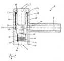
- FIG. 1 is, as an example of the prior art, a Rohranbohrarmatur 1 shown half cut.
- the examples of FIGS. 1 and 2 are not part of the invention.
- the Rohranbohrarmatur 1 is essentially a pipe fitting with three outputs and with internals.
- the Rohranbohrarmatur 1 comprises a housing 2, which has a Bohrstutzen 3, which can be mounted perpendicular to the tube axis of a media-conveying pipe.
- the media-conveying pipe is not shown here and can promote gas, water or other medium.
- the pipe tapping fitting 1 serves to divert a branching pipe, for example a connecting line for a house from a main line, for example, a supply line in the street underground. With the pipe tapping fitting 1, the connection operation can be performed without interruption of the conveyance of the medium conveyed in the main pipe and without loss of the medium. Especially for gas or chemical delivery lines, it is important for reasons of environmental protection to work as possible without loss of the medium
- the drill pipe 3 has at a lower end 4 a connection region 5, with which the drill pipe 3 can be connected to the pipe, not shown.
- the connection of the Bohrstutzens 3 with the pipe can be prepared for example with a pipe clamp in plastic pipes with an electroweldable saddle part or with another known connection method.
- an operating opening 7 is shown at the upper end 6 of the Bohrstutzens 3 .
- the operating opening 7 serves as access for a tool that must be introduced for the connection process of the pipe tapping fitting 1 to the main line in the drill neck 3.
- a branch pipe 8 is arranged at an angle to the drill pipe 3.
- the branch pipe 8 is arranged approximately at right angles to the drill pipe 3.
- angles greater or less than 90 ° are also conceivable. This ensures that the connecting line, which must be connected to the branch pipe 8, can be connected as possible without diversion to the main line.
- the connection line which was also not shown here, can be connected to the branch pipe 8 by the same connection method as described above.
- the pipe tapping fitting 1 is shown in a state as the fitting is delivered prepared for installation on the site.
- the cutting bush 9 is essentially a cylindrical component, which is arranged concentrically in the drill neck 3.
- the cutting bushing 9 comprises from below to the top four areas: a cutting portion 10, which is formed as a core drill or a cutting sleeve 11, a drive portion 12, in which a tool for actuating the cutting sleeve 9 can be accommodated, a threaded portion 13, with the cutting sleeve 9 axially and radially in the Bohrstutzen 3 is movable and a spatially separated from the threaded portion 13 sealing portion 19 which seals the cutting bushing 9 to the drill neck 3 of the housing 2.
- the drive region 12 has on the inside a tool holder 14.
- the tool holder 14 is designed such that a tool that is introduced through the operating opening 7 into the drill neck 3 is enclosed by the tool holder 14.
- the tool can be a standard Allen key or a special tool. With this tool, the cutting sleeve 9 is screwed in or out with respect to the drill pipe 3, as is the case with a core drill.
- the drive region 12 can also have a closure plate 15, with which it is prevented that the medium from the main line in the region of the operating opening 7 can flow.
- the operating opening 7 can be additionally closed with a screw cap or a cover that is in FIG. 6 is shown.
- the cutting sleeve 11 is made of a material suitable for severing the wall of the media-conveying tube.
- a cylindrical brass sleeve 11 with a ground cutting edge 16 is sufficient.
- Only the cutting area 10 is made of metal.
- the remaining regions of the cutting bushing 9 can be made of the same plastic material as the housing 2 or of a plastic material compatible therewith. If a heavier design is desired, the entire cutting bushing 9 can be made of the same material, such as brass.
- the cutting area 10 is formed as thin as possible and takes on the inside of the plastic part, which from the wall of the media-conveying pipe was cut out.
- the cutting sleeve 11 has on the inside a special thread 17 which serves to receive the cut-out plastic part in the cutting sleeve 11 when drilling the tube. With the special thread 17 is further prevented that when unscrewing the cut out of the tube plastic part within the cutting sleeve 9 tilts in an inclined position or even falls out of the cutting sleeve 9 in the pipe.
- the threaded portion 13 is like the cutting sleeve 11 is cylindrical, but not necessarily made of metal or brass. With the threaded portion 13, the cutting sleeve 9 is rotatably and operably disposed in the Bohrstutzen 3.
- the threaded portion 13 of the cutting bushing 9 has on the outside an external thread 18 and on the inside a sealing area 19.
- the drill neck 3 has an internal thread 20, which is complementary to the external thread 18 of the cutting bushing 9 is formed.
- the drill neck 9 has an annular receiving pocket 21, which accommodates both the entire sealing area 19 and the complementary threads 18, 20 for the most part.
- the annular configuration of the receiving pocket 21 ensures that both the sealing region 19 and the complementary threads 18, 20 can be arranged in the smallest possible space.
- the height of the Rohranbohrarmatur 1 is kept as small as possible.
- the sealing region 19 of the cutting bush 9 has an annular groove 22 for receiving a sealing means 23.
- the sealant is, for example, an O-ring seal 23, which is available in many standard sizes.
- the annular groove 22 is arranged in the cylindrical sealing region 19, which is formed spatially separated from the complementary threads 18, 20 on the cutting bushing 9. Due to the spatially separated arrangement of the sealing region 19 and the thread 18, 20 a simple production and a material-saving dimensioning of the cutting bush is possible.
- the wall parts, the sealing functions have been designed precisely for this task, and on the other hand, the wall parts having the threads 18, 20 can be designed precisely for that task. In production this means that in the example of FIG.
- the inner wall of the cutting bushing 9 and the closer to the central axis of the Bohrstutzens 3 wall of the receiving pocket 21 can be formed as smooth and uniform as possible.
- the best possible sealing effect between the drill pipe 3 and cutting bushing 9 is achieved, so that the Rohranbohrarmatur 1 can also be used for high media pressures.
- the formation of the annular receiving pocket 21 of the Bohrstutzens 3 with the internal thread 20 can be simplified by making the Bohrstutzens 3 in two parts. By manufacturing in individual parts, the inside of the receiving pocket can be easily processed or deformed and then the items can be joined together by gluing, welding or screwing to form an annular receiving pocket 21.
- the annular grooves 22 and the O-ring seals 23 may, instead of being formed on the sealing area 19 of the cutting bushing 9, may also be formed on the opposite wall areas of the drill neck 3 of the housing 2.
- the sealing means 23 is arranged on a diameter which is substantially smaller than the diameter of the complementary threads 18, 20. As a result, the sealing effect of the fitting 1 is further improved, since with a smaller diameter, the forces occurring at the sealing means 23 become smaller.
- the largest diameter, ie the outer diameter of the O-ring seal 23 is smaller than the smallest diameter, ie, the inner diameter of the complementary threads 18, 20. Because the complementary threads 18, 20 in comparison to the O-ring seal 23 a relatively have large diameter, the operation of the cutting sleeve 9 is much easier. The feed of the cutting bushing 9, at the same pitch angle, proportional to the diameter of the complementary thread 18, 20 per revolution greater.
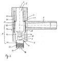
- FIG. 2 is the pipe tapping fitting 1 of FIG. 1 shown again cut here, however, in the position after the complete screwing of the cutting sleeve 9 in the wall of the media-conveying pipe.
- the pipe has already been drilled and a part of the pipe wall was received in the cutting sleeve 10. Too deep screwing can be prevented by a stop.
- the cutting sleeve 9 is still guided and sealed by the receiving pocket 21 of the drill neck 3.
- the next step, starting from this position, the cutting sleeve 9 is unscrewed again to the position of FIG. 1 ,
- the tool for actuating the cutting bushing 9 can be removed from the operating opening 7.
- the operating opening 7 with an in FIG. 6 End cap shown or closed with a screw cap.
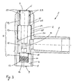
- FIGS. 3 to 5 an embodiment of the invention Rohranbohrarmatur 1 is shown.
- the cutting bush 9 has a different design than in the FIGS. 1 and 2 on.
- the sealing region 19 is also arranged spatially separated from the complementary threads 18, 20 here. The spatial separation is even more pronounced here than in the FIGS. 1 and 2 ,
- the cutting bushing 9 has here then on the outer thread 18, which is formed on a first wall portion 24 of the cutting bush 9, nor a second wall portion 25 which is connected via a shoulder 26 with the first wall portion 24.
- the sealing means 23 is formed on this second wall portion 25 of the cutting bush 9.
- the sealing means 23 is also arranged on a circle, with an outer diameter which is smaller than the inner diameter of the sealing region 19.
- the embodiment of FIGS. 3 to 5 is characterized by a good leadership of the cutting sleeve 9 when screwing in and out.
- the sealing effect can be further increased by a second O-ring seal 23
- the height of a can in a second annular groove 22 in the sealing region 19 of the cutting Minimum be limited.
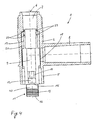
- FIG. 5 is the cutting bushing 9 off Figures 3 and 4 shown alone. Here are the individual areas of the cutting box 9 clearly visible. From bottom to top, the cutting sleeve 11, the drive portion 12 with the tool holder 14, the threaded portion 13 with the external thread and the sealing portion 19 with the annular grooves 22 and the O-ring seals 23rd
- FIG. 6 is another example of a Rohranbohrarmatur invention shown connected to a media-conveying pipe 30.
- the example of FIG. 6 is not part of the invention.
- the cutting bush 9 is shown in a state in which the cutting bushing 9 has completely severed the media-conveying pipe 30.
- the cutting bush 9 is shown in a state in which the cutting bushing 9 completely releases the passage from the media-conveying pipe in the branch pipe 8.
- the tapping fitting 1 of FIG. 6 can be connected in different ways with the media-conveying tube 30. In FIG. 6 this is indicated by a bond 31, by an electric welding connection 32 and by a pipe clamp half 33.
- the cutting bushing 9 is in the manufacture of the bottom of the pipe tapping fitting 1 to the state of the right half of FIG. 6 screwed. Subsequently, a substantially annular insert 34 is also introduced from below into the drill neck 3.
- the insert 34 may be glued, welded or screwed at the lower end of the Bohrstutzens 3.
- the insert 34 prevents the cutting bushing 9 from being screwed too deeply into the tube 30 when the tube 30 is being drilled. If the cutting bushing 9 were screwed too deep into the tube 30, at the upper end of the cutting bushing 9 no Sealing effect more guaranteed and the medium would escape during the tapping process from the tube 30. However, too deep screwing can also be prevented by a special design of the thread 18 in the lower area.
- the thread 18 can be cut to run or the length of the thread 18 can be chosen so short that the high torque that is necessary for the cutting process is transmitted only to a defined position. This ensures that the cutting bush 9 below this defined position no longer transmits torque and slips into space, so to speak.
- a screw cap 35 or a cover cap is also shown. With the screw cap 35, the tapping fitting 1 is additionally closed after completion of the tapping process.
- the tapping fitting 1 is used wherever a loss of the medium is undesirable or can pose a threat to the environment.
Landscapes
- Engineering & Computer Science (AREA)
- General Engineering & Computer Science (AREA)
- Mechanical Engineering (AREA)
- Branch Pipes, Bends, And The Like (AREA)
- Drilling And Boring (AREA)
- Earth Drilling (AREA)
- Drilling Tools (AREA)
- Perforating, Stamping-Out Or Severing By Means Other Than Cutting (AREA)
Abstract
Description
Die Erfindung bezieht sich auf eine Rohranbohrarmatur für ein medienförderndes Rohr, umfassend ein Gehäuse, das einen unter einem Winkel zur Rohrachse anbringbaren Bohrstutzen zum Anbohren der Rohrwand und einen unter einem Winkel zum Bohrstutzen angeordneten Abzweigstutzen aufweist, wobei im Bohrstutzen eine drehbetätigbare Schneidbüchse mit einem Schneidbereich, einem Gewindebereich komplementär zum Gewinde des Bohrstutzens und einem Dichtungsbereich zwischen Bohrstutzen und Schneidbüchse mit mindestens einem Dichtungsmittel zur Abdichtung des medienfördernden Rohres gegen Aussen angeordnet ist, wobei das Dichtungsmittel radial nach innen beabstandet von den komplementären Gewinden angeordnet ist, vgl. Oberbegriff des Anspruchs 1 bekannt aus der
Aus der
Aus der
Ausgehend vom Stand der Technik nach
Diese Aufgabe wird gelöst durch eine Rohranbohrarmatur mit den Merkmalen des Patentanspruchs 1.This object is achieved by a pipe tapping fitting with the features of
Bevorzugte Weiterbildungen der Erfindung ergeben sich aus den abhängigen Patentansprüchen.Preferred embodiments of the invention will become apparent from the dependent claims.
Es ist von Vorteil, dass die Rohranbohrarmatur einen möglichst hohen Druck des Fördermittels aushalten kann. Dies wird dadurch erreicht, dass das Dichtungsmittel zwischen Bohrstutzen und Schneidbüchse radial nach innen und beabstandet von den komplementären Gewinden angeordnet ist. Die Kraft, die auf das elastische Dichtungsmittel wirkt, nimmt zu mit dem Durchmesser des Dichtungsmittels.It is advantageous that the Rohranbohrarmatur can withstand the highest possible pressure of the conveyor. This is achieved in that the sealing means between the drill pipe and cutting bushing is arranged radially inwardly and spaced from the complementary threads. The force acting on the elastic sealant increases with the diameter of the sealant.
Es ist auch von Vorteil, dass die Rohranbohrarmatur möglichst einfach hergestellt werden kann. Dies wird dadurch erreicht, dass das Dichtungsmittel zwischen dem Bohrstutzen des Gehäuses und der Schneidbüchse in einem einförmigen und vom Gewinde beabstandeten Dichtungsbereich der Schneidbüchse angeordnet ist. Durch die Zuordnung der Funktionen Schneiden, Dichten, Befestigen und Antreiben zu räumlich getrennten Bereichen wird erreicht, dass die Dimensionierung der Schneidbüchse optimal auf der jeweiligen Funktion der unterschiedlichen Bereiche ausgerichtet werden kann.It is also advantageous that the Rohranbohrarmatur can be made as simple as possible. This is achieved in that the sealing means is arranged between the drill neck of the housing and the cutting bushing in a single and spaced from the thread sealing portion of the cutting bushing. The assignment of the functions cutting, sealing, fastening and driving to spatially separated areas ensures that the dimensioning of the cutting bush can be optimally aligned to the respective function of the different areas.
Ausführungsbeispiele der Erfindung werden anhand der Figuren beschrieben. Es zeigen:
-
Figur 1 -
Figur 2Figur 1 -
Figur 3 -
Figur 4Figur 3 -
Figur 5Fig 3 und4 und -
Figur 6 einen Schnitt durch eine weitere erfindungsgemäße Rohranbohrarmatur, die mit einem medienfördernden Rohr verbunden ist.
-
FIG. 1 a section through a Rohranbohrarmatur before drilling a media-conveying pipe, which is not part of the invention, -
FIG. 2 a section through the RohranbohrarmaturFIG. 1 , in the state after the drilling of the media-conveying pipe, -
FIG. 3 a section through an inventive pipe tapping fitting before drilling a media-conveying pipe, -
FIG. 4 a section through the RohranbohrarmaturFIG. 3 , in the state after the drilling of the media-conveying pipe, -
FIG. 5 a section through the cutting sleeve of RohranbohrarmaturFig. 3 and4 and -
FIG. 6 a section through a further Rohranbohrarmatur invention, which is connected to a media-conveying pipe.
In
Der Bohrstutzen 3 weist an einem unteren Ende 4 einen Verbindungsbereich 5 auf, mit dem der Bohrstutzen 3 mit dem nicht dargestellten Rohr verbunden werden kann. Die Verbindung des Bohrstutzens 3 mit dem Rohr kann beispielsweise mit einer Rohrschelle, bei Kunststoffrohren mit einem elektroschweissbaren Sattelteil oder mit einem anderen bekannten Verbindungsverfahren hergestellt werden. Am oberen Ende 6 des Bohrstutzens 3 ist eine Bedienungsöffnung 7 dargestellt. Die Bedienungsöffnung 7 dient als Zugang für ein Werkzeug, das für den Anschlussvorgang der Rohranbohrarmatur 1 an die Hauptleitung in den Bohrstutzen 3 eingeführt werden muss.The
Unter einem Winkel zum Bohrstutzen 3 ist ein Abzweigstutzen 8 angeordnet. In
Als Einbau im Bohrstutzen 3 ist eine Schneidbüchse 9 dargestellt. Die Schneidbüchse 9 ist im Wesentlichen ein zylindrisches Bauteil, das konzentrisch in dem Bohrstutzen 3 angeordnet ist. Die Schneidbüchse 9 umfasst von unten nach oben vier Bereiche: einen Schneidbereich 10, der als einen Kernbohrer oder eine Schneidhülse 11 ausgebildet ist, einen Antriebsbereich 12, in der ein Werkzeug zur Betätigung der Schneidbüchse 9 aufgenommen werden kann, einen Gewindebereich 13, mit der die Schneidbüchse 9 axial und radial in dem Bohrstutzen 3 bewegbar ist und einen räumlich vom Gewindebereich 13 getrennten Dichtungsbereich 19, der die Schneidbüchse 9 zum Bohrstutzen 3 des Gehäuses 2 abdichtet.As installation in the drill neck 3 a cutting bushing 9 is shown. The
Der Antriebsbereich 12 weist auf der Innenseite eine Werkzeugaufnahme 14 auf. Die Werkzeugaufnahme 14 ist so ausgebildet, dass ein Werkzeug, dass durch die Bedienungsöffnung 7 in den Bohrstutzen 3 eingeführt wird von der Werkzeugaufnahme 14 umschlossen wird. Das Werkzeug kann ein normaler Innensechskantschlüssel oder ein Spezialwerkzeug sein. Mit diesem Werkzeug wird die Schneidbüchse 9 gegenüber dem Bohrstutzen 3 ein- oder ausgeschraubt, wie das bei einem Kernbohrer der Fall ist. Der Antriebsbereich 12 kann auch eine Abschlussplatte 15 aufweisen, mit der verhindert wird, dass das Medium aus der Hauptleitung im Bereich der Bedienungsöffnung 7 fliessen kann. Die Bedienungsöffnung 7 kann zusätzlich verschlossen werden mit einer Schraubkappe oder einen Abschlussdeckel, der in
Die Schneidhülse 11 ist aus einem Material hergestellt, das geeignet ist, die Wand des medienfördernden Rohres zu durchtrennen. Für Kunststoffrohre aus Polyäthylen oder Polypropylen genügt eine zylindrische Messinghülse 11 mit einer geschliffenen Schneidkante 16. Nur der Schneidbereich 10 ist aus Metall hergestellt. Die übrigen Bereiche der Schneidbüchse 9 können aus dem gleichen Kunststoffmaterial wie das Gehäuse 2 oder aus einem damit kompatiblen Kunststoffmaterial hergestellt werden. Wenn eine schwerere Ausführung gewünscht wird, kann auch die gesamte Schneidbüchse 9 aus demselben Material, beispielsweise Messing, hergestellt werden. Der Schneidbereich 10 ist so dünnwandig wie möglich ausgebildet und nimmt auf der Innenseite das Kunststoffteil auf, das aus der Wand des medienfördernden Rohres ausgeschnitten wurde. Die Schneidhülse 11 weist auf der Innenseite ein Spezialgewinde 17 auf, das dazu dient, beim Anbohren des Rohres das ausgeschnittene Kunststoffteil in die Schneidhülse 11 aufzunehmen. Mit dem Spezialgewinde 17 wird weiterhin verhindert, dass, beim Ausschrauben das aus dem Rohr ausgeschnittene Kunststoffteil innerhalb der Schneidbüchse 9 in einer Schräglage kippt oder sogar aus der Schneidbüchse 9 in das Rohr zurückfällt.The cutting
Der Gewindebereich 13 ist wie die Schneidhülse 11 zylindrisch ausgebildet, jedoch nicht zwingend aus Metall oder Messing. Mit dem Gewindebereich 13 wird die Schneidbüchse 9 drehbar und betätigbar in dem Bohrstutzen 3 angeordnet. Der Gewindebereich 13 der Schneidbüchse 9 weist auf der Aussenseite ein Aussengewinde 18 und auf der Innenseite einen Dichtungsbereich 19 auf. Der Bohrstutzen 3 weist ein Innengewinde 20 auf, der komplementär zum Aussengewinde 18 der Schneidbüchse 9 ausgebildet ist.The threaded
In dem Beispiel von
Der Dichtungsbereich 19 der Schneidbüchse 9 weist eine Ringnut 22 zur Aufnahme eines Dichtungsmittels 23 auf. Das Dichtungsmittel ist beispielsweise eine O-Ringdichtung 23, die in vielen Standardgrössen erhältlich ist. Die Ringnut 22 ist in dem zylindrischen Dichtungsbereich 19 angeordnet, der räumlich getrennt von den komplementären Gewinden 18, 20 an der Schneidbüchse 9 ausgebildet ist. Durch die räumlich getrennte Anordnung des Dichtungsbereiches 19 und der Gewinde 18, 20 wird eine einfache Herstellung und eine materialsparende Dimensionierung der Schneidbüchse möglich. Einerseits können die Wandteile, die Dichtungsfunktionen haben genau für diese Aufgabe ausgelegt werden und andererseits können die Wandteile, die die Gewinde 18, 20 aufweisen, genau für jene Aufgabe ausgelegt werden. In der Herstellung bedeutet dies, dass im Beispiel von
Das Dichtungsmittel 23 ist auf einem Durchmesser angeordnet, der wesentlich kleiner ist als der Durchmesser der komplementären Gewinde 18, 20. Hierdurch wird die Dichtwirkung der Armatur 1 nochmals verbessert, da mit kleinerem Durchmesser die an dem Dichtungsmittel 23 auftretenden Kräfte geringer werden. In den
In
In den
Die Dichtwirkung kann weiter erhöht werden durch eine zweite O-Ringdichtung 23 in einer zweiten Ringnut 22 im Dichtungsbereich 19 der Schneidbüchse 9. Bei der richtigen Dimensionierung der Längenverhältnisse des Dichtungsbereiches 19 und der komplementären Gewinde 18, 20 und durch die Anordnung der Ringnuten 22 mit den O-Ringdichtungen 23 in der richtigen Höhe kann die Bauhöhe auf ein Minimum beschränkt werden.The sealing effect can be further increased by a second O-
In
In
Am oberen Ende des Bohrstutzens 3 im Bereich der Bedienungsöffnung 7 ist ebenfalls eine Schraubkappe 35 oder einen Abschlussdeckel dargestellt. Mit der Schraubkappe 35 wird die Anbohrarmatur 1 nach erfolgtem Anbohrvorgang zusätzlich verschlossen. Die Anbohrarmatur 1 wird überall dort eingesetzt, wo ein Verlust des Mediums unerwünscht ist oder eine Gefahr für die Umwelt bedeuten kann.At the upper end of the
Claims (4)
- Pipe-drilling fitting (1) for a medium-conveying pipe, comprising a housing (2) which has a drilling stub (3), which can be fitted at an angle to the pipe axis, for drilling into the pipe wall, and a branch stub (8) which is arranged at an angle to the drilling stub (3), wherein
a rotationally actuable cutting bush (9) having a cutting region (10, 11), a threaded region (13, 24) complementary to the thread (20) of the drilling stub (3) and a sealing region (19, 25) between drilling stub (3) and cutting bush (9) and having at least one sealing means (23) for sealing the medium-conveying pipe with respect to the outside is arranged in the drilling stub (3), a shoulder (26) is formed between the threaded region (13, 24) and the sealing region (19, 25), in such a manner that the sealing region (19, 25) has a significantly smaller diameter than the threaded region (13, 24),
characterized
in that the sealing region (19, 25), as seen in the axial direction, is arranged further away from the cutting region (10, 11) than the threaded region (13, 24) is. - Pipe-drilling fitting according to Claim 1, characterized in that the sealing means (23) between the drilling stub (3) of the housing (2) and the cutting bush (9) is arranged in a uniform sealing region (19), which is at a distance from the screw thread (18), of the cutting bush.
- Pipe-drilling fitting according to Claim 1 or 2, characterized in that the sealing region (19) has an annular groove (22) for accommodating the sealing means (23) .
- Pipe-drilling fitting according to one of Claims 1 to 3, characterized in that the drilling stub (3) is formed integrally with the housing (2) from a plastics material.
Applications Claiming Priority (2)
| Application Number | Priority Date | Filing Date | Title |
|---|---|---|---|
| DE19932401 | 1999-07-14 | ||
| DE19932401.8A DE19932401B4 (en) | 1999-07-14 | 1999-07-14 | Rohranbohrarmatur |
Publications (2)
| Publication Number | Publication Date |
|---|---|
| EP1069367A1 EP1069367A1 (en) | 2001-01-17 |
| EP1069367B1 true EP1069367B1 (en) | 2011-08-17 |
Family
ID=7914413
Family Applications (1)
| Application Number | Title | Priority Date | Filing Date |
|---|---|---|---|
| EP20000108580 Revoked EP1069367B1 (en) | 1999-07-14 | 2000-04-20 | Tapping fitting for pipes |
Country Status (6)
| Country | Link |
|---|---|
| US (1) | US6260573B1 (en) |
| EP (1) | EP1069367B1 (en) |
| JP (1) | JP4545288B2 (en) |
| AT (1) | ATE520921T1 (en) |
| BR (1) | BR0002724A (en) |
| DE (1) | DE19932401B4 (en) |
Cited By (1)
| Publication number | Priority date | Publication date | Assignee | Title |
|---|---|---|---|---|
| DE102015122731B3 (en) * | 2015-12-23 | 2016-12-22 | Friatec Aktiengesellschaft | Tapping fitting and a corresponding manufacturing process |
Families Citing this family (9)
| Publication number | Priority date | Publication date | Assignee | Title |
|---|---|---|---|---|
| US6612330B1 (en) * | 2000-07-06 | 2003-09-02 | Keyspan Corporation | No interrupt service tee and method |
| GB2369662A (en) * | 2000-11-29 | 2002-06-05 | Uponor Ltd | Tapping fitting for use with a plastics pipe |
| ES2223970T3 (en) * | 2002-01-12 | 2005-03-01 | Agru Kunststofftechnik Gmbh | DEVICE FOR DERIVING PIPES. |
| EP1517076A1 (en) * | 2002-06-12 | 2005-03-23 | Marcelo D. Hombravella Abbad | Device for producing bypasses under pressure in fluid piping systems |
| DE10310171B4 (en) * | 2003-01-24 | 2006-09-07 | Friatec Ag | Tapping Bridge |
| GB2421553A (en) * | 2004-12-23 | 2006-06-28 | Uponor Innovation Ab | Tapping tee assembly with an integrated cutter and dual electrofusion elements |
| CA2789619A1 (en) | 2010-02-12 | 2011-08-18 | Elster Perfection Corporation | Cutter assembly |
| DK3366969T3 (en) | 2017-02-28 | 2022-08-15 | Georg Fischer Wavin Ag | PIPE DRILLING FITTING |
| KR102229571B1 (en) * | 2020-09-03 | 2021-03-18 | (주) 폴리텍 | Branch joint pipe |
Family Cites Families (24)
| Publication number | Priority date | Publication date | Assignee | Title |
|---|---|---|---|---|
| US2839075A (en) * | 1954-02-16 | 1958-06-17 | Mueller Co | Service t for plastic mains |
| US3349792A (en) * | 1965-02-24 | 1967-10-31 | Phillips Petroleum Co | Tapping t and valve |
| US3756261A (en) * | 1971-11-16 | 1973-09-04 | Amp Inc | Method and apparatus for connecting a tap to a pipeline |
| US4029118A (en) * | 1975-07-03 | 1977-06-14 | Phillips Petroleum Company | Tapping apparatus and method |
| US4076038A (en) * | 1976-01-05 | 1978-02-28 | Phillips Petroleum Company | Tapping tee cutter having relieved sidewall |
| JPS583991Y2 (en) * | 1977-03-25 | 1983-01-24 | 積水化学工業株式会社 | branch pipe fittings |
| US4258742A (en) * | 1979-04-03 | 1981-03-31 | Phillips Petroleum Company | Tapping apparatus |
| JPS6128994U (en) * | 1984-07-24 | 1986-02-21 | 三菱樹脂株式会社 | branch pipe fittings |
| DE3561484D1 (en) * | 1984-08-08 | 1988-02-25 | Fischer Ag Georg | Shaped piercing piece consisting of weldable plastics |
| DE3723898A1 (en) * | 1987-07-18 | 1989-01-26 | Friedrichsfeld Gmbh | Boring fitting |
| DE3830395C1 (en) | 1988-09-07 | 1990-01-11 | Friedrichsfeld Gmbh Keramik- Und Kunststoffwerke, 6800 Mannheim, De | Boring fitting |
| US5076318A (en) * | 1990-08-23 | 1991-12-31 | Phillips Petroleum Company | Tapping tee cutter for plastic pipe |
| DE9115052U1 (en) * | 1991-12-04 | 1993-04-01 | Gebr. Rehbein, 42855 Remscheid | Milling cutter tapping fitting |
| US5348045A (en) | 1992-02-15 | 1994-09-20 | Manibs Spezialarmaturen Gmbh & Co. Kg | Pipe clamp for plastic supply pipelines, particularly a tapping clamp |
| DE4217982C2 (en) * | 1992-05-30 | 1994-06-30 | Friatec Keramik Kunststoff | Valve tapping valve |
| JP2562886Y2 (en) * | 1993-12-14 | 1998-02-16 | 東亜高級継手バルブ製造株式会社 | Plastic branch pipe fittings |
| DE4408817C1 (en) * | 1994-03-16 | 1995-06-22 | Ewe Wilhelm Gmbh & Co Kg | Valve/drilling fitting with integrated cut-off of operation |
| DE9419070U1 (en) * | 1994-11-28 | 1995-03-16 | GAWATEC Rohrverbindungssysteme GmbH & Co. KG, 49406 Barnstorf | Branch that can be attached to a supply line, in particular for a house connection line |
| US5577529A (en) * | 1995-01-19 | 1996-11-26 | Plasson Maagan Michael Industries Ltd. | Tapping fittings |
| IL114505A (en) | 1995-07-09 | 1998-02-22 | Plasson Maagan Michael Ind Ltd | Tapping fitting |
| DE19623004A1 (en) * | 1996-06-08 | 1997-12-18 | Manibs Spezialarmaturen | Valve tapping fitting for plastic supply lines, preferably under media pressure |
| US5896885A (en) | 1996-06-11 | 1999-04-27 | Phillips Petroleum Company | Tapping saddle pipe fitting |
| DE19630029A1 (en) * | 1996-07-25 | 1998-01-29 | Manibs Spezialarmaturen | Valve tapping fitting for plastics pipelines under pressure |
| IL122286A (en) * | 1996-11-30 | 2002-02-10 | Friatec Ag | Pipe tapping device |
-
1999
- 1999-07-14 DE DE19932401.8A patent/DE19932401B4/en not_active Expired - Lifetime
-
2000
- 2000-04-20 AT AT00108580T patent/ATE520921T1/en active
- 2000-04-20 EP EP20000108580 patent/EP1069367B1/en not_active Revoked
- 2000-06-19 JP JP2000183047A patent/JP4545288B2/en not_active Expired - Fee Related
- 2000-07-07 US US09/612,474 patent/US6260573B1/en not_active Expired - Fee Related
- 2000-07-12 BR BR0002724A patent/BR0002724A/en not_active IP Right Cessation
Cited By (2)
| Publication number | Priority date | Publication date | Assignee | Title |
|---|---|---|---|---|
| DE102015122731B3 (en) * | 2015-12-23 | 2016-12-22 | Friatec Aktiengesellschaft | Tapping fitting and a corresponding manufacturing process |
| EP3184872A1 (en) | 2015-12-23 | 2017-06-28 | Friatec Aktiengesellschaft | Drill fitting and corresponding production method |
Also Published As
| Publication number | Publication date |
|---|---|
| JP4545288B2 (en) | 2010-09-15 |
| DE19932401A1 (en) | 2001-01-18 |
| EP1069367A1 (en) | 2001-01-17 |
| ATE520921T1 (en) | 2011-09-15 |
| US6260573B1 (en) | 2001-07-17 |
| DE19932401B4 (en) | 2017-08-31 |
| JP2001041384A (en) | 2001-02-13 |
| BR0002724A (en) | 2001-03-13 |
Similar Documents
| Publication | Publication Date | Title |
|---|---|---|
| DE102007000882B4 (en) | Improved tapping branch arrangement with a cap arrangement | |
| EP1290371B1 (en) | Tapping stop valve | |
| EP1069367B1 (en) | Tapping fitting for pipes | |
| DE3808674C2 (en) | Tapping valve | |
| DE19531913A1 (en) | Drilling fitting for plastics supply conduits under medium pressure | |
| EP0736718B1 (en) | Tapping apparatus for plastic conduits, especially under pressure | |
| DE4309941A1 (en) | Tapping fitting | |
| EP0811799B1 (en) | Tapping device with valve for supply plastic pipes under pressure | |
| DE19629459C2 (en) | Tapping fitting for plastic pipes | |
| EP0734499B1 (en) | Method of broaching a line and pipe broaching unit for carrying out the method | |
| DE10233863B4 (en) | Connection block for sanitary fittings | |
| EP1035367B1 (en) | Boring device for a branching valve | |
| DE4408817C1 (en) | Valve/drilling fitting with integrated cut-off of operation | |
| EP1590593B1 (en) | Tapping valve having a safety function | |
| DE10320997B4 (en) | Valve tapping machine | |
| DE102005008398B4 (en) | Tapping fitting for plastic pipes and method for connecting a tapping fitting | |
| EP1441168B1 (en) | Tapping device with valve | |
| DE19750352C1 (en) | Branch drill assembly for fluid pipe | |
| DE19603254C2 (en) | Valve tapping fitting for pipelines under media pressure | |
| DE3704321A1 (en) | Milling-cutter spot-drilling fitting | |
| EP0845630A2 (en) | Tapping apparatus | |
| DE19749531C1 (en) | Device for transferring fluids from a stationary to a rotating machine part | |
| DE102011001220B4 (en) | connection device | |
| DE19630028C2 (en) | Valve tapping fitting for plastic supply lines, preferably under media pressure | |
| DE4010177A1 (en) | Device for venting pipe line - has valve which can be opened by rotating screwed operating rod |
Legal Events
| Date | Code | Title | Description |
|---|---|---|---|
| PUAI | Public reference made under article 153(3) epc to a published international application that has entered the european phase |
Free format text: ORIGINAL CODE: 0009012 |
|
| AK | Designated contracting states |
Kind code of ref document: A1 Designated state(s): AT BE CH CY DE DK ES FI FR GB GR IE IT LI LU MC NL PT SE |
|
| AX | Request for extension of the european patent |
Free format text: AL;LT;LV;MK;RO;SI |
|
| 17P | Request for examination filed |
Effective date: 20010710 |
|
| AKX | Designation fees paid |
Free format text: AT BE CH CY DE DK ES FI FR GB GR IE IT LI LU MC NL PT SE |
|
| GRAP | Despatch of communication of intention to grant a patent |
Free format text: ORIGINAL CODE: EPIDOSNIGR1 |
|
| RAP1 | Party data changed (applicant data changed or rights of an application transferred) |
Owner name: GEORG FISCHER WAVIN AG |
|
| GRAS | Grant fee paid |
Free format text: ORIGINAL CODE: EPIDOSNIGR3 |
|
| GRAA | (expected) grant |
Free format text: ORIGINAL CODE: 0009210 |
|
| AK | Designated contracting states |
Kind code of ref document: B1 Designated state(s): AT BE CH CY DE DK ES FI FR GB GR IE IT LI LU MC NL PT SE |
|
| REG | Reference to a national code |
Ref country code: GB Ref legal event code: FG4D Free format text: NOT ENGLISH |
|
| REG | Reference to a national code |
Ref country code: CH Ref legal event code: EP |
|
| REG | Reference to a national code |
Ref country code: IE Ref legal event code: FG4D Free format text: LANGUAGE OF EP DOCUMENT: GERMAN |
|
| REG | Reference to a national code |
Ref country code: DE Ref legal event code: R096 Ref document number: 50016152 Country of ref document: DE Effective date: 20111013 |
|
| REG | Reference to a national code |
Ref country code: NL Ref legal event code: VDEP Effective date: 20110817 |
|
| PG25 | Lapsed in a contracting state [announced via postgrant information from national office to epo] |
Ref country code: FI Free format text: LAPSE BECAUSE OF FAILURE TO SUBMIT A TRANSLATION OF THE DESCRIPTION OR TO PAY THE FEE WITHIN THE PRESCRIBED TIME-LIMIT Effective date: 20110817 Ref country code: NL Free format text: LAPSE BECAUSE OF FAILURE TO SUBMIT A TRANSLATION OF THE DESCRIPTION OR TO PAY THE FEE WITHIN THE PRESCRIBED TIME-LIMIT Effective date: 20110817 Ref country code: PT Free format text: LAPSE BECAUSE OF FAILURE TO SUBMIT A TRANSLATION OF THE DESCRIPTION OR TO PAY THE FEE WITHIN THE PRESCRIBED TIME-LIMIT Effective date: 20111219 Ref country code: SE Free format text: LAPSE BECAUSE OF FAILURE TO SUBMIT A TRANSLATION OF THE DESCRIPTION OR TO PAY THE FEE WITHIN THE PRESCRIBED TIME-LIMIT Effective date: 20110817 |
|
| PG25 | Lapsed in a contracting state [announced via postgrant information from national office to epo] |
Ref country code: CY Free format text: LAPSE BECAUSE OF FAILURE TO SUBMIT A TRANSLATION OF THE DESCRIPTION OR TO PAY THE FEE WITHIN THE PRESCRIBED TIME-LIMIT Effective date: 20110817 Ref country code: GR Free format text: LAPSE BECAUSE OF FAILURE TO SUBMIT A TRANSLATION OF THE DESCRIPTION OR TO PAY THE FEE WITHIN THE PRESCRIBED TIME-LIMIT Effective date: 20111118 |
|
| REG | Reference to a national code |
Ref country code: IE Ref legal event code: FD4D |
|
| PG25 | Lapsed in a contracting state [announced via postgrant information from national office to epo] |
Ref country code: IE Free format text: LAPSE BECAUSE OF FAILURE TO SUBMIT A TRANSLATION OF THE DESCRIPTION OR TO PAY THE FEE WITHIN THE PRESCRIBED TIME-LIMIT Effective date: 20110817 |
|
| PG25 | Lapsed in a contracting state [announced via postgrant information from national office to epo] |
Ref country code: IT Free format text: LAPSE BECAUSE OF FAILURE TO SUBMIT A TRANSLATION OF THE DESCRIPTION OR TO PAY THE FEE WITHIN THE PRESCRIBED TIME-LIMIT Effective date: 20110817 |
|
| PLBI | Opposition filed |
Free format text: ORIGINAL CODE: 0009260 |
|
| PLAX | Notice of opposition and request to file observation + time limit sent |
Free format text: ORIGINAL CODE: EPIDOSNOBS2 |
|
| PG25 | Lapsed in a contracting state [announced via postgrant information from national office to epo] |
Ref country code: DK Free format text: LAPSE BECAUSE OF FAILURE TO SUBMIT A TRANSLATION OF THE DESCRIPTION OR TO PAY THE FEE WITHIN THE PRESCRIBED TIME-LIMIT Effective date: 20110817 |
|
| 26 | Opposition filed |
Opponent name: FRIATEC AKTIENGESELLSCHAFT Effective date: 20120516 |
|
| REG | Reference to a national code |
Ref country code: DE Ref legal event code: R026 Ref document number: 50016152 Country of ref document: DE Effective date: 20120516 |
|
| PLBB | Reply of patent proprietor to notice(s) of opposition received |
Free format text: ORIGINAL CODE: EPIDOSNOBS3 |
|
| BERE | Be: lapsed |
Owner name: GEORG FISCHER WAVIN A.G. Effective date: 20120430 |
|
| PG25 | Lapsed in a contracting state [announced via postgrant information from national office to epo] |
Ref country code: MC Free format text: LAPSE BECAUSE OF NON-PAYMENT OF DUE FEES Effective date: 20120430 |
|
| REG | Reference to a national code |
Ref country code: CH Ref legal event code: PL |
|
| GBPC | Gb: european patent ceased through non-payment of renewal fee |
Effective date: 20120420 |
|
| REG | Reference to a national code |
Ref country code: FR Ref legal event code: ST Effective date: 20121228 |
|
| PG25 | Lapsed in a contracting state [announced via postgrant information from national office to epo] |
Ref country code: BE Free format text: LAPSE BECAUSE OF NON-PAYMENT OF DUE FEES Effective date: 20120430 Ref country code: GB Free format text: LAPSE BECAUSE OF NON-PAYMENT OF DUE FEES Effective date: 20120420 Ref country code: LI Free format text: LAPSE BECAUSE OF NON-PAYMENT OF DUE FEES Effective date: 20120430 Ref country code: CH Free format text: LAPSE BECAUSE OF NON-PAYMENT OF DUE FEES Effective date: 20120430 |
|
| PG25 | Lapsed in a contracting state [announced via postgrant information from national office to epo] |
Ref country code: FR Free format text: LAPSE BECAUSE OF NON-PAYMENT OF DUE FEES Effective date: 20120430 |
|
| PG25 | Lapsed in a contracting state [announced via postgrant information from national office to epo] |
Ref country code: ES Free format text: LAPSE BECAUSE OF FAILURE TO SUBMIT A TRANSLATION OF THE DESCRIPTION OR TO PAY THE FEE WITHIN THE PRESCRIBED TIME-LIMIT Effective date: 20111128 |
|
| REG | Reference to a national code |
Ref country code: AT Ref legal event code: MM01 Ref document number: 520921 Country of ref document: AT Kind code of ref document: T Effective date: 20120420 |
|
| PG25 | Lapsed in a contracting state [announced via postgrant information from national office to epo] |
Ref country code: AT Free format text: LAPSE BECAUSE OF NON-PAYMENT OF DUE FEES Effective date: 20120420 |
|
| APAH | Appeal reference modified |
Free format text: ORIGINAL CODE: EPIDOSCREFNO |
|
| APBM | Appeal reference recorded |
Free format text: ORIGINAL CODE: EPIDOSNREFNO |
|
| APBP | Date of receipt of notice of appeal recorded |
Free format text: ORIGINAL CODE: EPIDOSNNOA2O |
|
| APBQ | Date of receipt of statement of grounds of appeal recorded |
Free format text: ORIGINAL CODE: EPIDOSNNOA3O |
|
| PG25 | Lapsed in a contracting state [announced via postgrant information from national office to epo] |
Ref country code: LU Free format text: LAPSE BECAUSE OF NON-PAYMENT OF DUE FEES Effective date: 20120420 |
|
| REG | Reference to a national code |
Ref country code: DE Ref legal event code: R064 Ref document number: 50016152 Country of ref document: DE Ref country code: DE Ref legal event code: R103 Ref document number: 50016152 Country of ref document: DE |
|
| APBU | Appeal procedure closed |
Free format text: ORIGINAL CODE: EPIDOSNNOA9O |
|
| PGFP | Annual fee paid to national office [announced via postgrant information from national office to epo] |
Ref country code: DE Payment date: 20150421 Year of fee payment: 16 |
|
| RDAF | Communication despatched that patent is revoked |
Free format text: ORIGINAL CODE: EPIDOSNREV1 |
|
| RDAG | Patent revoked |
Free format text: ORIGINAL CODE: 0009271 |
|
| STAA | Information on the status of an ep patent application or granted ep patent |
Free format text: STATUS: PATENT REVOKED |
|
| 27W | Patent revoked |
Effective date: 20150610 |
|
| REG | Reference to a national code |
Ref country code: AT Ref legal event code: MA03 Ref document number: 520921 Country of ref document: AT Kind code of ref document: T Effective date: 20150610 |