EP1069191A1 - Abstichvorrichtung sowie Abstichverfahren - Google Patents
Abstichvorrichtung sowie Abstichverfahren Download PDFInfo
- Publication number
- EP1069191A1 EP1069191A1 EP00113436A EP00113436A EP1069191A1 EP 1069191 A1 EP1069191 A1 EP 1069191A1 EP 00113436 A EP00113436 A EP 00113436A EP 00113436 A EP00113436 A EP 00113436A EP 1069191 A1 EP1069191 A1 EP 1069191A1
- Authority
- EP
- European Patent Office
- Prior art keywords
- lance
- tap
- stuffing
- opening
- hole
- Prior art date
- Legal status (The legal status is an assumption and is not a legal conclusion. Google has not performed a legal analysis and makes no representation as to the accuracy of the status listed.)
- Granted
Links
- 238000010079 rubber tapping Methods 0.000 title claims abstract description 52
- 238000000034 method Methods 0.000 title claims abstract description 12
- 238000001816 cooling Methods 0.000 claims abstract description 25
- 239000000498 cooling water Substances 0.000 claims abstract description 12
- RYGMFSIKBFXOCR-UHFFFAOYSA-N Copper Chemical compound [Cu] RYGMFSIKBFXOCR-UHFFFAOYSA-N 0.000 claims abstract description 9
- 229910052802 copper Inorganic materials 0.000 claims abstract description 9
- 239000010949 copper Substances 0.000 claims abstract description 9
- 239000000463 material Substances 0.000 claims abstract description 9
- 229910000881 Cu alloy Inorganic materials 0.000 claims abstract description 7
- 238000002844 melting Methods 0.000 claims description 35
- 230000008018 melting Effects 0.000 claims description 35
- 150000001875 compounds Chemical class 0.000 claims description 3
- 238000003780 insertion Methods 0.000 claims description 3
- 230000037431 insertion Effects 0.000 claims description 3
- 239000000155 melt Substances 0.000 description 20
- 230000008878 coupling Effects 0.000 description 12
- 238000010168 coupling process Methods 0.000 description 12
- 238000005859 coupling reaction Methods 0.000 description 12
- 230000033001 locomotion Effects 0.000 description 10
- 238000011161 development Methods 0.000 description 4
- 230000018109 developmental process Effects 0.000 description 4
- 239000000969 carrier Substances 0.000 description 3
- 230000000694 effects Effects 0.000 description 3
- 238000004056 waste incineration Methods 0.000 description 3
- 239000007789 gas Substances 0.000 description 2
- 230000001174 ascending effect Effects 0.000 description 1
- 238000004140 cleaning Methods 0.000 description 1
- 238000002485 combustion reaction Methods 0.000 description 1
- 239000004020 conductor Substances 0.000 description 1
- 238000010276 construction Methods 0.000 description 1
- 230000007423 decrease Effects 0.000 description 1
- 230000002996 emotional effect Effects 0.000 description 1
- 230000007613 environmental effect Effects 0.000 description 1
- 230000017525 heat dissipation Effects 0.000 description 1
- 230000002706 hydrostatic effect Effects 0.000 description 1
- 230000010354 integration Effects 0.000 description 1
- 239000002184 metal Substances 0.000 description 1
- 229910052751 metal Inorganic materials 0.000 description 1
- 230000002028 premature Effects 0.000 description 1
- 239000011819 refractory material Substances 0.000 description 1
- 230000000630 rising effect Effects 0.000 description 1
- 238000007789 sealing Methods 0.000 description 1
- 238000007711 solidification Methods 0.000 description 1
- 230000008023 solidification Effects 0.000 description 1
- XLYOFNOQVPJJNP-UHFFFAOYSA-N water Substances O XLYOFNOQVPJJNP-UHFFFAOYSA-N 0.000 description 1
Images


Classifications
-
- C—CHEMISTRY; METALLURGY
- C21—METALLURGY OF IRON
- C21B—MANUFACTURE OF IRON OR STEEL
- C21B7/00—Blast furnaces
- C21B7/12—Opening or sealing the tap holes
-
- F—MECHANICAL ENGINEERING; LIGHTING; HEATING; WEAPONS; BLASTING
- F27—FURNACES; KILNS; OVENS; RETORTS
- F27D—DETAILS OR ACCESSORIES OF FURNACES, KILNS, OVENS OR RETORTS, IN SO FAR AS THEY ARE OF KINDS OCCURRING IN MORE THAN ONE KIND OF FURNACE
- F27D3/00—Charging; Discharging; Manipulation of charge
- F27D3/15—Tapping equipment; Equipment for removing or retaining slag
- F27D3/1509—Tapping equipment
- F27D3/1536—Devices for plugging tap holes, e.g. plugs stoppers
Definitions
- the invention relates to a tapping device for a Melting furnace according to the preamble of claim 1 and a lance to close and open the tap hole a melting furnace.
- the invention further relates to a Tapping process for a melting furnace according to the Preamble of claim 14.
- GB 2 285 675 is a generic tapping device with a filling device for filling the open tap hole with a stuffing and one movable tamping device for inserting a lance into the tap opening is known.
- the lance a simple one elongated rod, is under impact and Vibrations introduced into the tap hole after the stuffing has been filled in, e.g. with help of a Hammer, and remains there until reopened the tap opening by pulling out the lance.
- DE 3 803 132 A1 describes a tapping device known in which a to close the tap hole Pressed in stuffing and at the same time one to Tapping the furnace into the lance remaining in the tap hole Stuffing is introduced.
- the tapping device a stuffing head with a through hole through which both the stuffing and the lance is inserted into the tap hole.
- Minimum wall thickness necessary which is usually above the Wall thickness in the remaining areas of the melting furnace lies. This wall thickness is usually in the range of about 600-800 mm. It requires a minimum size of the Melting furnace and a minimum space requirement, in particular in waste incineration plants often over the available space.
- the task is solved with a tapping device the features of claim 1, by a tapping process with the features of claim 13 and by a coolable Lance with the features of claim 10.
- the open tap hole is first opened using the Filling device filled with the stuffing. As soon as the Stuffing was pressed in, but at the latest after a few seconds, the tamping device guides the lance in the tap hole. Alternatively, the lance be introduced simultaneously with the stuffing. In Both cases will be part of the tap opening from the lance into the Tap hole pressed. By acting in the furnace Heat hardens the stuffing. The in the tap hole The inserted lance is mechanically secured from the outside. The lance is pulled to open the tap hole. This is done by the one in the furnace Melt caused hydrostatic pressure to still build in the tamping material from the tap opening pressed so that the melt unhindered from the Can flow through the tap opening.
- the tap hole is closed again by the Filling device again filled with stuffing and the Use the tamping device to lance into the tap hole introduced.
- a chilled lance the material in the vicinity of the tap opening also chilled. The risk of heat damage decreases, and that Lifespan and operational safety of the melting furnace elevated.
- the cooling also prevents the lance from turning on its front end melts, that of the largest Is exposed to heat. The cooling thus allows the construction of melting furnaces with a smaller wall thickness.
- the wall thickness can be from the conventional 600-800 mm to approximately that Half to a third can be reduced. So are smaller and therefore cheaper melting furnaces constructible, in particular for melting the Combustion residues in waste incineration plants are suitable.
- the lance is preferably made of copper or made of a copper alloy and with at least one Cooling channel provided that connects to a cooling water supply can be connected.
- the plate in a further preferred embodiment is before Tapping opening of the melting furnace one preferably Copper or similar thermally conductive material manufactured front panel with an outlet opening arranged, which leaves the tap opening.
- the stuffing head of the stuffing device is when inserting the Lance into the tap hole preferably with a positive fit the plate can be used as a sealing element between the tamping device and the tap opening.
- this plate can also be cooled, e.g. by means of water cooling.
- the stuffing head is also cooled, which creates the cooling effect reinforced and the heat dissipation of the lance is improved.
- the Darning head additionally on a supply channel, which in the through hole of the stuffing head opens.
- the Supply channel is connected to the filling device, which is required to close the tap hole Stuffing mass through the supply channel and Through hole in the tap hole promotes. The then inserted through the through hole Lance pushes them in the through hole and in the Tap hole contained in its final filling Position in the tap hole, creating an even Distribution of the stuffing mass around the lance in the Tap opening is guaranteed.
- the lance has a sleeve on which the Tapping hole facing end is placed.
- the sleeve consists of a material that is the same or one has a lower melting point than that in the melting furnace contained melt, preferably made of copper or a Copper alloy.
- the sleeve remains when the lance is pulled in the tap hole and is through the melt melted off so that the melt jet flow out can.
- the sleeve has the advantage of pulling the lance is simplified because its contact surface with the stuffing is reduced. The lance is therefore less damaged and can be reused.
- the sleeve is a Wear part.
- the stuffing head To insert the lance through the through hole of the A feed unit is used for the stuffing head. Through the Using the stuffing head will open the tap hole during the insertion of the lance to the outside at least partially sealed. At the same time ensures that in the stuffing head trained through hole that the lance in a defined direction of insertion into the tap hole is introduced so that any damage to the refractory material in the tap hole area be avoided.
- a suitable feed unit for the tamping device especially a rotary hammer mill or a hydraulic one Drive.
- a hammer mill can be used in addition to the Feed movement of the lance simultaneously a rotary Movement of the lance about its longitudinal axis and one Vibrating movement generated in the direction of its longitudinal axis become. Due to the combined rotation and The shaking movement is distributed in the tap opening contained stuffing particularly evenly around the lance moving into the tap hole while at the same time against the advancing movement of the lance acting forces are less than with a lance, the exclusively with an axial movement in the Tapping hole is introduced. However, on the Rotation can also be dispensed with.
- An extracting device can also be attached to the tapping device be provided for pulling out the in inserted the tap hole, closing it Lance serves.
- the tapping device is a fully automatic opening and closing the tap opening so that the Tap hole and the trough of the melting furnace together with the functional units of the tapping device in a housing closed to the outside Can be accommodated in which the melt rising gases and suspended matter and one Cleaning and filter system can be supplied.
- a suitable pull-out device is, for example a movable in the longitudinal direction of the tap opening Bracket that can be coupled to the lance.
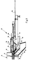
- FIGS. 1 to 4 show partially cut Side views of a tapping device 10 in different Operating positions when opening and closing a tap opening 12 of a furnace 14 of a waste incineration plant. With appropriate dimensioning can the tapping device 10 also in foundries and Steelworks for opening and closing of similar designed tap openings on blast furnaces become.
- the tapping device 10 has two approximately parallel to the longitudinal direction of the tap opening 12, in Cross-section U-shaped carrier 16, which are at a distance run to each other and from which in FIGS. 1 to 4 For reasons of clarity, only those in the background arranged carrier 16 is shown.
- the carriers 16 are on a hopper 18 provided on the furnace 14 attached, which is arranged under the tap opening 12 and through which emerges from the tap opening 12 Melt, for example, in a mold 20 (see FIG. 2) can be directed.
- the two supports 16 rest on opposite end sections a transverse to this first I-beam 22, to which they are attached.
- Towards the hopper 18 a second I-beam 24 is arranged offset between the two beams 16 extends transversely to these and is firmly connected to them.
- a carriage 28 is guided through two pairs of rollers 30 and 32 on top of the horizontally extending legs of the two supports 16 rolls off. Close to that shown on the right in FIGS. 1 to 4 A pair of connecting elements 34 is provided for the roller pair 32 firmly connected to the piston of a hydraulic cylinder 36 is.
- the hydraulic cylinder 36 is with its in FIG. 1 to 4 end shown on the left on a swivel mount 38 pivoted, the middle between the carriers 16 am second I-beam 24 is attached.
- a stuffing head 40 in which several Cooling channels (not shown) are formed, which a cooling water supply is connected.
- the stuffing head 40 is one in the longitudinal direction of the carriage 28 extending through bore 42 formed into the extending at an angle to the through bore 42
- Supply channel 44 opens.
- a feed cylinder 46 is inserted in the a piston 48 slidably mounted and with the help of a hydraulic cylinder 50 is movable.
- the stuffing head 40 is divided along the through hole 42, is with Using two interlocks (not shown) held together and can be added later explanatory purpose.
- a support element 52 In the middle of the carriage 28 is a support element 52 provided on which the rear pair of rollers 32 is rotatable is stored.
- the carrier element 52 has a slide bearing 54, whose axis of symmetry with the axis of symmetry Through hole 42 of the stuffing head 40 coincides.
- a linkage 56 In the slide bearing 54 is a linkage 56 one Rotary hammer mill 58 of a feed unit 60 rotatable and slidably mounted.
- the hammer mill 58 of the Feed unit 60 is attached to a slide 62 which with the help of two on the side of the hammer mill 58 arranged, pneumatic feed cylinder 64 in the longitudinal direction the carriage 28 between a starting position near the end of FIGS. 1 to 4 shown on the right Wagens 28, and an end position in which the Slider 62 is arranged near the slide bearing 54.
- the im Feed cylinder 64 shown in the background is shown.
- a coupling head 66 is attached at the free end of the linkage 56, left in Figs. 1 to 4 shown. With the Coupling head 66 is a coupling end 68 of a first Lance 70 coupled, the other end partially in the Through bore 42 of the stuffing head 40 protrudes.
- the first Lance 70 has a cooling channel through it Connections 72 near the coupling end 68 to one Cooling water supply can be connected. Further is on the carriage 28 an extending in the longitudinal direction Coupling hook 74 pivotally mounted, the purpose of which later will be explained later.
- the tapping device has a further functional unit 10 near the filling funnel 18 an extractor 76 on.
- the pull-out device 76 comprises a on the carrier 16 attached frame 78 with an approximately parallel to the Direction of movement of the carriage 28 along the beams 16 extending guide bar 80.
- On the guide bar 80 is a bracket 82 slidably held around the Guide bar 80 between a stop position in which the Bracket 82 is aligned with the tap hole 12, and a release position in which the Bracket 82 is pivoted backwards from the carrier 16. In the operating state shown in Fig.
- bracket 82 in which the Bracket 82 is pivoted into its holding position is on the bracket 82 is identical to the first lance 70 trained second lance 84 coupled into the Tap hole 12 of the furnace 14 is inserted and the Tap hole 12 closes.
- the second lance 84 to the cooling water supply (not shown) connected.
- bracket 82 On the bracket 82 is also a parallel Driver hook 86 protruding from the guide bar 80 provided to the coupling hook 74 of the carriage 28th is aligned when the holder 82 in its in Fig. 1st shown stop position is pivoted.
- the beam deflecting plate 88 has at its near the Tap opening 12 arranged approximately vertically extending End an opening 90, the diameter of which is so dimensioned is that the stuffing head 40 is frustoconical in shape designed area through the opening 90 can protrude through.
- a round plate 94 attached, which expanded with a cone Exit opening 96 is provided, which is concentric with Tap hole 12 of the furnace 14 is arranged.
- the plate 94 is also with both lances 70 and 84 Cooling channels (not shown) provided to the Cooling water supply are connected.
- the stuffing head 40 can also be turned 180 ° around the horizontal be turned, with all machine parts above the Darning head are arranged and the stuffing mass from above 5A-D as shown. This has the Advantage that the emerging melt stream has no parts damage the tamping device and onto the jet deflection plate can be dispensed with.
- FIG. 1 Operating state is the carriage 28 in its Starting position in which the piston of the hydraulic cylinder 36 is retracted while the rear pair of rollers 32 is close the swivel mount 38 is arranged. At the same time closes the one inserted into the tap opening 12 Lance 84 the tap opening 12 and prevents this Melt escapes from the furnace 14.
- the extractor 76 coupled to the second lance 84 as fixation for lance 84.
- the tapping device is opened before the tap opening 12 10 for closing the tap opening 12 prepared.
- the hopper is first 18 with a quick hardening stuffing compound filled.
- the cooling water supply to those coupled to the feed unit 60 first lance 70 connected and the first lance 70 chilled.
- the tap opening 12 of the furnace 14 should be opened first, with the help of the hydraulic cylinder 36 the carriage 28 in the direction of the tap hole 12 so far moved until the coupling hook 74 with the catch hook 86 of the puller 76 comes into engagement.
- the carriage 28 is then driven by the hydraulic cylinder 36 moved back to its starting position, the one engaging with the catch hook 86 Coupling hook 74 the bracket 82 along the Pulls guide bar 80.
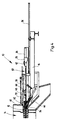
- This will bring the to the Bracket 82 coupled second lance 84 from the Tapping opening 12 drawn, as shown in Fig. 2.
- the Actuator the beam deflector plate 88 from the tap hole 12 away and releases the hopper 18. Under the In the meantime, the filling mold 18 became the mold 20 positioned into which the tap opening 12 escaping melt flows.
- the carriage 28 together with the beam deflection plate 88 the tap opening 12 moves too.
- the Hydraulic cylinder 36 is extended until the Darning head 40 with its frustoconical head portion at least partially in the conical outlet opening 96 of the plate 94 is received, as in FIG. 3 shown.
- the hydraulic cylinder 50 of the feed cylinder 46 is switched on by the Piston 48 in the direction of the through bore 42 emotional.
- the one contained in the feed cylinder 46 Darning mass through the supply channel 44 and you Through hole 42 pressed into tap hole 12, as shown in Fig. 3.
- the second lance 84 was released from the bracket 82 of the pull-out device 76 and the holder 82 coupled to the coupling end 86 of the first lance 70.
- the second lance 84 can, if it is still reusable is in the meantime cleaned stuffing head 40 inserted and with the coupling head 66 of the hammer drill 58 can be coupled.
- the carriage 28 is again in its starting position retracted so that the tapping device 10 again in their starting position shown in FIG. 1 located.
- a Stuffing head 40 is used, on which the feed cylinder 86th is attached.
- a supply line connect for example with the help a volumetric pump the stuffing head 40 Darning can be fed.
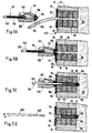
- 5A-D is the sequence of the tamping process after The method according to the invention is shown schematically.
- Melting furnace 108 contains in it through a wall 111 and 112 delimited interior a melt 110.
- the melt 110 flows through a tap opening 113 in the wall 112 as a melt stream 109 from the melting furnace 108
- the melting furnace 108 has in the region of the tap opening 113 a preferably cooled front panel 114.
- FIG. 5A To close the tap opening 113 retracts Darning head 101 against the melt jet 109, FIG. 5A.
- a wooden plug 115 is arranged, the first to prevent premature Solidification of the melt into the tap opening 113 5B. Then the by the Stuffing head 101 fed stuffing compound 107 into the tap opening 113 pressed.
- a lance 102 is replaced by a continuous longitudinal bore in the housing 105 of the stuffing head 101 in the tap opening 1113, Fig. 5C.
- the Lance 102 preferably consists of an elongated one cooled lance body 103, on the front end 103 'one closed at its end facing the furnace Sleeve 104 is attached.
- the lance 103 Darning 107 and the wooden plug 115 partially up to the melt 110 pressed in.
- the wooden plug 115 then burns in the melt 110.
- the lance 103 extends over the entire length when inserted Length of tap opening 113, preferably protrudes front tip of the sleeve 104 into the melt 110. Um to keep the furnace closed, the lance 103 mechanically secured.
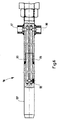
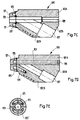
- Figure 6 shows a partially sectioned side view a lance 116 with an elongated lance main body 137.
- the lance main body 137 has a cooling channel 119 on, essentially along the longitudinal axis of the lance 116 runs and extends over about 2/3 of the total length of the Lance extends.
- To implement a cooling circuit are two connections 117, 118 for the supply and discharge provided by cooling water.
- the length of the lance is preferably 180-250 cm. Its diameter is preferably 30-50 mm.
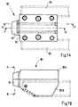
- Figures 7A-E are different views of a Darning head 120 shown.
- Figures 7A and 7B show the Top view from above or from the side.
- characters 7C, 7D and 7E show sections along the lines J-K (Fig. 7C), G-H (Fig. 7D) and A-B (Fig. 7E).
- the stuffing head 120 is on two rails 123, 124 to one Tap opening of a melting furnace, not shown here can be moved up so that its front plate 121 is form-fitting closes with the wall of the furnace.
- the housing of the Darning head 120 has a continuous longitudinal bore 128, 129 for pushing a lance in and out.
- On Supply channel 127 for stuffing material opens into the furnace Area of the longitudinal bore 128 into the through bore 129 the front plate 121.
- Cooling channels 125, 125 ' arranged to cool the Stuffing head 120, in particular its the melt stream exposed front plate 121, to a cooling circuit can be connected (connection 126).
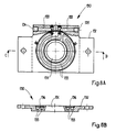
- FIGS. 8A and 8B show the front plate 130 of a melting furnace in a partially sectioned view from the front (Fig. 8A) or in cross section along the line C-D.
- the front plate 130 has a round central bore 131 on, concentric with the tap hole of a furnace is arranged. A runs around the center bore 131 Cooling channel 133, which via connections 134, 135 to one Cooling circuit can be connected.
- the cooling channel 133 is by notches in the flat body 132 of the Front plate 130 formed with an annular Disc 136 are covered.
Landscapes
- Engineering & Computer Science (AREA)
- Chemical & Material Sciences (AREA)
- Mechanical Engineering (AREA)
- Materials Engineering (AREA)
- Metallurgy (AREA)
- Organic Chemistry (AREA)
- Manufacturing & Machinery (AREA)
- General Engineering & Computer Science (AREA)
- Furnace Charging Or Discharging (AREA)
- Gasification And Melting Of Waste (AREA)
- Processing Of Solid Wastes (AREA)
- Carbon Steel Or Casting Steel Manufacturing (AREA)
- Vertical, Hearth, Or Arc Furnaces (AREA)
Abstract
Description
- Fig. 1
- eine teilweise geschnittene Seitenansicht einer erfindungsgemässen Abstichvorrichtung bei geschlossener Abstichöffnung eines Schmelzofens,
- Fig. 2
- eine teilweise geschnittene Seitenansicht der Abstichvorrichtung nach Fig. 1 unmittelbar nach dem Öffnen der Abstichöffnung,
- Fig. 3
- eine teilweise geschnittene Seitenansicht der Abstichvorrichtung nach Fig. 1 beim Befüllen der Abstichöffnung mit einer Stopfmasse, und
- Fig. 4
- eine teilweise geschnittene Seitenansicht der Abstichvorrichtung nach Fig. 1 nach dem Einführen einer die Abstichöffnung verschliessenden Lanze;
- Fig. 5A-D
- eine geschnittene Seitenansicht eines Stopfkopfes mit Stopfmasse und Lanze sowie eines Schmelzofens zur Darstellung verschiedener Stadien des erfindungsgemässen Verfahrens;
- Fig. 6
- eine teilweise geschnittene Seitenansicht einer Lanze;
- Fig. 7A-E
- verschiedene Ansichten eines Stopfkopfes mit Kühlung;
- Fig. 8A,B
- verschiedene Ansichten einer Frontplatte mit Kühlung.
Claims (16)
- Abstichvorrichtung für einen Schmelzofen, mit einer verfahrbaren Fülleinrichtung (46) zum Füllen einer offenen Abstichöffnung (12, 113) an dem Schmelzofen (14, 108) mit einer Stopfmasse (107) und mit einer verfahrbaren Stopfeinrichtung (40) zum Einführen einer Lanze (70, 84, 102, 116) in die Abstichöffnung (12, 113), wobei die Stopfeinrichtung einen Stopfkopf (40, 101, 120) aufweist, in dem eine Durchgangsbohrung (42, 129) zum Einführen der Lanze (70, 84, 102, 116) in die Abstichöffnung (12, 113) ausgebildet ist, dadurch gekennzeichnet, dass die Lanze (70, 84, 102, 116) kühlbar ist.
- Abstichvorrichtung nach Anspruch 1, dadurch gekennzeichnet, dass die Lanze (70, 84, 102, 116) eine vorzugsweise aus Kupfer oder einer Kupferlegierung gefertigte Lanze (70, 84, 102, 137) mit mindestens einem Kühlkanal (119) ist, der an eine Kühlwasserversorgung anschliessbar ist.
- Abstichvorrichtung nach einem der vorhergehenden Ansprüche, dadurch gekennzeichnet, dass eine vorzugsweise aus Kupfer gefertigte Frontplatte (94, 114, 130) mit einer Austrittsöffnung (96, 131), die mit ihrer Austrittsöffnung (96, 131) konzentrisch zur Abstichöffnung (12, 113) am Schmelzofen (14, 108) befestigbar ist und an der die Stopfeinrichtung (40) beim Einführen der Lanze (70, 84, 102, 116) in die Abstichöffnung (12, 113) ansetzbar ist.
- Abstichvorrichtung nach Anspruch 3, dadurch gekennzeichnet, dass die Frontplatte (94, 114, 130) kühlbar ist, vorzugsweise indem sie mindestens einen Kühlkanal (133) aufweist, der an eine Kühlwasserversorgung anschliessbar ist.
- Abstichvorrichtung nach einem der vorhergehenden Ansprüche, dadurch gekennzeichnet, dass der Stopfkopf (49, 101, 120) kühlbar ist, vorzugsweise indem er mindestens einen Kühlkanal (125, 125') aufweist, der an eine Kühlwasserversorgung anschliessbar ist.
- Abstichvorrichtung nach einem der vorhergehenden Ansprüche, dadurch gekennzeichnet, dass in dem Stopfkopf (40, 101, 120) ein in die Durchgangsbohrung (42, 129) mündender Versorgungskanal (44, 127) ausgebildet ist, der zum Einleiten der Stopfmasse (107) in die Durchgangsbohrung (42, 129) mit der Fülleinrichtung (46) derart verbunden ist, dass die Stopfmasse (107) zum Füllen der Abstichöffnung (12, 113) durch den Versorgungskanal (44, 127) und die Durchgangsbohrung (42, 129) in die Abstichöffnung (12, 113) gelangt.
- Abstichvorrichtung nach Anspruch 6, dadurch gekennzeichnet, dass die Durchgangsbohrung (42, 129) vor dem Füllen der Abstichöffnung (12, 113) mit einem Holzstopfen (115) verschlossen ist, welcher beim Füllen von der Stopfmasse (107) in die Abstichöffnung (12, 113) hineingeschoben wird.
- Abstichvorrichtung nach einem der vorhergehenden Ansprüche, dadurch gekennzeichnet, dass die Lanze (70, 84, 102, 116) eine Hülse (104) aufweist, die an ihrem der Abstichöffnung (12, 113) zugewandten Ende (103') aufgesetzt ist und die aus einem Material mit geringerem Schmelzpunkt als dem der im Schmelzofen (14, 108) enthaltenen Schmelze (110) besteht, vorzugsweise aus Kupfer oder einer Kupferlegierung.
- Abstichvorrichtung nach Anspruch 7, dadurch gekennzeichnet, dass die Reibung zwischen der Lanze (70, 84, 102, 116) und der Hülse (104) derart ist, dass die Hülse (104) beim Herausziehen der Lanze (70, 84, 102, 116) in der Abstichöffnung (12, 113) verbleibt.
- Lanze (70, 84, 102, 116) zum Verschliessen und Öffnen der Abstichöffnung (12, 113) eines Schmelzofens (14, 108), dadurch gekennzeichnet, dass die Lanze (70, 84, 102, 116) wenigstens einen Kühlkanal (119) aufweist, der an eine Kühlwasserversorgung anschliessbar ist.
- Lanze (70, 84, 102, 116) nach Anspruch 10, dadurch gekennzeichnet, dass die Lanze (70, 84, 102, 116) eine Hülse (104) aufweist, die an ihrem der Abstichöffnung (12, 113) zugewandten Ende (103') aufgesetzt ist und die aus einem Material mit geringerem Schmelzpunkt als dem der im Schmelzofen (14, 108) enthaltenen Schmelze (110) besteht, vorzugsweise aus Kupfer oder einer Kupferlegierung.
- Lanze (70, 84, 102, 116) nach Anspruch 11, dadurch gekennzeichnet, dass die Reibung zwischen der Lanze (70, 84, 102, 116) und der Hülse (104) derart ist, dass die Hülse (104) beim Herausziehen der Lanze (70, 84, 102, 116) in der Abstichöffnung (12, 113) verbleibt.
- Abstichverfahren für einen Schmelzofen (14, 108), bei dem zum Verschliessen einer offenen Abstichöffnung (12, 113) an dem Schmelzofen (14, 108) eine Stopfmasse (107) und eine Lanze (70, 84, 102, 116) bereitgestellt, die offene Abstichöffnung (12, 113) mit der Stopfmasse (107) zumindest teilweise gefüllt und gleichzeitig oder anschliessend die Lanze (70, 84, 102, 116) in die Abstichöffnung (12, 113) eingeführt wird, dadurch gekennzeichnet, dass die Lanze (70, 84, 102, 116) gekühlt wird.
- Abstichverfahren nach Anspruch 13, bei dem die Lanze (70, 84, 102, 116), während sie in die Abstichöffnung (12, 113) eingeführt wird, die Stopfmasse (107) zumindest teilweise in die Abstichöffnung (12, 113) schiebt.
- Abstichverfahren nach Anspruch 13 oder 14, bei dem ein Holzstopfen (115) bereitgestellt wird, welcher vor der Stopfmasse (107) in die Abstichöffnung (12, 113) eingeführt und durch diese hindurchgeschoben wird, vorzugsweise indem er von der Stopfmasse (107) geschoben wird.
- Verfahren nach Anspruch 13, 14 oder 15, bei welchem auf das der Abstichöffnung (12, 113) zugewandte Ende (103') der Lanze (70, 84, 102, 116) eine Hülse (104) aufgesetzt wird, die aus einem Material mit geringerem Schmelzpunkt als dem der im Schmelzofen (14, 108) enthaltenen Schmelze besteht, vorzugsweise aus Kupfer oder einer Kupferlegierung, wobei die Lanze (70, 84, 102, 116) mit der Hülse (104) in die Abstichöffnung (12, 113) eingeführt wird und die Hülse (104) beim Herausziehen der Lanze (70, 84, 102, 116) in der Abstichöffnung (12, 113) verbleibt.
Applications Claiming Priority (2)
| Application Number | Priority Date | Filing Date | Title |
|---|---|---|---|
| CH124599 | 1999-07-07 | ||
| CH124599 | 1999-07-07 |
Publications (2)
| Publication Number | Publication Date |
|---|---|
| EP1069191A1 true EP1069191A1 (de) | 2001-01-17 |
| EP1069191B1 EP1069191B1 (de) | 2005-09-28 |
Family
ID=4205878
Family Applications (1)
| Application Number | Title | Priority Date | Filing Date |
|---|---|---|---|
| EP20000113436 Expired - Lifetime EP1069191B1 (de) | 1999-07-07 | 2000-06-24 | Abstichvorrichtung sowie Abstichverfahren |
Country Status (3)
| Country | Link |
|---|---|
| EP (1) | EP1069191B1 (de) |
| JP (1) | JP2001056185A (de) |
| DE (1) | DE50011237D1 (de) |
Cited By (4)
| Publication number | Priority date | Publication date | Assignee | Title |
|---|---|---|---|---|
| EP1233077A1 (de) * | 2001-02-15 | 2002-08-21 | Productos Refractarios Asturianos Para La Siderurgia, S.A. | Reparatursystem der Auskleidung einer Hochofenabstichöffnung |
| US10844466B2 (en) | 2015-10-19 | 2020-11-24 | Nippon Steel Corporation | Hot forging steel and hot forged product |
| CN112857052A (zh) * | 2021-02-01 | 2021-05-28 | 琪玥环保设备(唐山)有限公司 | 一种堵孔装置及具有其的等离子体炉 |
| WO2022233414A1 (de) * | 2021-05-06 | 2022-11-10 | Tmt Tapping Measuring Technology Sàrl | Sauerstofflanzenführungsanordnung |
Families Citing this family (1)
| Publication number | Priority date | Publication date | Assignee | Title |
|---|---|---|---|---|
| CN105698541B (zh) * | 2015-12-31 | 2018-05-18 | 遵义伟明铝业有限公司 | 一种熔铝炉出料口的封口装置 |
Citations (9)
| Publication number | Priority date | Publication date | Assignee | Title |
|---|---|---|---|---|
| US2294162A (en) * | 1942-08-25 | Blast furnace cinder notch stopper | ||
| JPS52150703A (en) * | 1976-06-11 | 1977-12-14 | Nippon Steel Corp | Tap hole opening in blast furnace |
| JPS5585609A (en) * | 1978-12-21 | 1980-06-27 | Nippon Steel Corp | Boring method for tap hole of blast furnace |
| JPS5690906A (en) * | 1979-12-24 | 1981-07-23 | Kawasaki Steel Corp | Temperature controlling method of mud for closing iron notch |
| DD258721A3 (de) * | 1986-03-26 | 1988-08-03 | Funk A Bergbau Huettenkombinat | Verfahren und vorrichtung zum schliessen einer abstichoeffnung |
| DD259760A3 (de) * | 1988-06-18 | 1988-09-07 | Funk A Bergbau Huettenkombinat | Einrichtung zum schliessen einer abstichoeffnung |
| US4909487A (en) * | 1988-02-03 | 1990-03-20 | Dango & Dienenthal Maschinenbau Gmbh | Process and notch gun for closing the tapholes of furnaces |
| FR2680179A1 (fr) * | 1991-08-07 | 1993-02-12 | Boulonnais Terres Refractaires | Perfectionnements apportes aux dispositifs de bouchage de trous de coulee de hauts-fourneaux. |
| US5511768A (en) * | 1994-01-17 | 1996-04-30 | Paul Wurth S.A. | Tap hole plugging device |
-
2000
- 2000-06-24 DE DE50011237T patent/DE50011237D1/de not_active Expired - Fee Related
- 2000-06-24 EP EP20000113436 patent/EP1069191B1/de not_active Expired - Lifetime
- 2000-07-07 JP JP2000206591A patent/JP2001056185A/ja active Pending
Patent Citations (9)
| Publication number | Priority date | Publication date | Assignee | Title |
|---|---|---|---|---|
| US2294162A (en) * | 1942-08-25 | Blast furnace cinder notch stopper | ||
| JPS52150703A (en) * | 1976-06-11 | 1977-12-14 | Nippon Steel Corp | Tap hole opening in blast furnace |
| JPS5585609A (en) * | 1978-12-21 | 1980-06-27 | Nippon Steel Corp | Boring method for tap hole of blast furnace |
| JPS5690906A (en) * | 1979-12-24 | 1981-07-23 | Kawasaki Steel Corp | Temperature controlling method of mud for closing iron notch |
| DD258721A3 (de) * | 1986-03-26 | 1988-08-03 | Funk A Bergbau Huettenkombinat | Verfahren und vorrichtung zum schliessen einer abstichoeffnung |
| US4909487A (en) * | 1988-02-03 | 1990-03-20 | Dango & Dienenthal Maschinenbau Gmbh | Process and notch gun for closing the tapholes of furnaces |
| DD259760A3 (de) * | 1988-06-18 | 1988-09-07 | Funk A Bergbau Huettenkombinat | Einrichtung zum schliessen einer abstichoeffnung |
| FR2680179A1 (fr) * | 1991-08-07 | 1993-02-12 | Boulonnais Terres Refractaires | Perfectionnements apportes aux dispositifs de bouchage de trous de coulee de hauts-fourneaux. |
| US5511768A (en) * | 1994-01-17 | 1996-04-30 | Paul Wurth S.A. | Tap hole plugging device |
Non-Patent Citations (3)
| Title |
|---|
| PATENT ABSTRACTS OF JAPAN vol. 002, no. 043 (C - 008) 23 March 1978 (1978-03-23) * |
| PATENT ABSTRACTS OF JAPAN vol. 004, no. 135 (C - 025) 20 September 1980 (1980-09-20) * |
| PATENT ABSTRACTS OF JAPAN vol. 005, no. 160 (C - 075) 15 October 1981 (1981-10-15) * |
Cited By (5)
| Publication number | Priority date | Publication date | Assignee | Title |
|---|---|---|---|---|
| EP1233077A1 (de) * | 2001-02-15 | 2002-08-21 | Productos Refractarios Asturianos Para La Siderurgia, S.A. | Reparatursystem der Auskleidung einer Hochofenabstichöffnung |
| US10844466B2 (en) | 2015-10-19 | 2020-11-24 | Nippon Steel Corporation | Hot forging steel and hot forged product |
| CN112857052A (zh) * | 2021-02-01 | 2021-05-28 | 琪玥环保设备(唐山)有限公司 | 一种堵孔装置及具有其的等离子体炉 |
| WO2022233414A1 (de) * | 2021-05-06 | 2022-11-10 | Tmt Tapping Measuring Technology Sàrl | Sauerstofflanzenführungsanordnung |
| US12595964B2 (en) | 2021-05-06 | 2026-04-07 | Tmt Tapping Measuring Technology Sarl | Oxygen lance guiding assembly |
Also Published As
| Publication number | Publication date |
|---|---|
| EP1069191B1 (de) | 2005-09-28 |
| JP2001056185A (ja) | 2001-02-27 |
| DE50011237D1 (de) | 2005-11-03 |
Similar Documents
| Publication | Publication Date | Title |
|---|---|---|
| EP2663413B1 (de) | Giessrohrwechsler mit blindplatte für eine giessvorrichtung zum erzeugen metallurgischer produkte | |
| DE3145100A1 (de) | "fuehrungs- und supportkopf fuer abstichlochschlagstangen bei schachtoefen, sowie mit einem solchen kopf versehene bohrmaschine" | |
| DE2630232C2 (de) | Automatische Abstichmaschine für den Abstich bei elektrischen Hochöfen und Öfen für die Herstellung von Legierungen o.dgl. | |
| DE2912295C2 (de) | Verfahren zur Reparatur des Abstichlochs eines Konverters | |
| EP2226176B1 (de) | Verfahren und Vorrichtung zur Herstellung eines Kunststoffteils | |
| EP0819488B1 (de) | Schiebeverschluss für einen Metallschmelze enthaltenden Behälter | |
| EP0727268A2 (de) | Schiebeverschluss für einen Metallschmelze enthaltenden Behälter | |
| EP0428661B1 (de) | Einrichtung zum entfernen von verschlissenen lochsteinen oder lochauskleidungen metallurgischer gefässe | |
| EP1069191B1 (de) | Abstichvorrichtung sowie Abstichverfahren | |
| DE2317663A1 (de) | Vorrichtung zur steuerung des ausflusses der metallschmelze aus einem schmelzgutbehaelter | |
| DE1903475A1 (de) | Verfahren und Vorrichtung zum Vorbohren und Abschaelen von Barren zum nachfolgenden Extrudieren | |
| DE1758681A1 (de) | Vorrichtung und Verfahren zum Vergiessen von Metallen | |
| DE10025341B4 (de) | Sickersystem für eine Spritzgiessvorrichtung | |
| DE3443143A1 (de) | Verfahren und vorrichtung zum oeffnen und schliessen eines stichloches an oefen | |
| EP0974801A1 (de) | Verfahren und Einrichtung zum schlackefreien Abstechen | |
| DE4492636C2 (de) | Abstichloch und Verfahren zur Bildung eines Abflusskanals eines Abstichlochs | |
| CH643020A5 (de) | Verfahren und vorrichtung zum wiederausrichten von schienenstraengen. | |
| EP3851225A1 (de) | Schiebeverschluss für ein metallurgisches gefäss | |
| DE2120670A1 (de) | Verfahren und Vorrichtung zum Ausstoßen des Walzstopfens für Walzwerke | |
| EP1172162A1 (de) | Verfahren und Verschliessen oder Öffnen des Abstichloches eines metallurgischen Gefässes, insbesondere eines Elektrolichtbogenofens und zugehöriger Bodenabstich | |
| DE3444513A1 (de) | Einblasstein mit einem den einblaskanal des einblassteins abdeckenden verschlussstein fuer metallurgische gefaesse, insbesondere stahlpfannen, zum einblasen von gasen bzw. feststoff/gas-gemischen in in den metallurgischen gefaessen befindliche metallische schmelzen | |
| DE3201633A1 (de) | Anlage zum horizontalen stranggiessen von metallen, insbesondere von stahl | |
| WO2005024069A2 (de) | Abstichvorrichtung für ein schmelzgefäss, insbesondere für einen konverter | |
| EP1577036B1 (de) | Dosiervorrichtung für eine Schmelze | |
| DE10200852B4 (de) | Vorrichtung zum Vorsehen einer Reihe nebeneinander angeordneter Einbauelemente in einer nicht ausgehärteten Betonlage |
Legal Events
| Date | Code | Title | Description |
|---|---|---|---|
| PUAI | Public reference made under article 153(3) epc to a published international application that has entered the european phase |
Free format text: ORIGINAL CODE: 0009012 |
|
| AK | Designated contracting states |
Kind code of ref document: A1 Designated state(s): CH DE FR LI NL |
|
| AX | Request for extension of the european patent |
Free format text: AL;LT;LV;MK;RO;SI |
|
| 17P | Request for examination filed |
Effective date: 20010210 |
|
| AKX | Designation fees paid |
Free format text: CH DE FR LI NL |
|
| 17Q | First examination report despatched |
Effective date: 20031125 |
|
| GRAP | Despatch of communication of intention to grant a patent |
Free format text: ORIGINAL CODE: EPIDOSNIGR1 |
|
| GRAS | Grant fee paid |
Free format text: ORIGINAL CODE: EPIDOSNIGR3 |
|
| GRAA | (expected) grant |
Free format text: ORIGINAL CODE: 0009210 |
|
| AK | Designated contracting states |
Kind code of ref document: B1 Designated state(s): CH DE FR LI NL |
|
| PG25 | Lapsed in a contracting state [announced via postgrant information from national office to epo] |
Ref country code: NL Free format text: LAPSE BECAUSE OF FAILURE TO SUBMIT A TRANSLATION OF THE DESCRIPTION OR TO PAY THE FEE WITHIN THE PRESCRIBED TIME-LIMIT Effective date: 20050928 |
|
| REG | Reference to a national code |
Ref country code: CH Ref legal event code: EP Ref country code: CH Ref legal event code: NV Representative=s name: PATENTANWAELTE SCHAAD, BALASS, MENZL & PARTNER AG |
|
| REF | Corresponds to: |
Ref document number: 50011237 Country of ref document: DE Date of ref document: 20051103 Kind code of ref document: P |
|
| NLV1 | Nl: lapsed or annulled due to failure to fulfill the requirements of art. 29p and 29m of the patents act | ||
| ET | Fr: translation filed | ||
| PG25 | Lapsed in a contracting state [announced via postgrant information from national office to epo] |
Ref country code: LI Free format text: LAPSE BECAUSE OF NON-PAYMENT OF DUE FEES Effective date: 20060630 Ref country code: CH Free format text: LAPSE BECAUSE OF NON-PAYMENT OF DUE FEES Effective date: 20060630 |
|
| PLBE | No opposition filed within time limit |
Free format text: ORIGINAL CODE: 0009261 |
|
| STAA | Information on the status of an ep patent application or granted ep patent |
Free format text: STATUS: NO OPPOSITION FILED WITHIN TIME LIMIT |
|
| 26N | No opposition filed |
Effective date: 20060629 |
|
| PG25 | Lapsed in a contracting state [announced via postgrant information from national office to epo] |
Ref country code: DE Free format text: LAPSE BECAUSE OF NON-PAYMENT OF DUE FEES Effective date: 20070103 |
|
| REG | Reference to a national code |
Ref country code: CH Ref legal event code: PL |
|
| REG | Reference to a national code |
Ref country code: FR Ref legal event code: ST Effective date: 20070228 |
|
| PG25 | Lapsed in a contracting state [announced via postgrant information from national office to epo] |
Ref country code: FR Free format text: LAPSE BECAUSE OF NON-PAYMENT OF DUE FEES Effective date: 20060630 |