EP1069191A1 - Tapping apparatus and method - Google Patents
Tapping apparatus and method Download PDFInfo
- Publication number
- EP1069191A1 EP1069191A1 EP00113436A EP00113436A EP1069191A1 EP 1069191 A1 EP1069191 A1 EP 1069191A1 EP 00113436 A EP00113436 A EP 00113436A EP 00113436 A EP00113436 A EP 00113436A EP 1069191 A1 EP1069191 A1 EP 1069191A1
- Authority
- EP
- European Patent Office
- Prior art keywords
- lance
- tap
- stuffing
- opening
- hole
- Prior art date
- Legal status (The legal status is an assumption and is not a legal conclusion. Google has not performed a legal analysis and makes no representation as to the accuracy of the status listed.)
- Granted
Links
- 238000010079 rubber tapping Methods 0.000 title claims abstract description 52
- 238000000034 method Methods 0.000 title claims abstract description 12
- 238000001816 cooling Methods 0.000 claims abstract description 25
- 239000000498 cooling water Substances 0.000 claims abstract description 12
- RYGMFSIKBFXOCR-UHFFFAOYSA-N Copper Chemical compound [Cu] RYGMFSIKBFXOCR-UHFFFAOYSA-N 0.000 claims abstract description 9
- 229910052802 copper Inorganic materials 0.000 claims abstract description 9
- 239000010949 copper Substances 0.000 claims abstract description 9
- 239000000463 material Substances 0.000 claims abstract description 9
- 229910000881 Cu alloy Inorganic materials 0.000 claims abstract description 7
- 238000002844 melting Methods 0.000 claims description 35
- 230000008018 melting Effects 0.000 claims description 35
- 150000001875 compounds Chemical class 0.000 claims description 3
- 238000003780 insertion Methods 0.000 claims description 3
- 230000037431 insertion Effects 0.000 claims description 3
- 239000000155 melt Substances 0.000 description 20
- 230000008878 coupling Effects 0.000 description 12
- 238000010168 coupling process Methods 0.000 description 12
- 238000005859 coupling reaction Methods 0.000 description 12
- 230000033001 locomotion Effects 0.000 description 10
- 238000011161 development Methods 0.000 description 4
- 230000018109 developmental process Effects 0.000 description 4
- 239000000969 carrier Substances 0.000 description 3
- 230000000694 effects Effects 0.000 description 3
- 238000004056 waste incineration Methods 0.000 description 3
- 239000007789 gas Substances 0.000 description 2
- 230000001174 ascending effect Effects 0.000 description 1
- 238000004140 cleaning Methods 0.000 description 1
- 238000002485 combustion reaction Methods 0.000 description 1
- 239000004020 conductor Substances 0.000 description 1
- 238000010276 construction Methods 0.000 description 1
- 230000007423 decrease Effects 0.000 description 1
- 230000002996 emotional effect Effects 0.000 description 1
- 230000007613 environmental effect Effects 0.000 description 1
- 230000017525 heat dissipation Effects 0.000 description 1
- 230000002706 hydrostatic effect Effects 0.000 description 1
- 230000010354 integration Effects 0.000 description 1
- 239000002184 metal Substances 0.000 description 1
- 229910052751 metal Inorganic materials 0.000 description 1
- 230000002028 premature Effects 0.000 description 1
- 239000011819 refractory material Substances 0.000 description 1
- 230000000630 rising effect Effects 0.000 description 1
- 238000007789 sealing Methods 0.000 description 1
- 238000007711 solidification Methods 0.000 description 1
- 230000008023 solidification Effects 0.000 description 1
- XLYOFNOQVPJJNP-UHFFFAOYSA-N water Substances O XLYOFNOQVPJJNP-UHFFFAOYSA-N 0.000 description 1
Images


Classifications
-
- C—CHEMISTRY; METALLURGY
- C21—METALLURGY OF IRON
- C21B—MANUFACTURE OF IRON OR STEEL
- C21B7/00—Blast furnaces
- C21B7/12—Opening or sealing the tap holes
-
- F—MECHANICAL ENGINEERING; LIGHTING; HEATING; WEAPONS; BLASTING
- F27—FURNACES; KILNS; OVENS; RETORTS
- F27D—DETAILS OR ACCESSORIES OF FURNACES, KILNS, OVENS OR RETORTS, IN SO FAR AS THEY ARE OF KINDS OCCURRING IN MORE THAN ONE KIND OF FURNACE
- F27D3/00—Charging; Discharging; Manipulation of charge
- F27D3/15—Tapping equipment; Equipment for removing or retaining slag
- F27D3/1509—Tapping equipment
- F27D3/1536—Devices for plugging tap holes, e.g. plugs stoppers
Definitions
- the invention relates to a tapping device for a Melting furnace according to the preamble of claim 1 and a lance to close and open the tap hole a melting furnace.
- the invention further relates to a Tapping process for a melting furnace according to the Preamble of claim 14.
- GB 2 285 675 is a generic tapping device with a filling device for filling the open tap hole with a stuffing and one movable tamping device for inserting a lance into the tap opening is known.
- the lance a simple one elongated rod, is under impact and Vibrations introduced into the tap hole after the stuffing has been filled in, e.g. with help of a Hammer, and remains there until reopened the tap opening by pulling out the lance.
- DE 3 803 132 A1 describes a tapping device known in which a to close the tap hole Pressed in stuffing and at the same time one to Tapping the furnace into the lance remaining in the tap hole Stuffing is introduced.
- the tapping device a stuffing head with a through hole through which both the stuffing and the lance is inserted into the tap hole.
- Minimum wall thickness necessary which is usually above the Wall thickness in the remaining areas of the melting furnace lies. This wall thickness is usually in the range of about 600-800 mm. It requires a minimum size of the Melting furnace and a minimum space requirement, in particular in waste incineration plants often over the available space.
- the task is solved with a tapping device the features of claim 1, by a tapping process with the features of claim 13 and by a coolable Lance with the features of claim 10.
- the open tap hole is first opened using the Filling device filled with the stuffing. As soon as the Stuffing was pressed in, but at the latest after a few seconds, the tamping device guides the lance in the tap hole. Alternatively, the lance be introduced simultaneously with the stuffing. In Both cases will be part of the tap opening from the lance into the Tap hole pressed. By acting in the furnace Heat hardens the stuffing. The in the tap hole The inserted lance is mechanically secured from the outside. The lance is pulled to open the tap hole. This is done by the one in the furnace Melt caused hydrostatic pressure to still build in the tamping material from the tap opening pressed so that the melt unhindered from the Can flow through the tap opening.
- the tap hole is closed again by the Filling device again filled with stuffing and the Use the tamping device to lance into the tap hole introduced.
- a chilled lance the material in the vicinity of the tap opening also chilled. The risk of heat damage decreases, and that Lifespan and operational safety of the melting furnace elevated.
- the cooling also prevents the lance from turning on its front end melts, that of the largest Is exposed to heat. The cooling thus allows the construction of melting furnaces with a smaller wall thickness.
- the wall thickness can be from the conventional 600-800 mm to approximately that Half to a third can be reduced. So are smaller and therefore cheaper melting furnaces constructible, in particular for melting the Combustion residues in waste incineration plants are suitable.
- the lance is preferably made of copper or made of a copper alloy and with at least one Cooling channel provided that connects to a cooling water supply can be connected.
- the plate in a further preferred embodiment is before Tapping opening of the melting furnace one preferably Copper or similar thermally conductive material manufactured front panel with an outlet opening arranged, which leaves the tap opening.
- the stuffing head of the stuffing device is when inserting the Lance into the tap hole preferably with a positive fit the plate can be used as a sealing element between the tamping device and the tap opening.
- this plate can also be cooled, e.g. by means of water cooling.
- the stuffing head is also cooled, which creates the cooling effect reinforced and the heat dissipation of the lance is improved.
- the Darning head additionally on a supply channel, which in the through hole of the stuffing head opens.
- the Supply channel is connected to the filling device, which is required to close the tap hole Stuffing mass through the supply channel and Through hole in the tap hole promotes. The then inserted through the through hole Lance pushes them in the through hole and in the Tap hole contained in its final filling Position in the tap hole, creating an even Distribution of the stuffing mass around the lance in the Tap opening is guaranteed.
- the lance has a sleeve on which the Tapping hole facing end is placed.
- the sleeve consists of a material that is the same or one has a lower melting point than that in the melting furnace contained melt, preferably made of copper or a Copper alloy.
- the sleeve remains when the lance is pulled in the tap hole and is through the melt melted off so that the melt jet flow out can.
- the sleeve has the advantage of pulling the lance is simplified because its contact surface with the stuffing is reduced. The lance is therefore less damaged and can be reused.
- the sleeve is a Wear part.
- the stuffing head To insert the lance through the through hole of the A feed unit is used for the stuffing head. Through the Using the stuffing head will open the tap hole during the insertion of the lance to the outside at least partially sealed. At the same time ensures that in the stuffing head trained through hole that the lance in a defined direction of insertion into the tap hole is introduced so that any damage to the refractory material in the tap hole area be avoided.
- a suitable feed unit for the tamping device especially a rotary hammer mill or a hydraulic one Drive.
- a hammer mill can be used in addition to the Feed movement of the lance simultaneously a rotary Movement of the lance about its longitudinal axis and one Vibrating movement generated in the direction of its longitudinal axis become. Due to the combined rotation and The shaking movement is distributed in the tap opening contained stuffing particularly evenly around the lance moving into the tap hole while at the same time against the advancing movement of the lance acting forces are less than with a lance, the exclusively with an axial movement in the Tapping hole is introduced. However, on the Rotation can also be dispensed with.
- An extracting device can also be attached to the tapping device be provided for pulling out the in inserted the tap hole, closing it Lance serves.
- the tapping device is a fully automatic opening and closing the tap opening so that the Tap hole and the trough of the melting furnace together with the functional units of the tapping device in a housing closed to the outside Can be accommodated in which the melt rising gases and suspended matter and one Cleaning and filter system can be supplied.
- a suitable pull-out device is, for example a movable in the longitudinal direction of the tap opening Bracket that can be coupled to the lance.
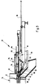
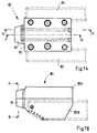
- FIGS. 1 to 4 show partially cut Side views of a tapping device 10 in different Operating positions when opening and closing a tap opening 12 of a furnace 14 of a waste incineration plant. With appropriate dimensioning can the tapping device 10 also in foundries and Steelworks for opening and closing of similar designed tap openings on blast furnaces become.
- the tapping device 10 has two approximately parallel to the longitudinal direction of the tap opening 12, in Cross-section U-shaped carrier 16, which are at a distance run to each other and from which in FIGS. 1 to 4 For reasons of clarity, only those in the background arranged carrier 16 is shown.
- the carriers 16 are on a hopper 18 provided on the furnace 14 attached, which is arranged under the tap opening 12 and through which emerges from the tap opening 12 Melt, for example, in a mold 20 (see FIG. 2) can be directed.
- the two supports 16 rest on opposite end sections a transverse to this first I-beam 22, to which they are attached.
- Towards the hopper 18 a second I-beam 24 is arranged offset between the two beams 16 extends transversely to these and is firmly connected to them.
- a carriage 28 is guided through two pairs of rollers 30 and 32 on top of the horizontally extending legs of the two supports 16 rolls off. Close to that shown on the right in FIGS. 1 to 4 A pair of connecting elements 34 is provided for the roller pair 32 firmly connected to the piston of a hydraulic cylinder 36 is.
- the hydraulic cylinder 36 is with its in FIG. 1 to 4 end shown on the left on a swivel mount 38 pivoted, the middle between the carriers 16 am second I-beam 24 is attached.
- a stuffing head 40 in which several Cooling channels (not shown) are formed, which a cooling water supply is connected.
- the stuffing head 40 is one in the longitudinal direction of the carriage 28 extending through bore 42 formed into the extending at an angle to the through bore 42
- Supply channel 44 opens.
- a feed cylinder 46 is inserted in the a piston 48 slidably mounted and with the help of a hydraulic cylinder 50 is movable.
- the stuffing head 40 is divided along the through hole 42, is with Using two interlocks (not shown) held together and can be added later explanatory purpose.
- a support element 52 In the middle of the carriage 28 is a support element 52 provided on which the rear pair of rollers 32 is rotatable is stored.
- the carrier element 52 has a slide bearing 54, whose axis of symmetry with the axis of symmetry Through hole 42 of the stuffing head 40 coincides.
- a linkage 56 In the slide bearing 54 is a linkage 56 one Rotary hammer mill 58 of a feed unit 60 rotatable and slidably mounted.
- the hammer mill 58 of the Feed unit 60 is attached to a slide 62 which with the help of two on the side of the hammer mill 58 arranged, pneumatic feed cylinder 64 in the longitudinal direction the carriage 28 between a starting position near the end of FIGS. 1 to 4 shown on the right Wagens 28, and an end position in which the Slider 62 is arranged near the slide bearing 54.
- the im Feed cylinder 64 shown in the background is shown.
- a coupling head 66 is attached at the free end of the linkage 56, left in Figs. 1 to 4 shown. With the Coupling head 66 is a coupling end 68 of a first Lance 70 coupled, the other end partially in the Through bore 42 of the stuffing head 40 protrudes.
- the first Lance 70 has a cooling channel through it Connections 72 near the coupling end 68 to one Cooling water supply can be connected. Further is on the carriage 28 an extending in the longitudinal direction Coupling hook 74 pivotally mounted, the purpose of which later will be explained later.
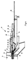
- the tapping device has a further functional unit 10 near the filling funnel 18 an extractor 76 on.
- the pull-out device 76 comprises a on the carrier 16 attached frame 78 with an approximately parallel to the Direction of movement of the carriage 28 along the beams 16 extending guide bar 80.
- On the guide bar 80 is a bracket 82 slidably held around the Guide bar 80 between a stop position in which the Bracket 82 is aligned with the tap hole 12, and a release position in which the Bracket 82 is pivoted backwards from the carrier 16. In the operating state shown in Fig.
- bracket 82 in which the Bracket 82 is pivoted into its holding position is on the bracket 82 is identical to the first lance 70 trained second lance 84 coupled into the Tap hole 12 of the furnace 14 is inserted and the Tap hole 12 closes.
- the second lance 84 to the cooling water supply (not shown) connected.
- bracket 82 On the bracket 82 is also a parallel Driver hook 86 protruding from the guide bar 80 provided to the coupling hook 74 of the carriage 28th is aligned when the holder 82 in its in Fig. 1st shown stop position is pivoted.
- the beam deflecting plate 88 has at its near the Tap opening 12 arranged approximately vertically extending End an opening 90, the diameter of which is so dimensioned is that the stuffing head 40 is frustoconical in shape designed area through the opening 90 can protrude through.
- a round plate 94 attached, which expanded with a cone Exit opening 96 is provided, which is concentric with Tap hole 12 of the furnace 14 is arranged.
- the plate 94 is also with both lances 70 and 84 Cooling channels (not shown) provided to the Cooling water supply are connected.
- the stuffing head 40 can also be turned 180 ° around the horizontal be turned, with all machine parts above the Darning head are arranged and the stuffing mass from above 5A-D as shown. This has the Advantage that the emerging melt stream has no parts damage the tamping device and onto the jet deflection plate can be dispensed with.
- FIG. 1 Operating state is the carriage 28 in its Starting position in which the piston of the hydraulic cylinder 36 is retracted while the rear pair of rollers 32 is close the swivel mount 38 is arranged. At the same time closes the one inserted into the tap opening 12 Lance 84 the tap opening 12 and prevents this Melt escapes from the furnace 14.
- the extractor 76 coupled to the second lance 84 as fixation for lance 84.
- the tapping device is opened before the tap opening 12 10 for closing the tap opening 12 prepared.
- the hopper is first 18 with a quick hardening stuffing compound filled.
- the cooling water supply to those coupled to the feed unit 60 first lance 70 connected and the first lance 70 chilled.
- the tap opening 12 of the furnace 14 should be opened first, with the help of the hydraulic cylinder 36 the carriage 28 in the direction of the tap hole 12 so far moved until the coupling hook 74 with the catch hook 86 of the puller 76 comes into engagement.
- the carriage 28 is then driven by the hydraulic cylinder 36 moved back to its starting position, the one engaging with the catch hook 86 Coupling hook 74 the bracket 82 along the Pulls guide bar 80.
- This will bring the to the Bracket 82 coupled second lance 84 from the Tapping opening 12 drawn, as shown in Fig. 2.
- the Actuator the beam deflector plate 88 from the tap hole 12 away and releases the hopper 18. Under the In the meantime, the filling mold 18 became the mold 20 positioned into which the tap opening 12 escaping melt flows.
- the carriage 28 together with the beam deflection plate 88 the tap opening 12 moves too.
- the Hydraulic cylinder 36 is extended until the Darning head 40 with its frustoconical head portion at least partially in the conical outlet opening 96 of the plate 94 is received, as in FIG. 3 shown.
- the hydraulic cylinder 50 of the feed cylinder 46 is switched on by the Piston 48 in the direction of the through bore 42 emotional.
- the one contained in the feed cylinder 46 Darning mass through the supply channel 44 and you Through hole 42 pressed into tap hole 12, as shown in Fig. 3.
- the second lance 84 was released from the bracket 82 of the pull-out device 76 and the holder 82 coupled to the coupling end 86 of the first lance 70.
- the second lance 84 can, if it is still reusable is in the meantime cleaned stuffing head 40 inserted and with the coupling head 66 of the hammer drill 58 can be coupled.
- the carriage 28 is again in its starting position retracted so that the tapping device 10 again in their starting position shown in FIG. 1 located.
- a Stuffing head 40 is used, on which the feed cylinder 86th is attached.
- a supply line connect for example with the help a volumetric pump the stuffing head 40 Darning can be fed.
- 5A-D is the sequence of the tamping process after The method according to the invention is shown schematically.
- Melting furnace 108 contains in it through a wall 111 and 112 delimited interior a melt 110.
- the melt 110 flows through a tap opening 113 in the wall 112 as a melt stream 109 from the melting furnace 108
- the melting furnace 108 has in the region of the tap opening 113 a preferably cooled front panel 114.
- FIG. 5A To close the tap opening 113 retracts Darning head 101 against the melt jet 109, FIG. 5A.
- a wooden plug 115 is arranged, the first to prevent premature Solidification of the melt into the tap opening 113 5B. Then the by the Stuffing head 101 fed stuffing compound 107 into the tap opening 113 pressed.
- a lance 102 is replaced by a continuous longitudinal bore in the housing 105 of the stuffing head 101 in the tap opening 1113, Fig. 5C.
- the Lance 102 preferably consists of an elongated one cooled lance body 103, on the front end 103 'one closed at its end facing the furnace Sleeve 104 is attached.
- the lance 103 Darning 107 and the wooden plug 115 partially up to the melt 110 pressed in.
- the wooden plug 115 then burns in the melt 110.
- the lance 103 extends over the entire length when inserted Length of tap opening 113, preferably protrudes front tip of the sleeve 104 into the melt 110. Um to keep the furnace closed, the lance 103 mechanically secured.
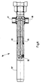
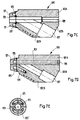
- Figure 6 shows a partially sectioned side view a lance 116 with an elongated lance main body 137.
- the lance main body 137 has a cooling channel 119 on, essentially along the longitudinal axis of the lance 116 runs and extends over about 2/3 of the total length of the Lance extends.
- To implement a cooling circuit are two connections 117, 118 for the supply and discharge provided by cooling water.
- the length of the lance is preferably 180-250 cm. Its diameter is preferably 30-50 mm.
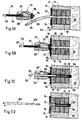
- Figures 7A-E are different views of a Darning head 120 shown.
- Figures 7A and 7B show the Top view from above or from the side.
- characters 7C, 7D and 7E show sections along the lines J-K (Fig. 7C), G-H (Fig. 7D) and A-B (Fig. 7E).
- the stuffing head 120 is on two rails 123, 124 to one Tap opening of a melting furnace, not shown here can be moved up so that its front plate 121 is form-fitting closes with the wall of the furnace.
- the housing of the Darning head 120 has a continuous longitudinal bore 128, 129 for pushing a lance in and out.
- On Supply channel 127 for stuffing material opens into the furnace Area of the longitudinal bore 128 into the through bore 129 the front plate 121.
- Cooling channels 125, 125 ' arranged to cool the Stuffing head 120, in particular its the melt stream exposed front plate 121, to a cooling circuit can be connected (connection 126).
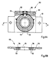
- FIGS. 8A and 8B show the front plate 130 of a melting furnace in a partially sectioned view from the front (Fig. 8A) or in cross section along the line C-D.
- the front plate 130 has a round central bore 131 on, concentric with the tap hole of a furnace is arranged. A runs around the center bore 131 Cooling channel 133, which via connections 134, 135 to one Cooling circuit can be connected.
- the cooling channel 133 is by notches in the flat body 132 of the Front plate 130 formed with an annular Disc 136 are covered.
Landscapes
- Engineering & Computer Science (AREA)
- Chemical & Material Sciences (AREA)
- Mechanical Engineering (AREA)
- Materials Engineering (AREA)
- Metallurgy (AREA)
- Organic Chemistry (AREA)
- Manufacturing & Machinery (AREA)
- General Engineering & Computer Science (AREA)
- Furnace Charging Or Discharging (AREA)
- Gasification And Melting Of Waste (AREA)
- Processing Of Solid Wastes (AREA)
- Carbon Steel Or Casting Steel Manufacturing (AREA)
- Vertical, Hearth, Or Arc Furnaces (AREA)
Abstract
Description
Die Erfindung betrifft eine Abstichvorrichtung für einen
Schmelzofen gemäss dem Oberbegriff von Anspruch 1 sowie
eine Lanze zum Verschliessen und Öffnen der Abstichöffnung
eines Schmelzofens. Ferner betrifft die Erfindung ein
Abstichverfahren für einen Schmelzofen gemäss dem
Oberbegriff von Anspruch 14.The invention relates to a tapping device for a
Melting furnace according to the preamble of claim 1 and
a lance to close and open the tap hole
a melting furnace. The invention further relates to a
Tapping process for a melting furnace according to the
Preamble of
Aus der GB 2 285 675 ist eine gattungsgemässe Abstichvorrichtung mit einer Fülleinrichtung zum Füllen der offenen Abstichöffnung mit einer Stopfmasse und mit einer verfahrbaren Stopfeinrichtung zum Einführen einer Lanze in die Abstichöffnung bekannt. Die Lanze, ein einfacher länglicher Stab, wird dabei unter Stoss- und Rüttelbewegungen in die Abstichöffnung eingeführt, nachdem die Stopfmasse eingefüllt wurde, z.B. mit Hilfe eines Bohrhammers, und verbleibt dort bis zum erneuten Öffnen der Abstichöffnung durch Herausziehen der Lanze.GB 2 285 675 is a generic tapping device with a filling device for filling the open tap hole with a stuffing and one movable tamping device for inserting a lance into the tap opening is known. The lance, a simple one elongated rod, is under impact and Vibrations introduced into the tap hole after the stuffing has been filled in, e.g. with help of a Hammer, and remains there until reopened the tap opening by pulling out the lance.
Aus der DE 3 803 132 A1 ist eine Abstichvorrichtung bekannt, bei der zum Schliessen der Abstichöffnung eine Stopfmasse eingepresst und gleichzeitig eine bis zum Abstich des Ofens im Stichloch verbleibende Lanze in die Stopfmasse eingebracht wird. Dazu weist die Abstichvorrichtung einen Stopfkopf mit einer Durchgangsbohrung auf, durch welche sowohl die Stopfmasse als auch die Lanze in die Abstichöffnung eingeführt wird.DE 3 803 132 A1 describes a tapping device known in which a to close the tap hole Pressed in stuffing and at the same time one to Tapping the furnace into the lance remaining in the tap hole Stuffing is introduced. For this purpose, the tapping device a stuffing head with a through hole through which both the stuffing and the lance is inserted into the tap hole.
Problematisch hieran sind die hohen Temperaturen im Inneren des Schmelzofens, die zu Beschädigungen des Materials der Abstichöffnung und der darin enthaltenen ausgehärteten Stopfmasse führen können. Des Weiteren werden beim Einführen der Lanze in die angehärtete Stopfmasse hohe Kräfte auf die Ofenwandung im Bereich der Abstichöffnung ausgeübt. Zum Ausschluss von Ofendurchbrüchen ist daher im Bereich der Abstichöffnung eine Mindestwandstärke notwendig, die in der Regel über der Wandstärke in den übrigen Bereichen des Schmelzofens liegt. Diese Wandstärke liegt üblicherweise im Bereich von etwa 600-800 mm. Sie bedingt eine Mindestgrösse des Schmelzofens und einen Mindestplatzbedarf, der insbesondere bei Müllverbrennungsanlagen oft über den verfügbaren Platz hinausgeht.The high temperatures in the Inside the melting furnace, causing damage to the Material of the tap opening and the contained therein can cause hardened stuffing. Furthermore are when the lance is inserted into the hardened Darning mass high forces on the furnace wall in the area of Tapping hole exercised. To exclude furnace breakthroughs is therefore in the area of the tap opening Minimum wall thickness necessary, which is usually above the Wall thickness in the remaining areas of the melting furnace lies. This wall thickness is usually in the range of about 600-800 mm. It requires a minimum size of the Melting furnace and a minimum space requirement, in particular in waste incineration plants often over the available space.
Es ist Aufgabe der Erfindung, eine Abstichvorrichtung bzw. ein Abstichverfahren anzugeben, mit der bzw. durch das die Abstichöffnung wiederholt schnell und sicher verschlossen und geöffnet werden kann und die eine reduzierte Wandstärke des Schmelzofens erlaubt. Dazu sollen bekannte Lanzen weiterentwickelt werden.It is an object of the invention to provide a tapping device or to specify a tapping procedure by means of which The tap opening is closed quickly and safely and can be opened and the reduced one Wall thickness of the melting furnace allowed. Well known Lances to be developed further.
Die Aufgabe wird gelöst durch eine Abstichvorrichtung mit
den Merkmalen von Anspruch 1, durch ein Abstichverfahren
mit den Merkmalen von Anspruch 13 und durch eine kühlbare
Lanze mit den Merkmalen von Anspruch 10.The task is solved with a tapping device
the features of claim 1, by a tapping process
with the features of claim 13 and by a coolable
Lance with the features of
Die offene Abstichöffnung wird zunächst mit Hilfe der Fülleinrichtung mit der Stopfmasse gefüllt. Sobald die Stopfmasse hineingedrückt wurde, spätestens aber nach einigen Sekunden, führt die Stopfeinrichtung die Lanze in die Abstichöffnung ein. Alternativ kann die Lanze gleichzeitig mit der Stopfmasse eingeführt werden. In beiden Fällen wird ein Teil der in der Abstichöffnung befindlichen Stopfmasse von der Lanze weiter in die Abstichöffnung gedrückt. Durch die im Schmelzofen wirkende Hitze härtet die Stopfmasse aus. Die in die Abstichöffnung eingeführte Lanze wird von aussen mechanisch gesichert. Zum Öffnen der Abstichöffnung wird die Lanze gezogen. Dabei wird durch den von der im Schmelzofen befindlichen Schmelze verursachten hydrostatischen Druck die noch in der Abstichöffnung befindliche Stopfmasse aus der Abstichöffnung gedrückt, so dass die Schmelze ungehindert aus dem Schmelzofen durch die Abstichöffnung abfliessen kann. Zum erneuten Verschliessen wird die Abstichöffnung von der Fülleinrichtung wieder mit Stopfmasse gefüllt und die Lanze mit Hilfe der Stopfeinrichtung in die Abstichöffnung eingeführt. Durch Verwendung einer gekühlten Lanze wird das Material in der Umgebung der Abstichöffnung ebenfalls gekühlt. Die Gefahr von Hitzeschäden sinkt, und die Lebensdauer und Betriebssicherheit des Schmelzofens wird erhöht. Die Kühlung verhindert zudem, dass die Lanze an ihrem vorderen Ende schmilzt, das der grössten Hitzebelastung ausgesetzt ist. Die Kühlung erlaubt somit die Konstruktion von Schmelzöfen mit geringerer Wanddicke.The open tap hole is first opened using the Filling device filled with the stuffing. As soon as the Stuffing was pressed in, but at the latest after a few seconds, the tamping device guides the lance in the tap hole. Alternatively, the lance be introduced simultaneously with the stuffing. In Both cases will be part of the tap opening from the lance into the Tap hole pressed. By acting in the furnace Heat hardens the stuffing. The in the tap hole The inserted lance is mechanically secured from the outside. The lance is pulled to open the tap hole. This is done by the one in the furnace Melt caused hydrostatic pressure to still build in the tamping material from the tap opening pressed so that the melt unhindered from the Can flow through the tap opening. To the The tap hole is closed again by the Filling device again filled with stuffing and the Use the tamping device to lance into the tap hole introduced. By using a chilled lance the material in the vicinity of the tap opening also chilled. The risk of heat damage decreases, and that Lifespan and operational safety of the melting furnace elevated. The cooling also prevents the lance from turning on its front end melts, that of the largest Is exposed to heat. The cooling thus allows the construction of melting furnaces with a smaller wall thickness.
Die Wanddicke kann von herkömmlich 600-800 mm auf etwa die Hälfte bis ein Drittel reduziert werden. Somit sind kleinere und damit auch billigere Schmelzöfen konstruierbar, die insbesondere zum Aufschmelzen der Verbrennungsrückstände bei Müllverbrennungsanlagen geeignet sind.The wall thickness can be from the conventional 600-800 mm to approximately that Half to a third can be reduced. So are smaller and therefore cheaper melting furnaces constructible, in particular for melting the Combustion residues in waste incineration plants are suitable.
Vorteilhafte Weiterbildungen der Erfindung ergeben sich aus der nachfolgenden Beschreibung, der Zeichnung sowie den anhängigen Ansprüchen.Advantageous further developments of the invention result from the following description, the drawing and the pending claims.
Insbesondere ist die Lanze vorzugsweise aus Kupfer oder einer Kupferlegierung gefertigt und mit mindestens einem Kühlkanal versehen, der an eine Kühlwasserversorgung angeschlossen werden kann. In particular, the lance is preferably made of copper or made of a copper alloy and with at least one Cooling channel provided that connects to a cooling water supply can be connected.
Vorzugsweise sind bei einer Abstichvorrichtung auch der Stopfkopf und/oder der Bereich um die Abstichöffnung gekühlt. Dadurch wird der Kühleffekt weiter verbessert.Preferably, in a tapping device Darning head and / or the area around the tap hole chilled. This further improves the cooling effect.
Bei einer weiteren bevorzugten Ausführungsform ist vor der Abstichöffnung des Schmelzofens eine vorzugsweise aus Kupfer oder einem ähnlichen wärmeleitfähigen Material gefertigte Frontplatte mit einer Austrittsöffnung angeordnet, die die Abstichöffnung freilässt. Der Stopfkopf der Stopfeinrichtung ist beim Einführen der Lanze in die Abstichöffnung vorzugsweise formschlüssig an die Platte ansetzbar, die als Dichtungselement zwischen der Stopfeinrichtung und der Abstichöffnung wirkt. Zur Erhöhung des Kühleffektes der Lanze und zur Vermeidung einer Beschädigung der Platte durch übermässige Hitzeeinwirkung ist in einer besonders bevorzugten Weiterbildung der Erfindung auch diese Platte kühlbar, z.B. mittels Wasserkühlung.In a further preferred embodiment is before Tapping opening of the melting furnace one preferably Copper or similar thermally conductive material manufactured front panel with an outlet opening arranged, which leaves the tap opening. The The stuffing head of the stuffing device is when inserting the Lance into the tap hole preferably with a positive fit the plate can be used as a sealing element between the tamping device and the tap opening. For Increasing the cooling effect of the lance and avoiding it damage to the plate due to excessive Exposure to heat is particularly preferred Further development of the invention, this plate can also be cooled, e.g. by means of water cooling.
In einer weiteren bevorzugten Weiterbildung der Erfindung ist auch der Stopfkopf gekühlt, wodurch der Kühleffekt verstärkt und die Wärmeabfuhr der Lanze verbessert wird.In a further preferred development of the invention the stuffing head is also cooled, which creates the cooling effect reinforced and the heat dissipation of the lance is improved.
Bei einer weiteren bevorzugten Ausführungsform weist der Stopfkopf zusätzlich einen Versorgungskanal auf, der in die Durchgangsbohrung des Stopfkopfes mündet. Der Versorgungskanal ist mit der Fülleinrichtung verbunden, die die zum Schliessen der Abstichöffnung erforderliche Stopfmasse durch den Versorgungskanal und die Durchgangsbohrung in die Abstichöffnung fördert. Die anschliessend durch die Durchgangsbohrung eingeführte Lanze schiebt die noch in der Durchgangsbohrung und in der Abstichöffnung enthaltene Stopfmasse in ihre endgültige Lage in der Abstichöffnung, wodurch eine gleichmässige Verteilung der Stopfmasse um die Lanze in der Abstichöffnung gewährleistet ist. Gleichzeitig wird durch die Integration der Füllfunktion in den Stopfkopf ein sehr schnelles, sicheres und schonendes Schliessen der Abstichöffnung ermöglicht, da das Beiseitefahren der sonst separat ausgebildeten Fülleinrichtung und das nachfolgende Ansetzen der Stopfeinrichtung sowie eine erhöhte Krafteinwirkung beim Eintreiben der Lanze entfallen kann.In a further preferred embodiment, the Darning head additionally on a supply channel, which in the through hole of the stuffing head opens. The Supply channel is connected to the filling device, which is required to close the tap hole Stuffing mass through the supply channel and Through hole in the tap hole promotes. The then inserted through the through hole Lance pushes them in the through hole and in the Tap hole contained in its final filling Position in the tap hole, creating an even Distribution of the stuffing mass around the lance in the Tap opening is guaranteed. At the same time, through the integration of the filling function in the stuffing head a very fast, safe and gentle closing of the Tap-off opening is possible because moving aside the otherwise separately designed filling device and the subsequent one Attach the darning device as well as an increased The action of force when driving in the lance can be dispensed with.
Vorteilhaft ist weiterhin, wenn vor dem Füllen der Abstichöffnung mit Stopfmasse ein Holzstopfen in die Abstichöffnung eingebracht wird. Dieser ist beispielsweise in der Durchgangsbohrung des Stopfkopfes angeordnet ist und wird durch den Druck der Stopfmasse, gegebenenfalls unterstützt durch den Druck der Lanze, in die Abstichöffnung befördert, durch diese hindurchgeschoben, in die Schmelze gestossen und verbrannt. Auf diese Weise wird verhindert, dass durch die Kühlung der Lanze und des Stopfkopfes oder der Frontplatte die Schmelze örtlich so weit abgekühlt wird, dass sich Metallplatten in der Abstichöffnung bilden.It is also advantageous if before filling the Tap hole with stuffing into the wooden plug Tapping opening is introduced. This is for example is arranged in the through hole of the stuffing head and is determined by the pressure of the stuffing, if necessary supported by the pressure of the lance into the Tapped opening pushed through it, thrown into the melt and burned. In this way is prevented by cooling the lance and the The melt or the front plate locally is cooled far enough that metal plates in the Form the tap hole.
In einer weiteren vorteilhaften Weiterbildung der Erfindung weist die Lanze eine Hülse auf, die an ihrem der Abstichöffnung zugewandten Ende aufgesetzt ist. Die Hülse besteht aus einem Material, das den gleichen oder einen geringeren Schmelzpunkt hat wie die im Schmelzofen enthaltenen Schmelze, vorzugsweise aus Kupfer oder einer Kupferlegierung. Beim Ziehen der Lanze verbleibt die Hülse in der Abstichöffnung und wird durch die Schmelze abgeschmolzen, so dass der Schmelzenstrahl ausfliessen kann. Die Hülse hat den Vorteil, dass das Ziehen der Lanze vereinfacht wird, da ihre Kontaktfläche mit der Stopfmasse verringert wird. Die Lanze wird demnach weniger beschädigt und kann wiederverwendet werden. Die Hülse ist ein Verschleissteil.In a further advantageous development of the Invention, the lance has a sleeve on which the Tapping hole facing end is placed. The sleeve consists of a material that is the same or one has a lower melting point than that in the melting furnace contained melt, preferably made of copper or a Copper alloy. The sleeve remains when the lance is pulled in the tap hole and is through the melt melted off so that the melt jet flow out can. The sleeve has the advantage of pulling the lance is simplified because its contact surface with the stuffing is reduced. The lance is therefore less damaged and can be reused. The sleeve is a Wear part.
Zum Einführen der Lanze durch die Durchgangsbohrung des Stopfkopfes dient eine Vorschubeinheit. Durch die Verwendung des Stopfkopfes wird die Abstichöffnung während des Einführens der Lanze nach aussen zumindest teilweise abgedichtet. Gleichzeitig gewährleistet die im Stopfkopf ausgebildete Durchgangsbohrung, dass die Lanze in einer definierten Einführrichtung in die Abstichöffnung eingeführt wird, so dass eventuelle Beschädigungen des feuerfesten Materials im Bereich der Abstichöffnung vermieden werden.To insert the lance through the through hole of the A feed unit is used for the stuffing head. Through the Using the stuffing head will open the tap hole during the insertion of the lance to the outside at least partially sealed. At the same time ensures that in the stuffing head trained through hole that the lance in a defined direction of insertion into the tap hole is introduced so that any damage to the refractory material in the tap hole area be avoided.
Als Vorschubeinheit für die Stopfeinrichtung eignet sich insbesondere ein Bohrhammerwerk oder ein hydraulischer Antrieb. Durch ein Bohrhammerwerk kann neben der Vorschubbewegung der Lanze gleichzeitig eine rotatorische Bewegung der Lanze um ihre Längsachse sowie eine Rüttelbewegung in Richtung ihrer Längsachse erzeugt werden. Durch die kombinierte Rotations- und Rüttelbewegung verteilt sich die in der Abstichöffnung enthaltene Stopfmasse besonders gleichmässig um die sich in die Abstichöffnung bewegende Lanze, während gleichzeitig der Vorschubbewegung der Lanze entgegen wirkende Kräfte geringer sind als bei einer Lanze, die ausschliesslich mit einer Axialbewegung in die Abstichöffnung eingeführt wird. Jedoch kann auf die Rotation auch verzichtet werden.A suitable feed unit for the tamping device especially a rotary hammer mill or a hydraulic one Drive. A hammer mill can be used in addition to the Feed movement of the lance simultaneously a rotary Movement of the lance about its longitudinal axis and one Vibrating movement generated in the direction of its longitudinal axis become. Due to the combined rotation and The shaking movement is distributed in the tap opening contained stuffing particularly evenly around the lance moving into the tap hole while at the same time against the advancing movement of the lance acting forces are less than with a lance, the exclusively with an axial movement in the Tapping hole is introduced. However, on the Rotation can also be dispensed with.
An der Abstichvorrichtung kann zusätzlich eine Auszieheinrichtung vorgesehen sein, die zum Herausziehen der in die Abstichöffnung eingeführten, diese verschliessenden Lanze dient. Durch diese zusätzliche Funktionseinheit an der Abstichvorrichtung wird ein vollautomatisches Öffnen und Schliessen der Abstichöffnung ermöglicht, so dass die Abstichöffnung und die Giessrinne des Schmelzofens gemeinsam mit den Funktionseinheiten der Abstichvorrichtung in einem nach aussen abgeschlossenen Gehäuse untergebracht sein können, in dem die aus der Schmelze aufsteigenden Gase und Schwebstoffe aufgefangen und einer Reinigungs- und Filteranlage zugeführt werden können. Dies ist insbesondere bei Verwendung der Abstichvorrichtung für einen Schmelzofen einer Mühlverbrennungsanlage von Vorteil, bei der die entstehenden Gase und aufsteigenden Schwebstoffe aus Umweltschutzgründen möglichst vollständig aufgefangen und neutralisiert bzw. ausgefiltert werden müssen. Als Auszieheinrichtung eignet sich beispielsweise eine in Längsrichtung der Abstichöffnung verfahrbare Halterung, die an die Lanze ankoppelbar ist.An extracting device can also be attached to the tapping device be provided for pulling out the in inserted the tap hole, closing it Lance serves. Through this additional functional unit the tapping device is a fully automatic opening and closing the tap opening so that the Tap hole and the trough of the melting furnace together with the functional units of the tapping device in a housing closed to the outside Can be accommodated in which the melt rising gases and suspended matter and one Cleaning and filter system can be supplied. This is especially useful when using the tapping device a melting furnace of a mill incinerator from Advantage in which the emerging gases and ascending Suspended matter as completely as possible for environmental reasons caught and neutralized or filtered out have to. A suitable pull-out device is, for example a movable in the longitudinal direction of the tap opening Bracket that can be coupled to the lance.
Nachfolgend wird die Erfindung anhand von Ausführungsbeispielen unter Bezugnahme auf die Zeichnung näher erläutert. Darin zeigen:
- Fig. 1
- eine teilweise geschnittene Seitenansicht einer erfindungsgemässen Abstichvorrichtung bei geschlossener Abstichöffnung eines Schmelzofens,
- Fig. 2
- eine teilweise geschnittene Seitenansicht der Abstichvorrichtung nach Fig. 1 unmittelbar nach dem Öffnen der Abstichöffnung,
- Fig. 3
- eine teilweise geschnittene Seitenansicht der Abstichvorrichtung nach Fig. 1 beim Befüllen der Abstichöffnung mit einer Stopfmasse, und
- Fig. 4
- eine teilweise geschnittene Seitenansicht der Abstichvorrichtung nach Fig. 1 nach dem Einführen einer die Abstichöffnung verschliessenden Lanze;
- Fig. 5A-D
- eine geschnittene Seitenansicht eines Stopfkopfes mit Stopfmasse und Lanze sowie eines Schmelzofens zur Darstellung verschiedener Stadien des erfindungsgemässen Verfahrens;
- Fig. 6
- eine teilweise geschnittene Seitenansicht einer Lanze;
- Fig. 7A-E
- verschiedene Ansichten eines Stopfkopfes mit Kühlung;
- Fig. 8A,B
- verschiedene Ansichten einer Frontplatte mit Kühlung.
- Fig. 1
- 2 shows a partially sectioned side view of a tapping device according to the invention with the tap opening of a melting furnace closed,
- Fig. 2
- 2 shows a partially sectioned side view of the tapping device according to FIG. 1 immediately after opening the tapping opening,
- Fig. 3
- a partially sectioned side view of the tapping device of FIG. 1 when filling the tap opening with a stuffing, and
- Fig. 4
- a partially sectioned side view of the tapping apparatus of Figure 1 after inserting a lance closing the tap opening.
- 5A-D
- a sectional side view of a stuffing head with stuffing and lance and a melting furnace to illustrate different stages of the inventive method;
- Fig. 6
- a partially sectioned side view of a lance;
- 7A-E
- different views of a stuffing head with cooling;
- 8A, B
- different views of a front panel with cooling.
Die Fig. 1 bis 4 zeigen teilweise geschnittene
Seitenansichten einer Abstichvorrichtung 10 in unterschiedlichen
Betriebspositionen beim Öffnen und Schliessen
einer Abstichöffnung 12 eines Ofens 14 einer Müllverbrennungsanlage.
Bei entsprechender Dimensionierung
kann die Abstichvorrichtung 10 auch in Giessereien und
Stahlwerken zum Öffnen und Schliessen von ähnlich
gestalteten Abstichöffnungen an Hochöfen eingesetzt
werden.1 to 4 show partially cut
Side views of a
Die Abstichvorrichtung 10 weist zwei sich etwa parallel
zur Längsrichtung der Abstichöffnung 12 erstreckende, im
Querschnitt U-förmige Träger 16 auf, die mit Abstand
zueinander verlaufen und von denen in den Fig. 1 bis 4 aus
Gründen der Übersichtlichkeit nur der im Hintergrund
angeordnete Träger 16 dargestellt ist. Die Träger 16 sind
an einem an dem Ofen 14 vorgesehenen Fülltrichter 18
befestigt, der unter der Abstichöffnung 12 angeordnet ist
und durch den die aus der Abstichöffnung 12 austretende
Schmelze beispielsweise in eine Kokille 20 (vgl. Fig. 2)
gelenkt werden kann. Mit ihren dem Fülltrichter 18
abgewandten Endabschnitten liegen die beiden Träger 16 auf
einem quer zu diesen verlaufenden ersten I-Träger 22 auf,
an dem sie befestigt sind. In Richtung des Fülltrichters
18 versetzt ist ein zweiter I-Träger 24 angeordnet, der
zwischen den beiden Trägern 16 quer zu diesen verläuft und
mit diesen fest verbunden ist. Des weiteren ist an jedem
Träger 16 ein Längsträger 26 befestigt, der im Querschnitt
L-förmig ist. Auch hier ist aus Gründen der
Übersichtlichkeit in den Fig. 1 bis 4 nur der im
Hintergrund angeordnete Längsträger 26 zu sehen. Die
Längsträger 26 sind so an den Trägern 16 befestigt, dass
ihre horizontal verlaufenden Schenkel einander zugewandt
sind und mit den oben angeordneten, gleichfalls horizontal
verlaufenden Schenkeln der U-förmigen Träger 16, die
voneinander abgewandt sind, eine im Querschnitt U-förmige
Führung bilden.The tapping
In der Führung ist ein Wagen 28 geführt, der sich durch
zwei Rollenpaare 30 und 32 auf der Oberseite der
horizontal verlaufenden Schenkel der beiden Träger 16
abrollt. Nahe dem in den Fig. 1 bis 4 rechts dargestellten
Rollenpaar 32 ist ein Anschlusselement 34 vorgesehen, das
mit dem Kolben eines Hydraulikzylinders 36 fest verbunden
ist. Der Hydraulikzylinder 36 ist mit seinem in den Fig. 1
bis 4 links dargestellten Ende an einer Schwenkaufnahme 38
schwenkbar gelagert, die mittig zwischen den Trägern 16 am
zweiten I-Träger 24 befestigt ist.In the guide, a
An seinem in den Fig. 1 bis 4 links dargestellten Ende ist
am Wagen 28 ein Stopfkopf 40 befestigt, in dem mehrere
Kühlkanäle (nicht dargestellt) ausgebildet sind, die an
eine Kühlwasserversorgung angeschlossen sind. In dem
Stopfkopf 40 ist eine in Längsrichtung des Wagens 28
verlaufende Durchgangsbohrung 42 ausgebildet, in die ein
unter einem Winkel zur Durchgangsbohrung 42 verlaufender
Versorgungskanal 44 mündet. In den Versorgungskanal 44 ist
das freie Ende eines Förderzylinders 46 eingesetzt, in dem
ein Kolben 48 verschieblich gelagert und mit Hilfe eines
hydraulischen Zylinders 50 bewegbar ist. Der Stopfkopf 40
ist entlang der Durchgangsbohrung 42 geteilt, wird mit
Hilfe zweier Verriegelungen (nicht dargestellt)
zusammengehalten und kann zu einem später noch zu
erläuternden Zweck geöffnet werden.At its end shown in Figs. 1 to 4 on the left
attached to the carriage 28 a stuffing
In der Mitte des Wagens 28 ist ein Trägerelement 52
vorgesehen, an dem das hintere Rollenpaar 32 drehbar
gelagert ist. Das Trägerelement 52 hat ein Gleitlager 54,
dessen Symmetrieachse mit der Symmetrieachse der
Durchgangsbohrung 42 des Stopfkopfes 40 zusammenfällt. In
dem Gleitlager 54 ist ein Gestänge 56 eines
Bohrhammerwerkes 58 einer Vorschubeinheit 60 drehbar und
verschieblich gelagert. Das Bohrhammerwerk 58 der
Vorschubeinheit 60 ist an einem Schieber 62 befestigt, der
mit Hilfe zweier seitlich des Bohrhammerwerkes 58
angeordneter, pneumatischer Vorschubzylinder 64 in Längsrichtung
des Wagens 28 zwischen einer Ausgangsstellung
nahe dem in den Fig. 1 bis 4 rechts dargestellten Ende des
Wagens 28, und einer Endstellung bewegbar ist, in der der
Schieber 62 nahe dem Gleitlager 54 angeordnet ist. Auch
hier ist aus Gründen der Übersichtlichkeit nur der im
Hintergrund dargestellte Vorschubzylinder 64 gezeigt.In the middle of the
Am freien Ende des Gestänge 56, in den Fig. 1 bis 4 links
dargestellt, ist ein Kupplungskopf 66 befestigt. Mit dem
Kupplungskopf 66 ist ein Kupplungsende 68 einer ersten
Lanze 70 gekoppelt, deren anderes Ende teilweise in die
Durchgangsbohrung 42 des Stopfkopfes 40 ragt. Die erste
Lanze 70 verfügt über einen Kühlkanal, der durch
Anschlüsse 72 nahe dem Kupplungsende 68 an eine
Kühlwasserversorgung angeschlossen werden kann. Ferner ist
am Wagen 28 ein sich in dessen Längsrichtung erstreckender
Kopplungshaken 74 schwenkbar gelagert, dessen Zweck später
noch erläutert wird.At the free end of the
Als weitere Funktionseinheit weist die Abstichvorrichtung
10 nahe dem Fülltrichter 18 eine Auszieheinrichtung 76
auf. Die Auszieheinrichtung 76 umfasst ein am Träger 16
befestigtes Gestell 78 mit einer in etwa parallel zur
Bewegungsrichtung des Wagens 28 entlang den Trägern 16
verlaufenden Führungsleiste 80. An der Führungsleiste 80
ist eine Halterung 82 verschieblich gehalten, die um die
Führungsleiste 80 zwischen einer Halteposition, in der die
Halterung 82 zur Abstichöffnung 12 ausgerichtet ist, und
einer Freigabeposition geschwenkt werden, in der die
Halterung 82 nach hinten vom Träger 16 weggeschwenkt ist.
Im in Fig. 1 gezeigten Betriebszustand, in der die
Halterung 82 in ihre Halteposition geschwenkt ist, ist an
die Halterung 82 eine zur ersten Lanze 70 identisch
ausgebildete zweite Lanze 84 gekoppelt, die in die
Abstichöffnung 12 des Ofens 14 eingeführt ist und die
Abstichöffnung 12 verschliesst. Dabei ist die zweite Lanze
84 an die Kühlwasserversorgung (nicht dargestellt)
angeschlossen. An der Halterung 82 ist ferner ein parallel
zur Führungsleiste 80 abstehender Mitnehmerhaken 86
vorgesehen, der zum Kopplungshaken 74 des Wagens 28
ausgerichtet ist, wenn die Halterung 82 in ihre in Fig. 1
dargestellte Halteposition geschwenkt ist. The tapping device has a further
Unter der Auszieheinrichtung 76 ist ferner eine
abgewinkelte Strahlumlenkplatte 88 angeordnet, die durch
zwei Rollenpaare (nicht dargestellt) an den Trägern 16
verschieblich gelagert und mit Hilfe eines Aktuators
(nicht dargestellt) entlang der Träger 16 bewegt werden
kann. Die Strahlumlenkplatte 88 weist an ihrem nahe der
Abstichöffnung 12 angeordneten etwa vertikal verlaufenden
Ende eine Öffnung 90 auf, deren Durchmesser so bemessen
ist, dass der Stopfkopf 40 mit seinem kegelstumpfförmig
gestalteten Anlagebereich durch die Öffnung 90
hindurchragen kann.There is also a pull-out
Um die Abstichöffnung 12 ist ferner an dem äusseren der
Lochsteine 92 der Abstichöffnung 12 eine runde Platte 94
befestigt, die mit einer kegelförmig erweiterten
Austrittsöffnung 96 versehen ist, welche konzentrisch zur
Abstichöffnung 12 des Ofens 14 angeordnet ist. Wie die
beiden Lanzen 70 und 84 ist auch die Platte 94 mit
Kühlungskanälen (nicht dargestellt) versehen, die an die
Kühlwasserversorgung angeschlossen sind.Around the
Der Stopfkopf 40 kann auch um 180° um die Horizontale
gedreht sein, wobei alle Maschinenteile oberhalb des
Stopfkopfes angeordnet sind und die Stopfmasse von oben
zugeführt wird, wie in Fig. 5A-D gezeigt. Dies hat den
Vorteil, dass der austretende Schmelzenstrahl keine Teile
der Stopfvorrichtung beschädigen und auf die Strahlumlenkplatte
verzichtet werden kann.The stuffing
Nachfolgend wird die Funktionsweise der Abstichvorrichtung
10 näher erläutert. Bei dem in Fig. 1 dargestellten
Betriebszustand befindet sich der Wagen 28 in seiner
Ausgangsposition, in der der Kolben des Hydraulikzylinders
36 eingefahren ist, während das hintere Rollenpaar 32 nahe
der Schwenkaufnahme 38 angeordnet ist. Gleichzeitig
verschliesst die in die Abstichöffnung 12 eingeführte
Lanze 84 die Abstichöffnung 12 und verhindert das
Austreten von Schmelze aus dem Ofen 14. Dabei dient die
mit der zweiten Lanze 84 verkoppelte Auszieheinrichtung 76
als Fixierung für die Lanze 84.Below is the operation of the
Vor Öffnen der Abstichöffnung 12 wird die Abstichvorrichtung
10 für das Schliessen der Abstichöffnung 12
vorbereitet. Zu diesem Zweck wird zunächst der Fülltrichter
18 mit einer schnell aushärtenden Stopfmasse
gefüllt. Ferner wird die Halterung 82 mit der daran
befestigten zweiten Lanze 84 aus der Öffnung 90 der
Strahlumlenkplatte 88 nach oben aus dem Bewegungsbereich
des Wagens 28 weg in ihre Freigabeposition geschwenkt,
wobei der Mitnehmerhaken 86 ausser Eingriff mit dem
Kopplungshaken 74 gerät. Des weiteren wird die Kühlwasserversorgung
an die an der Vorschubeinheit 60 angekoppelten
ersten Lanze 70 angeschlossen und die erste Lanze 70
gekühlt.The tapping device is opened before the tap opening 12
10 for closing the tap opening 12
prepared. For this purpose, the hopper is first
18 with a quick hardening stuffing compound
filled. Furthermore, the
Soll nun die Abstichöffnung 12 des Ofens 14 geöffnet
werden, wird zunächst mit Hilfe des Hydraulikzylinders 36
der Wagen 28 in Richtung der Abstichöffnung 12 so weit
bewegt, bis der Kopplungshaken 74 mit dem Mitnehmerhaken
86 der Ausziehvorrichtung 76 in Eingriff kommt.
Anschliessend wird der Wagen 28 durch den Hydraulikzylinder
36 wieder in seine Ausgangsstellung zurückbewegt,
wobei der mit dem Mitnehmerhaken 86 in Eingriff stehende
Kopplungshaken 74 die Halterung 82 entlang der
Führungsleiste 80 mitzieht. Dadurch wird die an die
Halterung 82 angekoppelte zweite Lanze 84 aus der
Abstichöffnung 12 gezogen, wie in Fig. 2 dargestellt.
Gleichzeitig mit der Bewegung des Wagens 28 bewegt der
Aktuator die Strahlumlenkplatte 88 von der Abstichöffnung
12 weg und gibt den Fülltrichter 18 frei. Unter dem
Fülltrichter 18 wurde zwischenzeitlich die Kokille 20
positioniert, in die die aus der Abstichöffnung 12
austretende Schmelze fliesst.Now the tap opening 12 of the
Soll nun die Abstichöffnung 12 verschlossen werden, wird
der Wagen 28 gemeinsam mit der Strahlumlenkplatte 88 auf
die Abstichöffnung 12 zu bewegt. Dabei ragt der
kegelstumpfförmige Kopfabschnitt des Stopfkopfes 40 durch
die Öffnung 90 der Strahlumlenkplatte 88. Der
Hydraulikzylinder 36 wird soweit ausgefahren, bis der
Stopfkopf 40 mit seinem kegelstumpfförmigen Kopfabschnitt
zumindest teilweise in der kegelförmigen Austrittsöftnung
96 der Platte 94 aufgenommen ist, wie in Fig. 3
dargestellt. Anschliessend wird der hydraulische Zylinder
50 des Förderzylinders 46 angeschaltet, durch den der
Kolben 48 sich in Richtung der Durchgangsbohrung 42
bewegt. Dabei wird die im Förderzylinder 46 enthaltende
Stopfmasse durch den Versorgungskanal 44 und dich
Durchgangsbohrung 42 in die Abstichöffnung 12 gedrückt,
wie in Fig. 3 gezeigt ist.If the
Sobald eine ausreichende Menge Stopfmasse in die
Abstichöffnung 12 gefüllt wurde, wird das Bohrhammerwerk
58 der Vorschubeinheit 60 angeschaltet und die
Vorschubzylinder 64 der Vorschubeinheit 60 unter Druck
gesetzt. Durch die Vorschubzylinder 64 wird das
Bohrhammerwerk 58 von dem Schieber 52 in Richtung der
Abstichöffnung 12 bewegt, wobei die erste Lanze 70
kontinuierlich unter gleichmässiger Drehung und rüttelnden
Bewegungen in die Abstichöffnung 12 eingeführt wird. Dabei
wird die in der Abstichöffnung 12 enthaltene Stopfmasse
gleichmässig an der Innenwand der Abstichöffnung 12
verteilt, so dass die erste Lanze 70 gleichmässig in die
in der Abstichöffnung 12 enthaltene Stopfmasse eingebettet
ist. In diesem in Fig. 4 dargestellten Betriebszustand
wird der Wagen 28 über einen vorgegebenen Zeitraum von
beispielsweise 15 Minuten gehalten, bis die schnell
härtende Stopfmasse in der Abstichöffnung 12 ausgehärtet
ist. Sobald die Stopfmasse ausgehärtet ist, wird der
Kupplungskopf 66 am Gestänge 56 des Bohrhammerwerkes 58
von der ersten Lanze 70 gelöst, die Verriegelungen am
Stopfkopf 40 entriegelt und der geteilt ausgebildete
Stopfkopf 40 geöffnet. Der Wagen wird durch einen
Senkzylinder 97 gesenkt. Anschliessend wird der Wagen 28
wieder in seine Ausgangsposition zurückbewegt.As soon as a sufficient amount of stuffing is poured into the
Während dessen wurde die zweite Lanze 84 von der Halterung
82 der Auszieheinrichtung 76 gelöst und die Halterung 82
an das Kupplungsende 86 der ersten Lanze 70 angekuppelt.
Die zweite Lanze 84 kann, sofern sie noch wiederverwendbar
ist, in den zwischenzeitlich gereinigten Stopfkopf 40
eingelegt und mit dem Kupplungskopf 66 des Bohrhammerwerkes
58 verkuppelt werden. Nachdem die zweite Lanze 84
eingesetzt und der Stopfkopf 40 wieder verriegelt worden
ist, wird der Wagen 28 wieder in seine Ausgangsstellung
zurückgefahren, so dass sich die Abstichvorrichtung 10
wieder in ihrer in Fig. 1 dargestellten Ausgangsposition
befindet.During this time, the
Bei dem dargestellten Ausführungsbeispiel wurde ein
Stopfkopf 40 verwendet, an dem der Förderzylinder 86
befestigt ist. Alternativ ist es auch möglich, an den
Versorgungskanal 44 des Stopfkopfes 40 eine Versorgungsleitung
anzuschliessen, durch die beispielsweise mit Hilfe
einer volumetrisch wirksamen Pumpe dem Stopfkopf 40
Stopfmasse zugeführt werden kann.In the illustrated embodiment, a
In den Fig. 5A-D ist der Ablauf des Stopfvorgangs nach dem
erfindungsgemässen Verfahren schematisch dargestellt. Ein
Schmelzofen 108 enthält in seinem durch eine Wandung 111
und 112 begrenzten Inneren eine Schmelze 110. Die Schmelze
110 fliesst durch eine Abstichöffnung 113 in der Wandung
112 als Schmelzenstrahl 109 aus dem Schmelzofen 108. Der
Schmelzofen 108 weist im Bereich der Abstichöffnung 113
eine vorzugsweise gekühlte Frontplatte 114 auf.5A-D is the sequence of the tamping process after
The method according to the invention is shown schematically. On
Zum Verschliessen der Abstichöffnung 113 fährt ein
Stopfkopf 101 gegen den Schmelzenstrahl 109, Fig. 5A. In
einer Öffnung in einer vorzugsweise gekühlten Vorderplatte
106 des Stopfkopfes 101 ist ein Holzstopfen 115 angeordnet,
der zuerst zur Verhinderung des vorzeitigen
Erstarrens der Schmelze in die Abstichöffnung 113
eingeführt wird, Fig. 5B. Sodann wird die durch den
Stopfkopf 101 zugeführte Stopfmasse 107 in die Abstichöffnung
113 eingepresst. Eine Lanze 102 wird durch eine
durchgehende Längsbohrung im Gehäuse 105 des Stopfkopfes
101 in die Abstichöffnung 1113 nachgeführt, Fig. 5C. Die
Lanze 102 besteht aus einem länglichen vorzugsweise
gekühlten Lanzengrundkörper 103, auf dessen vorderes Ende
103' eine an ihrem dem Ofen zugewandten Ende geschlossene
Hülse 104 aufgesteckt ist. Durch die Lanze 103 wird die
Stopfmasse 107 und der Holzstopfen 115 teilweise bis in
die Schmelze 110 hineingedrückt. Der Holzstopfen 115
verbrennt dann in der Schmelze 110. Die Lanze 103
erstreckt sich im eingeschobenen Zustand über die gesamte
Länge der Abstichöffnung 113, vorzugsweise ragt die
vordere Spitze der Hülse 104 bis in die Schmelze 110. Um
den Ofen verschlossen zu halten, wird die Lanze 103
mechanisch gesichert.To close the
Beim Ofenabstich wird zunächst der dazu vorzugsweise
zweiteilig ausgebildete Stopfkopf 101 entfernt. Sodann
wird die Lanze 102 bzw. der Lanzengrundkörper 103 gezogen,
Fig. 5D. Die Hülse 104 verbleibt in der Abstichöffnung 113
und schmilzt, so dass die Schmelze 110 als Schmelzenstrahl
austreten kann.When tapping the oven, this is preferred first
two-
Figur 6 zeigt eine teilweise geschnittene Seitenansicht
einer Lanze 116 mit einem länglichen Lanzengrundkörper
137. Der Lanzengrundkörper 137 weist einen Kühlkanal 119
auf, der im wesentlichen entlang der Längsachse der Lanze
116 verläuft und sich über etwa 2/3 der Gesamtlänge der
Lanze erstreckt. Zur Realisierung eines Kühlkreislaufs
sind zwei Anschlüsse 117, 118 für die Zufuhr und Abfuhr
von Kühlwasser vorgesehen. Die Länge der Lanze beträgt
vorzugsweise 180-250 cm. Ihr Durchmesser beträgt vorzugsweise
30-50 mm.Figure 6 shows a partially sectioned side view
a
In den Figuren 7A-E sind verschiedene Ansichten eines
Stopfkopfes 120 dargestellt. Figur 7A und 7B zeigen den
Stopfkopf in Aufsicht von oben bzw. von der Seite. Figuren
7C, 7D und 7E zeigen Schnitte entlang der Linien J-K (Fig.
7C), G-H (Fig. 7D) und A-B (Fig. 7E).In Figures 7A-E are different views of a
Der Stopfkopf 120 ist auf zwei Schienen 123, 124 an eine
hier nicht gezeigte Abstichöffnung eines Schmelzofens
heranfahrbar, so dass seine Vorderplatte 121 formschlüssig
mit der Wandung des Ofens abschliesst. Das Gehäuse des
Stopfkopfes 120 weist eine durchgehende Längsbohrung 128,
129 zum Ein- und Durchschieben einer Lanze auf. Ein
Versorgungskanal 127 für Stopfmasse mündet im ofenseitigen
Bereich der Längsbohrung 128 in die Durchgangsbohrung 129
der Vorderplatte 121. Um den Stopfkopf 120 bei eingeschobener
Lanze entfernen zu können, besteht sein Gehäuse
aus zwei Gehäuseteilen 122A, 122B, die formschlüssig
zusammengesetzt sind.The stuffing
In der Vorderplatte 121 und im Gehäuse 122A, 122B sind
Kühlkanäle 125, 125' angeordnet, die zur Kühlung des
Stopfkopfes 120, insbesondere seiner dem Schmelzenstrahl
ausgesetzten Vorderplatte 121, an einen Kühlkreislauf
anschliessbar sind (Anschluss 126).In the
Figur 8A und 8B zeigen die Frontplatte 130 eines Schmelzofens
in teilweise geschnittener Ansicht von vorne (Fig.
8A) bzw. im Querschnitt entlang der Linie C-D.FIGS. 8A and 8B show the
Die Frontplatte 130 weist eine runde Mittenbohrung 131
auf, die konzentrisch zur Abstichöffnung eines Ofens
angeordnet wird. Um die Mittenbohrung 131 verläuft ein
Kühlkanal 133, der über Anschlüsse 134, 135 an einen
Kühlkreislauf angeschlossen werden kann. Der Kühlkanal 133
ist durch Einkerbungen im flachen Grundkörper 132 der
Frontplatte 130 gebildet, die mit einer ringförmigen
Scheibe 136 abgedeckt werden.The
Claims (16)
Applications Claiming Priority (2)
| Application Number | Priority Date | Filing Date | Title |
|---|---|---|---|
| CH124599 | 1999-07-07 | ||
| CH124599 | 1999-07-07 |
Publications (2)
| Publication Number | Publication Date |
|---|---|
| EP1069191A1 true EP1069191A1 (en) | 2001-01-17 |
| EP1069191B1 EP1069191B1 (en) | 2005-09-28 |
Family
ID=4205878
Family Applications (1)
| Application Number | Title | Priority Date | Filing Date |
|---|---|---|---|
| EP20000113436 Expired - Lifetime EP1069191B1 (en) | 1999-07-07 | 2000-06-24 | Tapping apparatus and method |
Country Status (3)
| Country | Link |
|---|---|
| EP (1) | EP1069191B1 (en) |
| JP (1) | JP2001056185A (en) |
| DE (1) | DE50011237D1 (en) |
Cited By (4)
| Publication number | Priority date | Publication date | Assignee | Title |
|---|---|---|---|---|
| EP1233077A1 (en) * | 2001-02-15 | 2002-08-21 | Productos Refractarios Asturianos Para La Siderurgia, S.A. | System for repairing blast furnace taphole facings |
| US10844466B2 (en) | 2015-10-19 | 2020-11-24 | Nippon Steel Corporation | Hot forging steel and hot forged product |
| CN112857052A (en) * | 2021-02-01 | 2021-05-28 | 琪玥环保设备(唐山)有限公司 | Hole blocking device and plasma furnace with same |
| WO2022233414A1 (en) * | 2021-05-06 | 2022-11-10 | Tmt Tapping Measuring Technology Sàrl | Oxygen lance guiding assembly |
Families Citing this family (1)
| Publication number | Priority date | Publication date | Assignee | Title |
|---|---|---|---|---|
| CN105698541B (en) * | 2015-12-31 | 2018-05-18 | 遵义伟明铝业有限公司 | A kind of closing device of aluminium melting furnace discharge port |
Citations (9)
| Publication number | Priority date | Publication date | Assignee | Title |
|---|---|---|---|---|
| US2294162A (en) * | 1942-08-25 | Blast furnace cinder notch stopper | ||
| JPS52150703A (en) * | 1976-06-11 | 1977-12-14 | Nippon Steel Corp | Tap hole opening in blast furnace |
| JPS5585609A (en) * | 1978-12-21 | 1980-06-27 | Nippon Steel Corp | Boring method for tap hole of blast furnace |
| JPS5690906A (en) * | 1979-12-24 | 1981-07-23 | Kawasaki Steel Corp | Temperature controlling method of mud for closing iron notch |
| DD258721A3 (en) * | 1986-03-26 | 1988-08-03 | Funk A Bergbau Huettenkombinat | METHOD AND DEVICE FOR CLOSING A STITCH OPENING |
| DD259760A3 (en) * | 1988-06-18 | 1988-09-07 | Funk A Bergbau Huettenkombinat | DEVICE FOR CLOSING A STITCH OPENING |
| US4909487A (en) * | 1988-02-03 | 1990-03-20 | Dango & Dienenthal Maschinenbau Gmbh | Process and notch gun for closing the tapholes of furnaces |
| FR2680179A1 (en) * | 1991-08-07 | 1993-02-12 | Boulonnais Terres Refractaires | Improvements made to devices for plugging casting holes of blast furnaces |
| US5511768A (en) * | 1994-01-17 | 1996-04-30 | Paul Wurth S.A. | Tap hole plugging device |
-
2000
- 2000-06-24 EP EP20000113436 patent/EP1069191B1/en not_active Expired - Lifetime
- 2000-06-24 DE DE50011237T patent/DE50011237D1/en not_active Expired - Fee Related
- 2000-07-07 JP JP2000206591A patent/JP2001056185A/en active Pending
Patent Citations (9)
| Publication number | Priority date | Publication date | Assignee | Title |
|---|---|---|---|---|
| US2294162A (en) * | 1942-08-25 | Blast furnace cinder notch stopper | ||
| JPS52150703A (en) * | 1976-06-11 | 1977-12-14 | Nippon Steel Corp | Tap hole opening in blast furnace |
| JPS5585609A (en) * | 1978-12-21 | 1980-06-27 | Nippon Steel Corp | Boring method for tap hole of blast furnace |
| JPS5690906A (en) * | 1979-12-24 | 1981-07-23 | Kawasaki Steel Corp | Temperature controlling method of mud for closing iron notch |
| DD258721A3 (en) * | 1986-03-26 | 1988-08-03 | Funk A Bergbau Huettenkombinat | METHOD AND DEVICE FOR CLOSING A STITCH OPENING |
| US4909487A (en) * | 1988-02-03 | 1990-03-20 | Dango & Dienenthal Maschinenbau Gmbh | Process and notch gun for closing the tapholes of furnaces |
| DD259760A3 (en) * | 1988-06-18 | 1988-09-07 | Funk A Bergbau Huettenkombinat | DEVICE FOR CLOSING A STITCH OPENING |
| FR2680179A1 (en) * | 1991-08-07 | 1993-02-12 | Boulonnais Terres Refractaires | Improvements made to devices for plugging casting holes of blast furnaces |
| US5511768A (en) * | 1994-01-17 | 1996-04-30 | Paul Wurth S.A. | Tap hole plugging device |
Non-Patent Citations (3)
| Title |
|---|
| PATENT ABSTRACTS OF JAPAN vol. 002, no. 043 (C - 008) 23 March 1978 (1978-03-23) * |
| PATENT ABSTRACTS OF JAPAN vol. 004, no. 135 (C - 025) 20 September 1980 (1980-09-20) * |
| PATENT ABSTRACTS OF JAPAN vol. 005, no. 160 (C - 075) 15 October 1981 (1981-10-15) * |
Cited By (4)
| Publication number | Priority date | Publication date | Assignee | Title |
|---|---|---|---|---|
| EP1233077A1 (en) * | 2001-02-15 | 2002-08-21 | Productos Refractarios Asturianos Para La Siderurgia, S.A. | System for repairing blast furnace taphole facings |
| US10844466B2 (en) | 2015-10-19 | 2020-11-24 | Nippon Steel Corporation | Hot forging steel and hot forged product |
| CN112857052A (en) * | 2021-02-01 | 2021-05-28 | 琪玥环保设备(唐山)有限公司 | Hole blocking device and plasma furnace with same |
| WO2022233414A1 (en) * | 2021-05-06 | 2022-11-10 | Tmt Tapping Measuring Technology Sàrl | Oxygen lance guiding assembly |
Also Published As
| Publication number | Publication date |
|---|---|
| DE50011237D1 (en) | 2005-11-03 |
| JP2001056185A (en) | 2001-02-27 |
| EP1069191B1 (en) | 2005-09-28 |
Similar Documents
| Publication | Publication Date | Title |
|---|---|---|
| DE3145100A1 (en) | "GUIDE AND SUPPORT HEAD FOR TAP HOLE BUTTERS IN SHAFT OVENS AND A DRILLING MACHINE WITH SUCH A HEAD" | |
| DE2630232C2 (en) | Automatic tapping machine for tapping in electric blast furnaces and furnaces for the production of alloys or the like. | |
| EP2663413B1 (en) | Pouring spout changer having a dummy plate for a casting device for producing metallurgic products | |
| DE2912295C2 (en) | Method for repairing the tap hole of a converter | |
| EP2226176B1 (en) | Method and device for producing a plastic part | |
| EP0727268A2 (en) | Sliding closure for a container holding a bath of molten metal | |
| EP0428661B1 (en) | Device for removing worn nozzle bricks or nozzle linings from metallurgical vessels | |
| EP1069191B1 (en) | Tapping apparatus and method | |
| DE2317663A1 (en) | DEVICE FOR THE CONTROL OF THE FLOW OF METAL MELT FROM A MELT CONTAINER | |
| DE1903475A1 (en) | Method and device for pre-drilling and peeling off billets for subsequent extrusion | |
| DE10025341B4 (en) | Seepage system for an injection molding device | |
| DE3443143A1 (en) | METHOD AND DEVICE FOR OPENING AND CLOSING A STITCH HOLE ON OEFEN | |
| EP0974801A1 (en) | Method and apparatus for slag-free tapping | |
| DE19532040C2 (en) | Device for transporting liquid metal in the casting hall of a shaft furnace and method for operating this device | |
| DE4492636C2 (en) | Taphole and method of forming a taphole drainage channel | |
| CH643020A5 (en) | METHOD AND DEVICE FOR REALIGNING RAILS. | |
| DE2120670A1 (en) | Method and device for ejecting the roller plug for rolling mills | |
| WO2021144088A1 (en) | Sliding closure for a metallurgical vessel | |
| EP1172162A1 (en) | Method for closing or opening a discharging opening of a metallurgical vessel, especially for an electric arc furnace and corresponding tapping hole | |
| DE3444513A1 (en) | Blowing-in brick with a sealing brick covering the blowing-in channel of the blowing-in brick for metallurgical vessels, in particular steel ladles, for blowing in gases or solid/gas mixtures into molten metals in metallurgical vessels. | |
| AT408964B (en) | METHOD AND DEVICE FOR REPLACING THE LINING OF A TAP OPENING OF METALLURGICAL VESSELS | |
| DE3201633A1 (en) | Installation for the horizontal continuous casting of metals, especially steel | |
| WO2005024069A2 (en) | Tapping device for a crucible, especially for a converter | |
| EP1577036B1 (en) | Metering device for a melt | |
| DE10200852B4 (en) | Device for providing a row of installation elements arranged next to one another in an uncured concrete layer |
Legal Events
| Date | Code | Title | Description |
|---|---|---|---|
| PUAI | Public reference made under article 153(3) epc to a published international application that has entered the european phase |
Free format text: ORIGINAL CODE: 0009012 |
|
| AK | Designated contracting states |
Kind code of ref document: A1 Designated state(s): CH DE FR LI NL |
|
| AX | Request for extension of the european patent |
Free format text: AL;LT;LV;MK;RO;SI |
|
| 17P | Request for examination filed |
Effective date: 20010210 |
|
| AKX | Designation fees paid |
Free format text: CH DE FR LI NL |
|
| 17Q | First examination report despatched |
Effective date: 20031125 |
|
| GRAP | Despatch of communication of intention to grant a patent |
Free format text: ORIGINAL CODE: EPIDOSNIGR1 |
|
| GRAS | Grant fee paid |
Free format text: ORIGINAL CODE: EPIDOSNIGR3 |
|
| GRAA | (expected) grant |
Free format text: ORIGINAL CODE: 0009210 |
|
| AK | Designated contracting states |
Kind code of ref document: B1 Designated state(s): CH DE FR LI NL |
|
| PG25 | Lapsed in a contracting state [announced via postgrant information from national office to epo] |
Ref country code: NL Free format text: LAPSE BECAUSE OF FAILURE TO SUBMIT A TRANSLATION OF THE DESCRIPTION OR TO PAY THE FEE WITHIN THE PRESCRIBED TIME-LIMIT Effective date: 20050928 |
|
| REG | Reference to a national code |
Ref country code: CH Ref legal event code: EP Ref country code: CH Ref legal event code: NV Representative=s name: PATENTANWAELTE SCHAAD, BALASS, MENZL & PARTNER AG |
|
| REF | Corresponds to: |
Ref document number: 50011237 Country of ref document: DE Date of ref document: 20051103 Kind code of ref document: P |
|
| NLV1 | Nl: lapsed or annulled due to failure to fulfill the requirements of art. 29p and 29m of the patents act | ||
| ET | Fr: translation filed | ||
| PG25 | Lapsed in a contracting state [announced via postgrant information from national office to epo] |
Ref country code: LI Free format text: LAPSE BECAUSE OF NON-PAYMENT OF DUE FEES Effective date: 20060630 Ref country code: CH Free format text: LAPSE BECAUSE OF NON-PAYMENT OF DUE FEES Effective date: 20060630 |
|
| PLBE | No opposition filed within time limit |
Free format text: ORIGINAL CODE: 0009261 |
|
| STAA | Information on the status of an ep patent application or granted ep patent |
Free format text: STATUS: NO OPPOSITION FILED WITHIN TIME LIMIT |
|
| 26N | No opposition filed |
Effective date: 20060629 |
|
| PG25 | Lapsed in a contracting state [announced via postgrant information from national office to epo] |
Ref country code: DE Free format text: LAPSE BECAUSE OF NON-PAYMENT OF DUE FEES Effective date: 20070103 |
|
| REG | Reference to a national code |
Ref country code: CH Ref legal event code: PL |
|
| REG | Reference to a national code |
Ref country code: FR Ref legal event code: ST Effective date: 20070228 |
|
| PG25 | Lapsed in a contracting state [announced via postgrant information from national office to epo] |
Ref country code: FR Free format text: LAPSE BECAUSE OF NON-PAYMENT OF DUE FEES Effective date: 20060630 |