EP1067019A1 - Dachmodul mit Rückspiegel - Google Patents
Dachmodul mit Rückspiegel Download PDFInfo
- Publication number
- EP1067019A1 EP1067019A1 EP00112996A EP00112996A EP1067019A1 EP 1067019 A1 EP1067019 A1 EP 1067019A1 EP 00112996 A EP00112996 A EP 00112996A EP 00112996 A EP00112996 A EP 00112996A EP 1067019 A1 EP1067019 A1 EP 1067019A1
- Authority
- EP
- European Patent Office
- Prior art keywords
- roof module
- mirror
- roof
- integrated
- module according
- Prior art date
- Legal status (The legal status is an assumption and is not a legal conclusion. Google has not performed a legal analysis and makes no representation as to the accuracy of the status listed.)
- Granted
Links
- 230000000295 complement effect Effects 0.000 claims abstract description 6
- 238000009432 framing Methods 0.000 claims description 2
- 230000006378 damage Effects 0.000 description 2
- 238000011161 development Methods 0.000 description 2
- 230000018109 developmental process Effects 0.000 description 2
- 230000010354 integration Effects 0.000 description 2
- 208000027418 Wounds and injury Diseases 0.000 description 1
- 230000009194 climbing Effects 0.000 description 1
- 239000004744 fabric Substances 0.000 description 1
- 230000004313 glare Effects 0.000 description 1
- 238000005286 illumination Methods 0.000 description 1
- 230000003116 impacting effect Effects 0.000 description 1
- 208000014674 injury Diseases 0.000 description 1
- 239000000463 material Substances 0.000 description 1
- 230000005855 radiation Effects 0.000 description 1
- 125000006850 spacer group Chemical group 0.000 description 1
- 230000036561 sun exposure Effects 0.000 description 1
Images

Classifications
-
- B—PERFORMING OPERATIONS; TRANSPORTING
- B60—VEHICLES IN GENERAL
- B60R—VEHICLES, VEHICLE FITTINGS, OR VEHICLE PARTS, NOT OTHERWISE PROVIDED FOR
- B60R1/00—Optical viewing arrangements; Real-time viewing arrangements for drivers or passengers using optical image capturing systems, e.g. cameras or video systems specially adapted for use in or on vehicles
- B60R1/02—Rear-view mirror arrangements
- B60R1/04—Rear-view mirror arrangements mounted inside vehicle
-
- B—PERFORMING OPERATIONS; TRANSPORTING
- B60—VEHICLES IN GENERAL
- B60Q—ARRANGEMENT OF SIGNALLING OR LIGHTING DEVICES, THE MOUNTING OR SUPPORTING THEREOF OR CIRCUITS THEREFOR, FOR VEHICLES IN GENERAL
- B60Q3/00—Arrangement of lighting devices for vehicle interiors; Lighting devices specially adapted for vehicle interiors
- B60Q3/20—Arrangement of lighting devices for vehicle interiors; Lighting devices specially adapted for vehicle interiors for lighting specific fittings of passenger or driving compartments; mounted on specific fittings of passenger or driving compartments
- B60Q3/258—Rear-view mirrors
-
- B—PERFORMING OPERATIONS; TRANSPORTING
- B60—VEHICLES IN GENERAL
- B60Q—ARRANGEMENT OF SIGNALLING OR LIGHTING DEVICES, THE MOUNTING OR SUPPORTING THEREOF OR CIRCUITS THEREFOR, FOR VEHICLES IN GENERAL
- B60Q3/00—Arrangement of lighting devices for vehicle interiors; Lighting devices specially adapted for vehicle interiors
- B60Q3/70—Arrangement of lighting devices for vehicle interiors; Lighting devices specially adapted for vehicle interiors characterised by the purpose
- B60Q3/74—Arrangement of lighting devices for vehicle interiors; Lighting devices specially adapted for vehicle interiors characterised by the purpose for overall compartment lighting; for overall compartment lighting in combination with specific lighting, e.g. room lamps with reading lamps
-
- B—PERFORMING OPERATIONS; TRANSPORTING
- B60—VEHICLES IN GENERAL
- B60R—VEHICLES, VEHICLE FITTINGS, OR VEHICLE PARTS, NOT OTHERWISE PROVIDED FOR
- B60R11/00—Arrangements for holding or mounting articles, not otherwise provided for
- B60R11/02—Arrangements for holding or mounting articles, not otherwise provided for for radio sets, television sets, telephones, or the like; Arrangement of controls thereof
-
- B—PERFORMING OPERATIONS; TRANSPORTING
- B60—VEHICLES IN GENERAL
- B60R—VEHICLES, VEHICLE FITTINGS, OR VEHICLE PARTS, NOT OTHERWISE PROVIDED FOR
- B60R13/00—Elements for body-finishing, identifying, or decorating; Arrangements or adaptations for advertising purposes
- B60R13/02—Internal Trim mouldings ; Internal Ledges; Wall liners for passenger compartments; Roof liners
- B60R13/0212—Roof or head liners
-
- B—PERFORMING OPERATIONS; TRANSPORTING
- B60—VEHICLES IN GENERAL
- B60R—VEHICLES, VEHICLE FITTINGS, OR VEHICLE PARTS, NOT OTHERWISE PROVIDED FOR
- B60R11/00—Arrangements for holding or mounting articles, not otherwise provided for
- B60R2011/0001—Arrangements for holding or mounting articles, not otherwise provided for characterised by position
- B60R2011/0003—Arrangements for holding or mounting articles, not otherwise provided for characterised by position inside the vehicle
- B60R2011/0028—Ceiling, e.g. roof rails
Definitions
- the invention relates to a roof module, formed as a visible part of a sky Motor vehicle, with one between a windshield and an interior Rear-view mirror extending housing leg.
- DE 196 53 431 A1 describes a roof module and a building structure for assembly the same known, wherein the roof module has a mounting plate on which a A number of internal devices and accessories are installed and which one is suitable Has shape to attach itself to the front end of the roof of a motor vehicle Have the driver's side installed.
- the roof module is either on the front of the Heavily fastened attached or arranged to the front end of the sky with to be integrated into this.
- a rearview mirror and one Sun visor it should form a uniform assembly, which is on the inside of the Roof of the motor vehicle is mountable. Care is taken in both cases that the inner surface, that is, the one from the inside of the vehicle as seen in the sky Surface on the mounting plate is covered with fabric so that the sky appears as a unit.
- This mounting plate can be a number of functional elements record while the rearview mirror, e.g. an electrically adjustable rearview mirror, such as is usually spaced on a holder from the windshield and the roof.
- the Usual sun visors partially enclose the mirror, but essentially leave the Space above the mirror to the windshield free.
- a roof module in the area a window of the motor vehicle is placed at a point that is as non-disturbing as possible, for example in the area of the windshield in the room to the inside mirror, which is not required for normal viewing during the trip. With that he covers this space above the mirror, so that the driver is dazzled at low Sun is prevented in this area.
- This roof module is used to hold one Series of sensors, e.g. for rain, illuminance, infrared locking device, Microwave antenna, crash camera, compass, etc.
- are in the compact structural Unit of the roof module optionally additional displays and / or controls integrated.
- This roof module can be found on the inside of the motor vehicle in the roof area arranged and attached to the roof at a suitable location. From that part of heaven Roof module extends from a housing leg to the upper part of the Windshield behind the inside mirror. The inside mirror itself is by means of usual Spacers placed in front of the roof module and with a corresponding joint for the Alignment of the mirror surface equipped.
- the Housing leg also forms a housing framing the rearview mirror.
- the molded part of the sky becomes the same trained that the roof module can be integrated in terms of shape, while also the Arrangement of the sun visors is taken into account, so that the sky as represents a uniform component.
- the rearview mirror is in the housing, more precisely in the Housing legs, integrated, so that a risk of injury to the vehicle occupants the mirror edges and / or if possible by mirror parts shattering in a crash is avoided.
- the outer contour of the roof module or its housing leg is designed such that the lateral contour of the roof module is approximately complementary to the lateral contour or the edges of the sun visors to be arranged on the side of the module matches. This ensures that there are hardly any gaps between the folded up or down sun visors and the roof module designed in this way, so that solar radiation on the one hand is shaded to a maximum and on the other hand, when the sun visor is folded up, the sun visors conform approximately to the contour of the roof module.
- the housing leg is designed so that it covers the space between the Fills the windshield and the mirror as fully as possible.
- the housing leg can also be designed so that sensors on the Windshield facing side are attached to the housing leg or have at least one opening in the housing wall, which acts on the Sensors.
- the rear view mirror is advantageously electrical adjustable.
- the rearview mirror itself is in a way through to the interior of the vehicle Housing leg formed end face integrated that he is also in the tilt position with the Completes the end face of the housing or just slightly exceeds it. Through the Integration of the rearview mirror in the housing leg can also not be accidental Adjustment of the mirror done by hand so that the driver after again Climbing the vehicle finds its mirror position once set.
- the roof module that forms part of the sky Integrated lighting device that as a reading lamp or as lighting for the mirror serves.
- the roof module can - as known from the prior art - by other Controls and displays can be added.
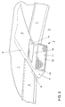
- Fig. 1 shows a mirror-image desk-shaped roof module 2 with the sky part 4, which is an integral part of the sky 1 on the one hand and on the other hand placed on the windshield 3.
- the sun visors 6 and 7 nestle against the edge 9 of the roof module with their edges 8, which are complementarily shaped to the edge 9 of the roof module, when they are folded against the roof 1.
- the edge 8 of the sun visor 6 is designed so that it slides along the side surface 5 of the housing leg 15 and thus the windshield 3 can screen almost without gap to the side wall 5 of the housing leg 15 when it is folded down.
- the sun visor 6 can pull into a latching groove 10, engage on the sky part 4 of the roof module 2.
- the mirror 11 is integrated in the housing leg 15 in such a way that it is enclosed by a padded edge 12 and is placed slightly away from the end face of the leg 15 in a recess 13 in the housing leg 15.
- the sky part 4 of the roof module 2 is supplemented by an illumination device 14.
- FIG. 2 shows a structure of a roof module 2 'in a similar manner to that shown in FIG. 1 the same components and its integration in the sky 1 of the car roof and the Arrangement between the sun visors 6 and 7.
- the edge 8 'of the Sun visor 6 close to the edge 9 'of the roof module, both in the illustrated Folding position towards the sky as well as in a folding position not shown Windshield 3 back.
- the leg 15 of the roof module 2 extends from the sky part 4 along the windshield 3, so that the depth of the leg 15 is made larger than in the example of Fig. 1.
- the headliner 4 ' is here as an elongated molded part in the Heaven 1 used or manufactured together with this as a one-piece component been.
- the mirror 11 here is provided with a narrow frame 12 ', what gives the entire roof module an appearance adapted to the sky 1, which means that Optical illusion is caused that the roof module 2 'is an integral part of Roof 1 or in combination with the sun visors 6 and 7.
Landscapes
- Engineering & Computer Science (AREA)
- Mechanical Engineering (AREA)
- Multimedia (AREA)
- Body Structure For Vehicles (AREA)
- Rear-View Mirror Devices That Are Mounted On The Exterior Of The Vehicle (AREA)
- Vehicle Step Arrangements And Article Storage (AREA)
Abstract
Description
Damit wird erreicht, daß kaum Lücken zwischen den hochgeklappten bzw. heruntergeklappten Sonnenblenden und dem so gestalteten Dachmodul entstehen und somit eine Sonneneinstrahlung einerseits maximal abgeschattet wird und andererseits im hochgeklappten Zustand die Sonnenblenden sich in etwa an die Kontur des Dachmoduls anschmiegen.
Fig. 1 zeigt ein spiegelbildlich pultförmiges Dachmodul 2 mit dem Himmelteil 4, welches einerseits integraler Bestandteil des Himmels 1 und andererseits auf die Windschutzscheibe 3 aufgesetzt ist. Links und rechts des Dachmoduls 2 schmiegen sich an die Kante 9 des Dachmoduls die Sonnenblenden 6 und 7 mit ihren zur Kante 9 des Dachmoduls komplementär geformten Kanten 8 an das Dachmodul an, wenn sie an den Himmel 1 geklappt sind. Es ist deutlich zu erkennen, daß die Kante 8 der Sonnenblende 6 so gestaltet ist, daß sie knapp an der Seitenfläche 5 des Gehäuseschenkels 15 entlanggleitet und somit die Windschutzscheibe 3 fast spaltlos zur Seitenwand 5 des Gehäuseschenkels 15 abblenden kann, wenn sie heruntergeklappt ist. In der dargestellten Stellung kann die Sonnenblende 6 in eine Rastnute 10 ziehen, am Himmelteil 4 des Dachmoduls 2 einrasten. In dem Gehäuseschenkel 15 ist der Spiegel 11 so integriert, daß er durch eine gepolsterte Kante 12 umschlossen wird und von der Stirnfläche des Schenkels 15 geringfügig weg in einer Vertiefung 13 des Gehäuseschenkels 15 plaziert ist. Selbst wenn der durch einen nicht dargestellten Elektromotor manipulierte Spiegel 11 in eine Kippstellung gerät, überragen die Kanten des Spiegels 11 die gepolsterte Kante 12 des Gehäuseschenkels gar nicht oder maximal um einen geringen Betrag. Ergänzt wird der Himmelteil 4 des Dachmoduls 2 durch eine Beleuchtungseinrichtung 14.
- 1
- Himmel
- 2, 2'
- Dachmodul
- 3
- Windschutzscheibe
- 4, 4'
- Himmelteil
- 5, 5'
- seitliche Außenkontur
- 6, 7
- Sonnenblenden
- 8, 8'
- Kanten
- 9, 9'
- seitliche Außenkontur
- 10
- Rastnute
- 11
- Rückspiegel
- 12, 12'
- Stirnfläche
- 13
- Vertiefung
- 14
- Beleuchtungseinrichtung
- 15
- Gehäuseschenkel
Claims (7)
- Dachmodul, ausgebildet als sichtbarer Teil eines Himmels eines Kraftfahrzeuges, mit einem sich zwischen einer Windschutzscheibe und einem inneren Rückspiegel erstreckenden Gehäuseschenkel,
dadurch gekennzeichnet, daßes als komplementäres Teil (2,2') in den als Formteil ausgebildeten Himmel (1) integrierbar ist, wobei der Gehäuseschenkel (15) zugleich ein den Rückspiegel (11) umrahmendes Gehäuse bildet. - Dachmodul nach Anspruch 1,
dadurch gekennzeichnet, daßdie Projektion seiner seitlichen Außenkontur (9, 9'; 5, 5') komplementär zur Projektion der Kanten (8, 8') von seitlich zu ihm angeordneten Sonnenblenden (6, 7) ausgebildet ist. - Dachmodul nach Anspruch 1 oder 2,
dadurch gekennzeichnet, daßder Gehäuseschenkel (15) den Raum zwischen Windschutzscheibe (3) und Spiegel (11) ausfüllt. - Dachmodul nach einem der Ansprüche 1 bis 3,
dadurch gekennzeichnet, daßvorzugsweise sein Gehäuseschenkel (15) der Aufnahme von Sensoren für Regen, Abblendung und ähnliches dient. - Dachmodul nach einem der Ansprüche 1 bis 4,
dadurch gekennzeichnet, daßder Rückspiegel (11) elektrisch verstellbar ausgebildet ist. - Dachmodul nach einem der Ansprüche 1 bis 5,
dadurch gekennzeichnet, daßes zum Fahrzeuginneren hin eine Stirnfläche (12, 12') bildet, in die der Rückspiegel (11) derart integriert ist, daß er in Kippstellung diese maximal knapp überragt. - Dachmodul nach einem der Ansprüche 1 bis 6,
dadurch gekennzeichnet, daßeine Beleuchtungseinrichtung (14) in seinem Himmelteil (4, 4') integriert ist.
Applications Claiming Priority (2)
| Application Number | Priority Date | Filing Date | Title |
|---|---|---|---|
| DE19931023 | 1999-07-06 | ||
| DE19931023A DE19931023A1 (de) | 1999-07-06 | 1999-07-06 | Dachmodul mit Rückspiegel |
Publications (2)
| Publication Number | Publication Date |
|---|---|
| EP1067019A1 true EP1067019A1 (de) | 2001-01-10 |
| EP1067019B1 EP1067019B1 (de) | 2004-09-29 |
Family
ID=7913739
Family Applications (1)
| Application Number | Title | Priority Date | Filing Date |
|---|---|---|---|
| EP00112996A Expired - Lifetime EP1067019B1 (de) | 1999-07-06 | 2000-06-21 | Dachmodul mit Rückspiegel |
Country Status (3)
| Country | Link |
|---|---|
| EP (1) | EP1067019B1 (de) |
| AT (1) | ATE277791T1 (de) |
| DE (2) | DE19931023A1 (de) |
Cited By (5)
| Publication number | Priority date | Publication date | Assignee | Title |
|---|---|---|---|---|
| WO2003093061A1 (de) * | 2002-04-29 | 2003-11-13 | Magna Donnelly Gmbh & Co. Kg | Abdeckmodul |
| WO2005032889A1 (de) * | 2003-09-02 | 2005-04-14 | Valeo Schalter Und Sensoren Gmbh | Dachmodul für ein kraftfahrzeug |
| EP1452397B1 (de) * | 2003-02-28 | 2005-12-28 | The Boeing Company | Integrale, geformte Innenverkleidung |
| FR3089905A1 (fr) | 2018-12-17 | 2020-06-19 | Renault S.A.S. | Agencement interieur de retro vision en partie haute de pare-brise et retroviseur interieur a deux positions |
| WO2021083709A1 (de) * | 2019-10-30 | 2021-05-06 | Man Truck & Bus Se | Kraftfahrzeug mit sonnenblenden |
Families Citing this family (1)
| Publication number | Priority date | Publication date | Assignee | Title |
|---|---|---|---|---|
| DE102012018192A1 (de) * | 2012-09-14 | 2014-05-15 | GM Global Technology Operations LLC (n. d. Gesetzen des Staates Delaware) | Fahrzeugkonsole mit einer Beleuchtungseinrichtung und Kraftfahrzeug mit einer solchen Fahrzeugkonsole |
Citations (7)
| Publication number | Priority date | Publication date | Assignee | Title |
|---|---|---|---|---|
| JPS6250223A (ja) * | 1985-07-16 | 1987-03-04 | Fuji Heavy Ind Ltd | サンル−フ自動車のル−フ構造 |
| EP0285589A2 (de) * | 1987-04-03 | 1988-10-05 | Autopart Sweden Ab | Sonnenblendenanordnung für Kraftfahrzeuge |
| US5331525A (en) * | 1993-01-14 | 1994-07-19 | United Technologies Automotive, Inc. | Low profile sun visor system with remote lighting |
| DE4329983A1 (de) | 1993-09-04 | 1995-03-09 | Bosch Gmbh Robert | Dachmodul für ein Kraftfahrzeug |
| DE19530617A1 (de) * | 1995-08-21 | 1997-02-27 | Fuba Automotive Gmbh | Aufnahme für Bauelemente im Bereich der Frontscheibe eines Kraftfahrzeugs |
| DE19653431A1 (de) | 1995-12-21 | 1997-07-03 | Yazaki Corp | Dachmodul und Baustruktur für den Zusammenbau desselben |
| JPH10324196A (ja) * | 1997-05-23 | 1998-12-08 | Kojima Press Co Ltd | 車両用アンテナ装置 |
Family Cites Families (2)
| Publication number | Priority date | Publication date | Assignee | Title |
|---|---|---|---|---|
| DE19647203C2 (de) * | 1996-11-15 | 1998-09-10 | Kostal Leopold Gmbh & Co Kg | Gehäuse für Dachmodul |
| DE19753879C1 (de) * | 1997-12-05 | 1998-12-03 | Kostal Leopold Gmbh & Co Kg | Dachmodul |
-
1999
- 1999-07-06 DE DE19931023A patent/DE19931023A1/de not_active Withdrawn
-
2000
- 2000-06-21 DE DE50007962T patent/DE50007962D1/de not_active Expired - Lifetime
- 2000-06-21 AT AT00112996T patent/ATE277791T1/de not_active IP Right Cessation
- 2000-06-21 EP EP00112996A patent/EP1067019B1/de not_active Expired - Lifetime
Patent Citations (7)
| Publication number | Priority date | Publication date | Assignee | Title |
|---|---|---|---|---|
| JPS6250223A (ja) * | 1985-07-16 | 1987-03-04 | Fuji Heavy Ind Ltd | サンル−フ自動車のル−フ構造 |
| EP0285589A2 (de) * | 1987-04-03 | 1988-10-05 | Autopart Sweden Ab | Sonnenblendenanordnung für Kraftfahrzeuge |
| US5331525A (en) * | 1993-01-14 | 1994-07-19 | United Technologies Automotive, Inc. | Low profile sun visor system with remote lighting |
| DE4329983A1 (de) | 1993-09-04 | 1995-03-09 | Bosch Gmbh Robert | Dachmodul für ein Kraftfahrzeug |
| DE19530617A1 (de) * | 1995-08-21 | 1997-02-27 | Fuba Automotive Gmbh | Aufnahme für Bauelemente im Bereich der Frontscheibe eines Kraftfahrzeugs |
| DE19653431A1 (de) | 1995-12-21 | 1997-07-03 | Yazaki Corp | Dachmodul und Baustruktur für den Zusammenbau desselben |
| JPH10324196A (ja) * | 1997-05-23 | 1998-12-08 | Kojima Press Co Ltd | 車両用アンテナ装置 |
Non-Patent Citations (2)
| Title |
|---|
| PATENT ABSTRACTS OF JAPAN vol. 011, no. 238 (M - 613) 5 August 1987 (1987-08-05) * |
| PATENT ABSTRACTS OF JAPAN vol. 1999, no. 03 31 March 1999 (1999-03-31) * |
Cited By (6)
| Publication number | Priority date | Publication date | Assignee | Title |
|---|---|---|---|---|
| WO2003093061A1 (de) * | 2002-04-29 | 2003-11-13 | Magna Donnelly Gmbh & Co. Kg | Abdeckmodul |
| US7306276B2 (en) | 2002-04-29 | 2007-12-11 | Magna Donnelly Gmbh & Co. Kg | Cover module |
| EP1452397B1 (de) * | 2003-02-28 | 2005-12-28 | The Boeing Company | Integrale, geformte Innenverkleidung |
| WO2005032889A1 (de) * | 2003-09-02 | 2005-04-14 | Valeo Schalter Und Sensoren Gmbh | Dachmodul für ein kraftfahrzeug |
| FR3089905A1 (fr) | 2018-12-17 | 2020-06-19 | Renault S.A.S. | Agencement interieur de retro vision en partie haute de pare-brise et retroviseur interieur a deux positions |
| WO2021083709A1 (de) * | 2019-10-30 | 2021-05-06 | Man Truck & Bus Se | Kraftfahrzeug mit sonnenblenden |
Also Published As
| Publication number | Publication date |
|---|---|
| DE50007962D1 (de) | 2004-11-04 |
| ATE277791T1 (de) | 2004-10-15 |
| DE19931023A1 (de) | 2001-01-11 |
| EP1067019B1 (de) | 2004-09-29 |
Similar Documents
| Publication | Publication Date | Title |
|---|---|---|
| EP0096154B1 (de) | Sonnenblende, insbesondere für Fahrzeuge | |
| EP0481196B1 (de) | Frontscheibe eines Kraftwagens | |
| DE4228782A1 (de) | Sonnenblenden- und kosmetikspiegel-system fuer ein kraftfahrzeug | |
| EP1400384A2 (de) | Sonnenschutz für ein Kraftfahrzeug | |
| DE102013006846A1 (de) | Blendschutzvorrichtung für ein Fahrzeug | |
| DE68910710T2 (de) | Blendschutzscheibe. | |
| DE2631712A1 (de) | Sonnenblendenanordnung, z.b. fuer fahrzeuge | |
| EP1067019B1 (de) | Dachmodul mit Rückspiegel | |
| DE102008063153A1 (de) | Sonnenblende | |
| DE102016204490A1 (de) | Vorrichtung für ein Fahrzeug, Fahrzeug | |
| DE4413905C1 (de) | Steuerung für eine Blendschutzscheibe an der Windschutzscheibe eines Kraftwagens | |
| DE3151315A1 (de) | Blendschutzvorrichtung fuer kraftfahrzeuge | |
| DE3035618C2 (de) | ||
| DE102024106257B3 (de) | Fahrzeugsblendensysteme mit multidirektionaler beschattung | |
| DE19539631A1 (de) | Dacheinbaubaugruppe für Fahrzeuge | |
| DE20003179U1 (de) | Sonnenblende für Kraftfahrzeuge | |
| DE9411342U1 (de) | Blendschutzvorrichtung mit Sichtbereich | |
| DE102005020234B4 (de) | Innenrückspiegel mit integrierten Sonnenschutzblenden | |
| DE9108186U1 (de) | Blendschutz | |
| DE1555949A1 (de) | Verschiebgbbare Kraftwagen-Sonnenblende | |
| DE9113706U1 (de) | Blendschutzvorrichtung gegen von außen ins Fahrzeuginnere eintretendes Blendlicht, vorzugsweise vom Außenspiegel kommend | |
| EP4703164A1 (de) | Zusatz-sonnenblende für kraftfahrzeuge | |
| EP0786364A1 (de) | Blendschutz für Kraftfahrzeuge | |
| DE19509425A1 (de) | Anordnung mit einem Fahrzeuginnenspiegel und einem Sonnenschutz | |
| AT1495U1 (de) | Blendschutz für kraftfahrzeuge |
Legal Events
| Date | Code | Title | Description |
|---|---|---|---|
| PUAI | Public reference made under article 153(3) epc to a published international application that has entered the european phase |
Free format text: ORIGINAL CODE: 0009012 |
|
| AK | Designated contracting states |
Kind code of ref document: A1 Designated state(s): AT BE CH CY DE DK ES FI FR GB GR IE IT LI LU MC NL PT SE |
|
| AX | Request for extension of the european patent |
Free format text: AL;LT;LV;MK;RO;SI |
|
| 17P | Request for examination filed |
Effective date: 20010710 |
|
| AKX | Designation fees paid |
Free format text: AT BE CH CY DE DK ES FI FR GB GR IE IT LI LU MC NL PT SE |
|
| 17Q | First examination report despatched |
Effective date: 20030722 |
|
| GRAP | Despatch of communication of intention to grant a patent |
Free format text: ORIGINAL CODE: EPIDOSNIGR1 |
|
| GRAS | Grant fee paid |
Free format text: ORIGINAL CODE: EPIDOSNIGR3 |
|
| GRAA | (expected) grant |
Free format text: ORIGINAL CODE: 0009210 |
|
| AK | Designated contracting states |
Kind code of ref document: B1 Designated state(s): AT BE CH CY DE DK ES FI FR GB GR IE IT LI LU MC NL PT SE |
|
| PG25 | Lapsed in a contracting state [announced via postgrant information from national office to epo] |
Ref country code: IT Free format text: LAPSE BECAUSE OF FAILURE TO SUBMIT A TRANSLATION OF THE DESCRIPTION OR TO PAY THE FEE WITHIN THE PRESCRIBED TIME-LIMIT;WARNING: LAPSES OF ITALIAN PATENTS WITH EFFECTIVE DATE BEFORE 2007 MAY HAVE OCCURRED AT ANY TIME BEFORE 2007. THE CORRECT EFFECTIVE DATE MAY BE DIFFERENT FROM THE ONE RECORDED. Effective date: 20040929 Ref country code: IE Free format text: LAPSE BECAUSE OF FAILURE TO SUBMIT A TRANSLATION OF THE DESCRIPTION OR TO PAY THE FEE WITHIN THE PRESCRIBED TIME-LIMIT Effective date: 20040929 Ref country code: FI Free format text: LAPSE BECAUSE OF FAILURE TO SUBMIT A TRANSLATION OF THE DESCRIPTION OR TO PAY THE FEE WITHIN THE PRESCRIBED TIME-LIMIT Effective date: 20040929 Ref country code: FR Free format text: LAPSE BECAUSE OF FAILURE TO SUBMIT A TRANSLATION OF THE DESCRIPTION OR TO PAY THE FEE WITHIN THE PRESCRIBED TIME-LIMIT Effective date: 20040929 Ref country code: GB Free format text: LAPSE BECAUSE OF FAILURE TO SUBMIT A TRANSLATION OF THE DESCRIPTION OR TO PAY THE FEE WITHIN THE PRESCRIBED TIME-LIMIT Effective date: 20040929 Ref country code: NL Free format text: LAPSE BECAUSE OF FAILURE TO SUBMIT A TRANSLATION OF THE DESCRIPTION OR TO PAY THE FEE WITHIN THE PRESCRIBED TIME-LIMIT Effective date: 20040929 |
|
| REG | Reference to a national code |
Ref country code: GB Ref legal event code: FG4D Free format text: NOT ENGLISH |
|
| REG | Reference to a national code |
Ref country code: CH Ref legal event code: EP |
|
| REG | Reference to a national code |
Ref country code: IE Ref legal event code: FG4D Free format text: GERMAN |
|
| REF | Corresponds to: |
Ref document number: 50007962 Country of ref document: DE Date of ref document: 20041104 Kind code of ref document: P |
|
| PG25 | Lapsed in a contracting state [announced via postgrant information from national office to epo] |
Ref country code: GR Free format text: LAPSE BECAUSE OF FAILURE TO SUBMIT A TRANSLATION OF THE DESCRIPTION OR TO PAY THE FEE WITHIN THE PRESCRIBED TIME-LIMIT Effective date: 20041229 Ref country code: SE Free format text: LAPSE BECAUSE OF FAILURE TO SUBMIT A TRANSLATION OF THE DESCRIPTION OR TO PAY THE FEE WITHIN THE PRESCRIBED TIME-LIMIT Effective date: 20041229 Ref country code: DK Free format text: LAPSE BECAUSE OF FAILURE TO SUBMIT A TRANSLATION OF THE DESCRIPTION OR TO PAY THE FEE WITHIN THE PRESCRIBED TIME-LIMIT Effective date: 20041229 |
|
| PG25 | Lapsed in a contracting state [announced via postgrant information from national office to epo] |
Ref country code: ES Free format text: LAPSE BECAUSE OF FAILURE TO SUBMIT A TRANSLATION OF THE DESCRIPTION OR TO PAY THE FEE WITHIN THE PRESCRIBED TIME-LIMIT Effective date: 20050109 |
|
| NLV1 | Nl: lapsed or annulled due to failure to fulfill the requirements of art. 29p and 29m of the patents act | ||
| REG | Reference to a national code |
Ref country code: IE Ref legal event code: FD4D |
|
| GBV | Gb: ep patent (uk) treated as always having been void in accordance with gb section 77(7)/1977 [no translation filed] |
Effective date: 20040929 |
|
| PG25 | Lapsed in a contracting state [announced via postgrant information from national office to epo] |
Ref country code: LU Free format text: LAPSE BECAUSE OF NON-PAYMENT OF DUE FEES Effective date: 20050621 Ref country code: CY Free format text: LAPSE BECAUSE OF FAILURE TO SUBMIT A TRANSLATION OF THE DESCRIPTION OR TO PAY THE FEE WITHIN THE PRESCRIBED TIME-LIMIT Effective date: 20050621 Ref country code: AT Free format text: LAPSE BECAUSE OF NON-PAYMENT OF DUE FEES Effective date: 20050621 |
|
| PG25 | Lapsed in a contracting state [announced via postgrant information from national office to epo] |
Ref country code: CH Free format text: LAPSE BECAUSE OF NON-PAYMENT OF DUE FEES Effective date: 20050630 Ref country code: MC Free format text: LAPSE BECAUSE OF NON-PAYMENT OF DUE FEES Effective date: 20050630 Ref country code: BE Free format text: LAPSE BECAUSE OF NON-PAYMENT OF DUE FEES Effective date: 20050630 Ref country code: LI Free format text: LAPSE BECAUSE OF NON-PAYMENT OF DUE FEES Effective date: 20050630 |
|
| PLBE | No opposition filed within time limit |
Free format text: ORIGINAL CODE: 0009261 |
|
| STAA | Information on the status of an ep patent application or granted ep patent |
Free format text: STATUS: NO OPPOSITION FILED WITHIN TIME LIMIT |
|
| 26N | No opposition filed |
Effective date: 20050630 |
|
| EN | Fr: translation not filed | ||
| REG | Reference to a national code |
Ref country code: CH Ref legal event code: PL |
|
| BERE | Be: lapsed |
Owner name: *VOLKSWAGEN A.G. Effective date: 20050630 |
|
| PG25 | Lapsed in a contracting state [announced via postgrant information from national office to epo] |
Ref country code: PT Free format text: LAPSE BECAUSE OF NON-PAYMENT OF DUE FEES Effective date: 20050228 |
|
| PGFP | Annual fee paid to national office [announced via postgrant information from national office to epo] |
Ref country code: DE Payment date: 20140630 Year of fee payment: 15 |
|
| REG | Reference to a national code |
Ref country code: DE Ref legal event code: R119 Ref document number: 50007962 Country of ref document: DE |
|
| PG25 | Lapsed in a contracting state [announced via postgrant information from national office to epo] |
Ref country code: DE Free format text: LAPSE BECAUSE OF NON-PAYMENT OF DUE FEES Effective date: 20160101 |